1
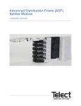
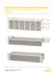
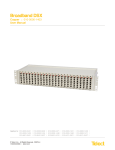
Dual Monitor DM-84
User Manual
Dual Monitor DM-84
User Manual 117883 A1.1
Copyright 2010, Telect, Inc., All Rights Reserved
Telect and Connecting the Future are registered trademarks of Telect, Inc.
1730 N Madson St., Liberty Lake, Washington
Telect assumes no liability from the application or use of these products. Neither does Telect convey any
license under its patent rights nor the patent rights of others. This document and the products described
herein are subject to change without notice.
About Telect
Telect offers complete solutions for physical layer connectivity, power, equipment housing and other
network infrastructure equipment. From outside plant and central office to inside the home, Telect draws
on more than 25 years of experience to deliver leading edge product and service solutions. Telect is
committed to providing superior customer service and is capable of meeting the dynamic demands of
customer and industry requirements. This commitment to customer and industry excellence has positioned
Telect as a leading connectivity and power solution provider for the global communications industry.
Technical Support
E-mail: [email protected]
Phone: 888-821-4856 or 509-921-6161
Telect, Inc. • USA +1.509.926.6000 • Mexico +52.33.3836.37.52
www.telect.com • © 2010 Telect, Inc., All Rights Reserved, 117883 A1.1
Page ii
Dual Monitor DM-84
User Manual
Table of Contents
Chapter 1: Descriptions ............................................................................................................ 1
1.1 Dual Monitor 84-Termination FXC ................................................................................... 1
1.1.1 Features .................................................................................................................. 1
1.2 Specifications ................................................................................................................... 2
1.2.1 Electrical .................................................................................................................. 3
1.2.2 Mechanical .............................................................................................................. 3
1.2.3 Environmental ......................................................................................................... 3
1.3 System-Level Applications................................................................................................ 4
Chapter 2: Installation ............................................................................................................... 5
2.1 Installation Considerations ............................................................................................... 5
2.1.1 Location and Space ................................................................................................ 5
2.1.2 Tools and Equipment .............................................................................................. 5
2.2 Inspection......................................................................................................................... 5
2.3 Installation Procedure ...................................................................................................... 6
Chapter 3: User Functions ........................................................................................................ 7
3.1 Cross-connecting Circuits ................................................................................................ 7
3.2 Patching ........................................................................................................................... 8
3.2.1 Two Single Patch Cords .......................................................................................... 8
3.2.2 Dual Patch Cord ...................................................................................................... 9
3.3 Monitor Functions .......................................................................................................... 10
3.4 Patch and Roll ................................................................................................................ 10
Chapter 4: Service ................................................................................................................... 13
4.1 Changing Jack Modules ................................................................................................. 13
4.1.1 Removing a Jack Module ...................................................................................... 13
4.1.2 Inserting a Jack Module ........................................................................................ 14
4.2 Changing LEDs .............................................................................................................. 14
4.3 Cross-Connections ........................................................................................................ 15
4.4 In-Warranty Service ....................................................................................................... 15
4.5 Out-Of-Warranty Service ............................................................................................... 15
4.6 Repacking For Shipment ............................................................................................... 15
Telect, Inc. • USA +1.509.926.6000 • Mexico +52.33.3836.37.52
www.telect.com • © 2010 Telect, Inc., All Rights Reserved, 117883 A1.1
Page iii
List of Figures
Figure 1 - Chassis - front view ..................................................................................................... 1
Figure 2 - Rear View .................................................................................................................... 1
Figure 3 - Physical dimensions .................................................................................................... 2
Figure 4 - Jack Schematic ........................................................................................................... 2
Figure 5 - Jack - PN 400220 (odd - shown), 400221 (even) ....................................................... 3
Figure 6 - 7’ racks, fully configured — typical EIA rack installation .............................................. 4
Figure 7 - Installing the Jumper Rings ......................................................................................... 6
Figure 8 - Cross-connecting Circuits ............................................................................................ 7
Figure 9 - Wire-wrap Cross Connect ........................................................................................... 8
Figure 10 - Using Two Single Patch Cords .................................................................................. 9
Figure 11 - Using a Dual Patch Cord ........................................................................................... 9
Figure 12 - Installing the patch cords ......................................................................................... 10
Figure 13 - Establishing Service ................................................................................................ 11
Figure 14 - Pulling the retainer pins ........................................................................................... 13
Figure 15 - Pulling the Jack Module ........................................................................................... 13
Figure 16 - Inserting a Jack Module ........................................................................................... 14
Figure 17 - Inserting the LED ..................................................................................................... 14
Telect, Inc. • USA +1.509.926.6000 • Mexico +52.33.3836.37.52
www.telect.com • © 2010 Telect, Inc., All Rights Reserved, 117883 A1.1
Page iv
Chapter 1: Descriptions
1.1 Dual Monitor
84-Termination FXC
Telect’s Dual Monitor 84-circuit Front Crossconnect panel (PN 010-DM84-7001) is
designed to cross-connect, patch, monitor
and allow test access to these circuits
carrying these digital signals:
•
DS1 (1.544 Mb/s at 100Ω impedance)
•
DS1C (3.152 Mb/s at 100Ω impedance)
Figure 1 - Chassis - front view
1.1.1 Features
•
Bi-directional monitoring from the front of
the panel.
•
The 7” (17.78 cm)-high panels attach to a
23” (58.4 cm) rack. Extended mount can
be adjusted for 2”, 3”, and 4” (5, 7.6, and
10.2 cm) offset.
•
The 7” panels work well with either EIA
or WECO.
•
The fully-loaded panel weighs 26.5 lbs. (12 kg.)
•
Offset Bantam jack spacing accommodates standard Bantam cords in adjacent jacks permitting the use of industry standard patch cords.
•
Insert-molded Plasti-Frame jacks meet all Bellcore standards for durability and reliability.
•
Individual jacks detach from the chassis allowing the removal of a single jack without disrupting service at any other termination. Jack removal requires no I/O cabling or
cross-connect changes.
•
Each circuit has an LED for cross-connect verification.
•
All pins are 0.45” square (.11 cm), suitable for 20-26AWG conductors.
Figure 2 - Rear View
Telect, Inc. • USA +1.509.926.6000 • Mexico +52.33.3836.37.52
www.telect.com • © 2010 Telect, Inc., All Rights Reserved, 117883 A1.1
Page 1-1
1.2 Specifications
6.94 in.
(17.63 cm
Figure 3 - Physical dimensions
BATT
SGND
RTN
C. GND
TIP
RING
120Ω
MON
430 Ω
430 Ω
430 Ω
430 Ω
OUT
OUT
IN
TIP
MON
IN
RING
All resistors are 1/16 watt
OUT
IN
TL
OXT
OXR
IXT
IXR
FRONT CROSS CONNECT
Figure 4 - Jack Schematic
Telect, Inc. • USA +1.509.926.6000 • Mexico +52.33.3836.37.52
www.telect.com • © 2010 Telect, Inc., All Rights Reserved, 117883 A1.1
Page 1-2
Figure 5 - Jack - PN 400220 (odd - shown), 400221 (even)
The jack has been designed to meet the following criteria:
1.2.1 Electrical
Insertion Loss: <−0.5 dB at 772 kHz and 1.024 MHz
Adjacent Channel (1 to 2) Crosstalk: < -60 dB at 1.024 Mhz
Crosstalk— DS1, DS1C: < −70 dB
Return Loss: ≥ 26 dB at 772 kHz and 1.024 MHz
Monitor level, jack in/jack out: -20 dB (-1 dB +/-0.5 dB)
Contact Resistance: ≤ 0.01Ω
1.2.2 Mechanical
Insertion Force: 4.17 lb (1.9 kg) average
Withdrawal Force: 5.21 lb (2.4 kg) average
Life: Minimum 20,000 insertion/withdrawal cycles
Vibration: Per MIL-STD-202F, Method 201A
1.2.3 Environmental
Humidity: To 95% (operating and non-operating)
Moisture Resistance: Per MIL-STD-202F, Method 106E
Salt Spray: Per MIL-STD-202F, Method 101D
Telect, Inc. • USA +1.509.926.6000 • Mexico +52.33.3836.37.52
www.telect.com • © 2010 Telect, Inc., All Rights Reserved, 117883 A1.1
Page 1-3
Temperature: –40 to 149°F (–40 to 65°C) operating
–67 to 185°F (–55 to 85°C) non-operating
Thermal Shock: Per MIL-STD-202, Method 107D
1.3 System-Level Applications
Dual Monitor DM-84
Dual Monitor DM-84
Dual Monitor DM-84
Dual Monitor DM-84
Dual Monitor DM-84
Dual Monitor DM-84
Dual Monitor DM-84
Dual Monitor DM-84
Dual Monitor DM-84
Figure 6 - 7’ racks, fully configured — typical EIA rack installation
Telect, Inc. • USA +1.509.926.6000 • Mexico +52.33.3836.37.52
www.telect.com • © 2010 Telect, Inc., All Rights Reserved, 117883 A1.1
Page 1-4
Chapter 2: Installation
2.1 Installation Considerations
These procedures may be modified to agree with site practices or procedures.
2.1.1 Location and Space
Each Dual Monitor DM-84 chassis requires 7” (17.8 cm) of vertical space in a 23" (58.4 cm) rack.
2.1.2 Tools and Equipment
No special tools or equipment are needed.
2.2 Inspection
Compare the contents of the Dual Monitor DM-84 shipping container with the packing list. Call
Telect if you are missing anything.
Telect is not liable for shipping damage.
If the shipping container is damaged, keep it for the carrier’s inspection. Notify the carrier and call
Telect’s Customer Service Department: 1-800-551-4567 or 1-509-926-6000.
Keep the container until you have checked equipment operation. If you experience any kind of
problem, call Telect’s Customer Service Department. Use the original, undamaged container if
you are instructed to return the DM-84 to Telect.
Telect, Inc. • USA +1.509.926.6000 • Mexico +52.33.3836.37.52
www.telect.com • © 2010 Telect, Inc., All Rights Reserved, 117883 A1.1
Page 2-5
2.3 Installation Procedure
Procedure steps:
1. Place the jumper wire rings over the
studs on the mounting brackets and
partially tighten the top screw and
washer as shown (A), using the washers and screws provided.
2. Repeat step 1 on the other end of
the panel.
3. Align cable management device and install the three remaining screws on
each side.
4. Tighten all mounting screws to 35 inlbs. (4.29 N•m).
5. Connect the shield ground according to
your company’s procedure.
6. Connect power at the rear of the panel
to the wire wrap pins marked BATT and
RTN. Do not turn on.
A
7. Connect the Input/Output cabling from
the digital equipment to Input/Output
pins on the panel backplane.
8. Connect the “DIGITAL XMIT” connector
on the equipment to the OUT pins on
the DM-84.
PN 117397
9. Connect the “DIGITAL REC” on the
equipment to the IN pins on the DM-84.
10. See “User Functions” on page 7 for instructions on creating cross-connects.
Figure 7 - Installing the Jumper Rings
This procedure is complete.
Telect, Inc. • USA +1.509.926.6000 • Mexico +52.33.3836.37.52
www.telect.com • © 2010 Telect, Inc., All Rights Reserved, 117883 A1.1
Page 2-6
Chapter 3: User Functions
3.1 Cross-connecting Circuits
Procedure steps:
1. Make cross-connects at the wire-wrap pins on the front of the DSX panel, using companyapproved wire-wrap techniques:
a. Use 5-conductor, 24AWG jumpers.
b. Attach the green jumper wire from the tracer lamp (TL) pin of the NE-1 jack to the TL pin
of the NE-2 jack.
c. Connect the OUT pins of NE-1 to the IN pins of NE-2 using the Wht-blue jumper for tip-totip and blue-white jumper for ting-to-ring connections.
d. Connect the IN pins of NE-1 to the OUT pins of NE-2 using the Wht-orange jumper for tipto-tip and orange-white jumpers for ring-to-ring.
NE-1
OUT
IN
Green
TL
T
R
T
R
Wht- Blue
Blue-white
Wht- Orange
ite
Orange-wh
TL NE-2
T
R OUT
T
IN
R
Figure 8 - Cross-connecting Circuits
e. Record the cross-connect circuit identification on the circuit designation strip on the front
of the Dual Monitor E-84 panel.
f.
Disconnect and discard any jumper wires not in use.
g. Route the jumper wires that are connected to jacks on the left half of the panel into the left
vertical wire rings.
h. Route the jumper wires that are connected to jacks on the right half into the right vertical
wire rings.
2. Apply power to the panel.
Telect, Inc. • USA +1.509.926.6000 • Mexico +52.33.3836.37.52
www.telect.com • © 2010 Telect, Inc., All Rights Reserved, 117883 A1.1
Page 3-7
3. Test the cross-connect by inserting a plug into MON jack of the first jack in the circuit. The
tracer lamps of both jacks in the circuit should flash for about 30 seconds, then light steadily.
NE-1
JACK
OUT
IN
NE-2
JACK
TL
T
R
T
R
TL
T
R OUT
T
IN
R
Figure 9 - Wire-wrap Cross Connect
This procedure is complete.
3.2 Patching
You can make temporary connections of circuits to repair, test, or monitor incoming and outgoing
lines, using either dual patch cords or two single patch cords.
3.2.1 Two Single Patch Cords
Procedure steps:
1. Insert a single patch cord into the IN jack of the NE-1 jack.
2. Insert the other end into the OUT jack of the NE-2 jack.
3. Insert another single patch cord into OUT jack of the NE-1 jack.
Telect, Inc. • USA +1.509.926.6000 • Mexico +52.33.3836.37.52
www.telect.com • © 2010 Telect, Inc., All Rights Reserved, 117883 A1.1
Page 3-8
4. Insert the other end of the patch cord into the IN jack of the NE-2 jack.
NE-2
NE-1
Figure 10 - Using Two Single Patch Cords
This procedure is complete.
3.2.2 Dual Patch Cord
Procedure steps:
1. Insert a dual patch cord into the IN and OUT ports of the NE-1 jack.
2. Twist the plug on the other end of the cord so that it is reversed (i.e., turned upside down from
the first selected pair). Insert this end into the In and Out ports of the NE-2 jack.
NE-2
NE-1
Figure 11 - Using a Dual Patch Cord
This procedure is complete.
Telect, Inc. • USA +1.509.926.6000 • Mexico +52.33.3836.37.52
www.telect.com • © 2010 Telect, Inc., All Rights Reserved, 117883 A1.1
Page 3-9
3.3 Monitor Functions
Insert a Bantam monitor jack from test equipment into the top Monitor jack to monitor the Out
signal for a circuit. Insert the test jack into the bottom Monitor jack to monitor the In signal.
These monitor procedures are non-intrusive.
3.4 Patch and Roll
Patching and rolling, as illustrated in the figures below, allows a circuit to be moved from an
existing facility (A) to a new or spare facility (C), including new permanent cross-connects.
Procedure steps:
1. Temporarily transfer the existing circuit from B to C by installing patch cords between the two
jacks as shown. Installing the patch cords in this way disconnects the A facility from the B and
at the same time establishes temporary continuity between B and C (new or spare facility).
FACILITY
A
FACILITY
B
OUT
IN
TL
T
R
T
R
TL
T
R OUT
T
IN
R
FACILITY
C
OUT
IN
TL
T
R
T
R
Figure 12 - Installing the patch cords
2. Remove the cross connects between the A and B facilities.
3. Place cross-connects between B and C.
Telect, Inc. • USA +1.509.926.6000 • Mexico +52.33.3836.37.52
www.telect.com • © 2010 Telect, Inc., All Rights Reserved, 117883 A1.1
Page 3-10
4. Remove the patch cords between B and C. Service is now established through the new
cross-connect jumpers.
FACILITY
A
FACILITY
B
OUT
IN
TL
T
R
T
R
TL
T
R OUT
T
IN
R
FACILITY
C
OUT
IN
TL
T
R
T
R
Figure 13 - Establishing Service
This procedure is complete.
Telect, Inc. • USA +1.509.926.6000 • Mexico +52.33.3836.37.52
www.telect.com • © 2010 Telect, Inc., All Rights Reserved, 117883 A1.1
Page 3-11
This page intentionally left blank.
Telect, Inc. • USA +1.509.926.6000 • Mexico +52.33.3836.37.52
www.telect.com • © 2010 Telect, Inc., All Rights Reserved, 117883 A1.1
Page 3-12
Chapter 4: Service
4.1 Changing Jack Modules
You can remove a jack module from the panel without disturbing the
cross-connect wiring. However, removing the jack module does
disconnect the service provided by that circuit.
Jack to be
removed
4.1.1 Removing a Jack Module
Procedure steps:
Retainer
pins
1. Pull the small retainer pins at the top and bottom of the jack module
straight out, as shown. You can use a small screwdriver to disengage the retainer pins.
Figure 14 - Pulling the retainer pins
2. Insert a dual plug (to use as a handle) into the jack
module. Move the plug up and down slowly while pulling the jack module out of the panel.
This procedure is complete.
Dual
plug
Figure 15 - Pulling the Jack Module
Telect, Inc. • USA +1.509.926.6000 • Mexico +52.33.3836.37.52
www.telect.com • © 2010 Telect, Inc., All Rights Reserved, 117883 A1.1
Page 4-13
4.1.2 Inserting a Jack Module
Vacant Jack Slot
Procedure steps:
1. Slide a new jack module into the vacant slot in the DM-84
panel, as shown below. Insert the module carefully
and straight.
2
If you cannot feel the leads entering the sockets, wiggle
the module gently to align them. Do not force the module;
push it carefully into the sockets. All module pins must
align with sockets inside the DM-84.
1
2. Push in the retainer pins to secure the module.
3. Test the new jack module using standard
office procedures.
Figure 16 - Inserting a Jack
Module
This procedure is complete.
4.2 Changing LEDs
Should an LED burn out, you can quickly replace it.
Procedure steps:
1. Pull the defective LED straight out with your fingers.
2. Align the replacement LED with the LED socket in the jack module. Notice that the socket is
keyed, and the LED only enters one way.
!
CAUTION
CAUTION! Take care not to bend the LED’s two metal leads.
3. Gently insert the LED into the socket. If you encounter
resistance, do not force the LED into position. Move the
LED until it slides easily into the jack module.
Flat surface of LED to
flat surface of socket
4. When the LED snaps into place, the installation
is complete.
5. To test the new LED, insert a plug into the “M” (monitor)
jack. The LED will flash for about 30 seconds, then
light steadily.
Leads
LED
This procedure is complete.
(Use the subsections below that make the most sense for
your equipment.)
Figure 17 - Inserting the LED
If problems occur after initial installation, check all cable connections and the installation
instructions in Chapter 2.
Telect, Inc. • USA +1.509.926.6000 • Mexico +52.33.3836.37.52
www.telect.com • © 2010 Telect, Inc., All Rights Reserved, 117883 A1.1
Page 4-14
4.3 Cross-Connections
See User Functions, Chapter 3.
4.4 In-Warranty Service
Contact your Telect equipment distributor, or call a Telect Customer Service Representative:
1-800-551-4567
1-509-926-6000
Telect will repair or replace defective products within the limits of the warranty. See “Repacking
for Shipment” in this section.
Call a Customer Service Representative for a Return Material Authorization (RMA) before
returning any equipment.
4.5 Out-Of-Warranty Service
The procedure for out-of-warranty service is the same as for in-warranty service, except that
Telect charges a processing fee, and you must submit a Purchase Order along with a Return
Material Authorization (RMA) before returning equipment. Call a Customer Service
Representative for help getting these forms.
The processing fee guarantees a repair estimate and is credited against actual material and
labor costs.
4.6 Repacking For Shipment
1. Tag the equipment showing owner’s name, address, and telephone number, together with a
detailed description of the problem.
2. Use the original shipping container if possible. If you do not have it, package the equipment in
a way to prevent shipping damage. Include the RMA inside the container.
3. Insure the package.
NOTE: Telect is not liable for shipping damage.
Telect, Inc. • USA +1.509.926.6000 • Mexico +52.33.3836.37.52
www.telect.com • © 2010 Telect, Inc., All Rights Reserved, 117883 A1.1
Page 4-15
This page intentionally left blank.
Telect, Inc. • USA +1.509.926.6000 • Mexico +52.33.3836.37.52
www.telect.com • © 2010 Telect, Inc., All Rights Reserved, 117883 A1.1
Page 4-16