1
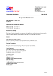
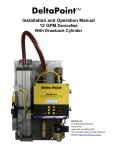
installation manual
Part Number: WP-5012-002-01
Whisper Tech reserves the right to revise or change product specifications at
any time. This publication describes the state of this product at the time of its
publication and may not reflect the product at all times in the future.
Patents granted and pending worldwide.
Whisper Tech, WhisperGen, Personal Power Station, and WhisperGen
Personal Power Station are registered trademarks of Whisper Tech Limited.
Title
Installation Manual - Models PPS16-12MD, PPS16-24MD
Part No.
WP 5012-002-01
Application
WhisperGen PPS16-12MD
Diesel fired
12 V DC output
Marine
WhisperGen PPS16-24MD
Diesel fired
24 V DC output
Marine
WhisperGen is designed and manufactured by
Whisper Tech
224 Armagh St
P O Box 13-705
Christchurch
New Zealand
www.whispergen.com
Copyright ©2005 Whisper Tech Limited
All Rights Reserved
Printed in New Zealand
Conditions of use
Read this manual completely before installing or
operating the WhisperGen.
The WhisperGen must be commissioned only by an
authorised WhisperGen representative. Whisper Tech
accepts no liability for personal injury or property
damage resulting from incorrect or unauthorised
installation, commissioning and servicing of the
WhisperGen. Unapproved installations may be
dangerous, result in poor performance and void any
WhisperGen warranty.
Along with any warnings, instructions and procedures
in this manual, the user should also observe any such
other common sense procedures generally applicable
to equipment of this type.
Failure by the user to comply with any warnings,
instructions, procedures, or any such other common
sense procedures may result in injury, equipment
damage, property damage or poor performance of the
WhisperGen. The major hazards involved with
operating the WhisperGen include explosion, fire,
carbon monoxide fumes and electrical shock. These
hazards can be avoided if the user adheres to the
procedures in this manual and exercises all due care.
Whisper Tech accepts no liability for direct, indirect,
incidental, special, or consequential damages resulting
from failure by the user, installer or service technician
to follow any warnings, instructions and procedures in
this manual, or any such other common sense
procedures generally applicable to equipment of this
type. The foregoing limitation extends to damages to
person or property caused by the WhisperGen, or
damages resulting from the inability to use the
WhisperGen, including loss of profits, loss of products,
loss of power supply, the cost of arranging an
alternative power supply and loss of time, whether
incurred by the user, its employees, the installer, a
service technician or any third party.
Whisper Tech reserves the right to change the
specifications of its products, or the information in this
manual, without necessarily notifying its users.
Variations in installation and operating conditions may
affect the WhisperGen’s performance. Whisper Tech
has no control over each installation's unique operating
environment. Hence, Whisper Tech makes no
representations or warranties concerning the
performance of the WhisperGen under the actual
operating conditions prevailing at the installation. All
operating parameters for each application should be
validated by a technical expert of the user’s choosing.
Whisper Tech has made every effort to explain all
installation, commissioning, operating, maintenance,
troubleshooting procedures, warnings and safety
precautions as clearly and completely as possible.
However, due to the range of operating environments it
is not possible to anticipate every issue that may arise.
Therefore, Whisper Tech is not able to guarantee that
this manual will address every issue that may arise.
This manual is intended to provide general guidance.
For specific guidance and technical support, contact
your authorised WhisperGen supplier.
Information in this manual shall not be deemed a
warranty, representation or guarantee. For warranty
provisions applicable to your WhisperGen, please refer
to the warranty provided by the supplier of your
WhisperGen.
Unless otherwise noted, reference to brand names,
product names or trademarks constitute the intellectual
property of the owner thereof. Subject to your right to
use the WhisperGen, Whisper Tech does not convey
any right, title or interest in its intellectual property,
including, without limitation, its patents, copyrights and
know-how.
No part of this manual may be reproduced or
transmitted in any form or by any means without the
express written permission of Whisper Tech.
Every effort has been made to ensure the accuracy of
this document, however it may contain technical
inaccuracies or typographical errors. Whisper Tech
assumes no responsibility for and disclaims all liability
of such inaccuracies, errors, or omissions in this
publication.
Use of the WhisperGen shall constitute your acceptance of the conditions above
Contents
Introduction and safety information................................................................................................................................ 1
Overview of the WhisperGen ................................................................................................................................... 1
Purpose of this manual ............................................................................................................................................ 1
Importance of correct installation ............................................................................................................................. 2
Symbols in this manual ............................................................................................................................................ 2
Emergency procedures ............................................................................................................................................ 2
Normal operation ..................................................................................................................................................... 3
Identification of main components............................................................................................................................ 3
Labels ...................................................................................................................................................................... 4
Compliance information ........................................................................................................................................... 5
Design and plan your installation.................................................................................................................................... 6
Introduction .............................................................................................................................................................. 6
Equipment supplied with the WhisperGen ............................................................................................................... 6
Installation kits (optional).......................................................................................................................................... 7
Select a site for the WhisperGen ............................................................................................................................. 8
Fuel system.............................................................................................................................................................. 9
Primary cooling system/boat heating system ......................................................................................................... 12
Secondary cooling system/seawater heat dump circuit ......................................................................................... 18
Exhaust & condensate drain .................................................................................................................................. 21
Fresh water flushing............................................................................................................................................... 23
Battery bank........................................................................................................................................................... 24
Install the WhisperGen ................................................................................................................................................... 25
Unpack the WhisperGen........................................................................................................................................ 25
Dispose of the packaging....................................................................................................................................... 25
Remove and re-fit the enclosure ............................................................................................................................ 25
Lift the WhisperGen ............................................................................................................................................... 26
Attach the exhaust heat exchanger........................................................................................................................ 26
Fix the WhisperGen into position ........................................................................................................................... 27
Connect fuel and plumbing fittings ......................................................................................................................... 28
Install the control panel .......................................................................................................................................... 29
Connect the electrical power and control wiring..................................................................................................... 30
Prepare for commissioning............................................................................................................................................ 33
To operate the control panel .................................................................................................................................. 33
Fill and bleed the primary coolant system.............................................................................................................. 34
Bleed the secondary cooling system...................................................................................................................... 36
Bleed the fuel system............................................................................................................................................. 37
Appendices...................................................................................................................................................................... 38
Transporting by land or air ..................................................................................................................................... 38
Technical specification........................................................................................................................................... 38
WhisperGen DC Marine Installation checklist ........................................................................................................ 41
Introduction and safety information
Overview of the WhisperGen
Introduction and safety information
Overview of the WhisperGen
The WhisperGen is a combined heat and power generating system
providing efficient, low maintenance generation of DC electric power. The
WhisperGen uses a four-cylinder double-acting external combustion
(Stirling cycle) engine.
Interconnected cylinders are pressurised with nitrogen gas and sealed. The
gas is heated at the top of the cylinders by a continuous combustion burner
and cooled at the bottom by coolant circulation. The resulting change in
pressure causes pistons inside the cylinders to move up and down. A
unique 'wobble yoke' mechanism ensures the correct phasing of the pistons
and converts their linear motion to rotary motion to drive a DC electrical
generator which can be used to charge a battery bank.
Key:
1.
2.
3.
4.
5.
6.
7.
8.
9.
9
WhisperGen
Battery bank
DC/AC inverter
Standard domestic appliances
Hot water for domestic use
Space heating
Excess heat removal
12 or 24 V equipment
Cool exhaust vent
6
5
4
8
1
3
2
7
The heat generated by the burner is removed by coolant circulating through
the engine cavities. The coolant used in the WhisperGen is circulated by
pump to heat hot water cylinders and to provide cabin heating.
A microcomputer controls all the WhisperGen functions and displays real
time operating conditions on an LCD control panel.
The WhisperGen DC output goes to a battery bank, which provides an
electrical buffer for the varying loads required. When the battery bank
charge is low the WhisperGen can be set to automatically start and bring
the charge back up to a preset level. Once the battery bank is charged the
WhisperGen can be set to either stop, or to continue operating to provide
heat energy.
DC electrical items can be run directly off the battery bank, and AC
appliances via a DC/AC inverter.
Purpose of this manual
This manual details the correct installation procedure for the:
WhisperGen PPS16-12MD diesel-fired generator with 12 V DC output
WhisperGen PPS16-24MD diesel-fired generator with 24 V DC output
and their associated systems, into recreational craft. The WhisperGen
must not be used in any other capacity.
Use the Installation checklist (on page 41) to guide you through installation.
A separate User Manual is provided for the general operation and
maintenance of the WhisperGen.
1
Introduction and safety information
Importance of correct installation
Importance of correct installation
The WhisperGen is technically advanced equipment that must be installed
correctly for reliable operation. It is recommended that installation be
undertaken by a suitably qualified person.
This manual outlines the correct way to install the WhisperGen.
After the WhisperGen is installed, an authorised WhisperGen
representative must do the final system checks, a first start, and
commissioning.
Failure to use an authorised WhisperGen representative for commissioning
may result in the warranty being void.
Please keep this manual in a secure place near the WhisperGen.
Symbols in this manual
Symbols are used in this manual to highlight information that is critical to
the safety of people and equipment, and to the safe and correct operation
of the WhisperGen.
An extreme hazard which may result in death or injury if proper
precautions are not taken.
A reminder of safety practices or unsafe practices which could
result in personal injury or damage to associated equipment.
A reminder of safety practices or unsafe practices which could
result in damage to the WhisperGen and/or void the warranty.
Important information essential to the installation and operation
of the WhisperGen.
Emergency procedures
Stopping the WhisperGen
To stop the WhisperGen in an emergency:
Push and hold the Stop button on the controller until it beeps, and/or
Use the emergency fuel isolation valve on the front panel of the
WhisperGen to isolate the fuel supply to the burner, and/or
Shut off the fuel isolation valve at the fuel tank outlet.
If fuel vapours are detected in close proximity to the
WhisperGen, stop the WhisperGen immediately and ventilate the area.
Isolating the WhisperGen from
the battery bank
To isolate the WhisperGen from the battery bank:
Open the circuit breaker and remove the in-line fuse from the voltage
sense wires.
Isolating the WhisperGen from the batteries while the
WhisperGen is running will result in engine damage and void the warranty.
In the event of fire
If a fire occurs:
Use a CO2 or Dry Powder fire extinguisher.
DO NOT USE WATER! Use of water on diesel or electrical fires
can result in explosion, burns, and electrical shock.
2
Introduction and safety information
Normal operation
Normal operation
Only run the WhisperGen after it has been commissioned by an approved
WhisperGen agent. Attempts to run the WhisperGen before commissioning
may damage the engine and void the warranty.
Under normal operating conditions, you should run the WhisperGen with
the main enclosure (cover) firmly in place. Do not run the WhisperGen for
more than five minutes with the cover removed.
Identification of main components
The main components of the WhisperGen are identified in the diagram
below. They are referred to throughout the manual.
Key:
1.
2.
3.
4.
5.
6.
7.
8.
9.
10.
Fuel evaporator assembly
Air intake
Burner assembly
Exhaust heat exchanger
Lifting lug
Terminal block
Electronics enclosure
Main enclosure (cover)
Fuel valve
Control panel
1
4
3
2
5
2
7
6
Personal Power Station
8
R
R
10
STA ND B Y
STA RTING
R UN N IN G
STOPPING
START
FA ULT
A UTOC HA R GE
EXT C ON TROL
H EAT M AN A GE
STOP
3
ON
FUEL
OFF
9
Introduction and safety information
Labels
Labels
The WhisperGen is supplied with caution and warning labels affixed to it.
The labels and their locations are shown below. Please ensure that:
Labels are not removed.
Installers and operators understand and comply with the instructions
on the labels.
1. Diesel Fuel Only
Diesel fuel only, hot
temperatures inside.
2. Serial Number
Plate
3. No Lift
Do not lift the
WhisperGen from
this point.
DIESEL
NO LIFT
4. Warning - General
5. Nitrogen Pressure
Nitrogen pressure vessel
and pressure settings.
4
6. Warning Primary Coolant
Primary coolant
circuit additives.
Introduction and safety information
Compliance information
Compliance information
Responsibility for compliance
European CE mark and
installation standards for
recreational craft installations
It is the responsibility of the person(s) installing the WhisperGen and its
systems to ensure that it is installed in compliance with all laws, standards,
and regulations that apply in the country where the WhisperGen is
installed. The installer must determine what laws and regulations apply.
The WhisperGen is CE marked for applications where it is installed in
recreational craft. This means that in such an installation the WhisperGen
complies with the Essential Health and Safety Requirements of the relevant
European Commission Directives, which are:
Machinery Directive 98/37/EC.
Electro Magnetic Compatibility Directive 2004/108/EC.
Pressure Equipment Directive 97/23/EC
Waste Packaging Directive 94/62/EC.
The installation of the WhisperGen must comply with the Recreational Craft
Directive 94/25/EC and the Amending Directive 2003/44/EC.
This manual provides information to help the installer comply with the
installation requirements of the Recreational Craft Directives. Although the
WhisperGen itself is not included in the scope of these Directives, it has
been developed so that it can be installed in accordance with them.
The Recreational Craft Directive harmonised standards relevant to the
installation of the WhisperGen are:
ISO 7840:2004 Small craft – Fire resistant fuel hoses
ISO 9093-1:1994 Small craft – Seacocks and through hull fittings,
metallic
ISO 9093-2:2002 Small craft – Seacocks and through hull fittings, non
metallic
ISO 9094-1:2003 Small craft – Fire protection for a hull up to 15 m in
length
ISO 10088:2001 Small craft – Permanently installed fuel systems and
fixed fuel tanks
ISO 10133:2000 Small craft – Electrical systems – Extra low voltage
DC installations
ISO 10240:1995 Small craft – Owners manual
ISO 16147: 2002 Small craft – Inboard diesel engines – engine
mounted fuel & electrical components
Explosive environments
The WhisperGen is not suitable for installation in spaces or compartments
that require ignition-protected equipment.
5
Design and plan your installation
Introduction
Design and plan your installation
Introduction
The WhisperGen is at the heart of a recreational marine power generation
and heating system that varies from vessel to vessel, depending on
customer requirements and the vessel configuration.
The equipment supplied (on page 6) with the WhisperGen, and the optional
installation kits (on page 7), comprise only part of the overall system. Safe
and effective operation of the WhisperGen requires that all parts of the
system are correctly designed and installed.
This section has essential design and planning information on:
The equipment supplied with the WhisperGen.
The optional installation kit.
Selecting a site for the WhisperGen.
Designing and installing the fuel, cooling, exhaust, condensate drain,
freshwater flushing, and battery systems.
Please read all the guidelines and prepare a detailed design and
installation plan before commencing any installation work.
Equipment supplied with the WhisperGen
The following equipment is supplied with every WhisperGen.
1.
WhisperGen Model PPS16 - either 12 V or 24 V
2.
Control panel and mounting clamp - either 12 V or 24 V
3.
Control panel cable - 10 metres
4.
Fuel pump:
12 V - Mikuni ESP12-MY11A or
24 V - Mikuni ESP12-MY12A
5.
Current shunt - 500 A 50 m V
6.
Battery bank temperature sensor
7.
Fuse and inline holder - 2 A
8.
Spare fuses:
Blade type 3, 5, 10, 15 A
Cartridge type 32 A
9.
Installation Manual and Checklist
10. WhisperGen fixing template
11. User Manual
6
Design and plan your installation
Installation kits (optional)
Installation kits (optional)
The optional installation kits contain hoses, hose fittings, pumps, valves,
electrical components, and other parts compatible with the WhisperGen
that will be required in all new installations and in some retro-fit
installations.
Contact your WhisperGen agent for current details of the kit relevant to your
installation. The part numbers are:
Heating option:
Kits required:
Part number:
Potable water
Base kit, plus
heating and up to
12 V supplementary kit, or
5.5 kW space
heating, short
heating circuit and/or
24 V supplementary kit.
new installation
WP-5011-007-00
Additional space
heating (over 5.5
kW), large heating
circuit and/or
existing installation
WP-5011-010-00
Space heating supplementary
kit. (Also requires purchase of
Base kit plus 12 or 24 V
supplementary kit.)
WP-5011-008-00
WP-5011-009-00
See Primary cooling system/boat heating system (on page 12) for
descriptions of the different heating options.
7
Design and plan your installation
Select a site for the WhisperGen
Select a site for the WhisperGen
Requirements
The WhisperGen must be mounted on a surface that is:
Clean.
Dry.
Level.
Flat.
Strong and rigid enough for the expected loadings.
Impervious to diesel fuel and water.
The WhisperGen should be located:
In an area with an ambient temperature range of -10°C to 40°C.
In an area separated from living or accommodation spaces.
If installation in a living space is necessary, a sealed
compartment should be used with adequate ventilation from outside
the living space.
Where there is adequate ventilation and supply of air for combustion.
Away from magnetic compass / navigational devices.
For installations near such devices, the devices must be
compensated for any magnetic or electrical influences.
With minimum clearances as shown.
Minimum clearances
Key:
150 mm
1. Minimum 150 mm for cover removal and
removal of FID
2. Minimum 300 mm for service access
3. Allow at least 100 mm between the back
of the WhisperGen and the hull or wall for
pipework and fittings
1
650
300 mm
2
50
500
450
50
100
3
The air intake is located underneath the enclosure base and must remain
unrestricted at all times.
If the WhisperGen is located in an enclosed area, a minimum 20 cm2
opening must be provided to allow fresh air to the WhisperGen.
Use the WhisperGen fixing template to correctly mark the fixing
points on the floor.
The control panel needs a wall that is clean and dry with access behind it
so that it can be mounted. The wall should be between 1.5 and 15 mm
thick.
8
Design and plan your installation
Fuel system
Fuel system
Overview of the fuel system
Overview of the fuel system
The fuel system for the WhisperGen must consist of:
A fuel tank and fuel pick-up,
An isolation valve,
A filter,
A water separator (this may be combined with the filter),
A fuel pump (supplied with the WhisperGen), and
Suitable piping and fittings.
Correct flow and pressure of fuel to the WhisperGen is essential for its
operation, and can be affected by the diameter and length of the piping
used, and by the location of the components in the line.
Meeting the component specifications and design guidelines below will
result in a safe and effective fuel system.
Component specifications
Fuel type:
Automotive diesel (BS2869:1998 burner fuel class C2)
Fuel filter and water separator:
Bowl type combined filter/water separator
Max. 10 micron element
Min. 1 L/hr flow rate
200 kPa max. pressure
Connection to suit fuel line (3.2 mm ID)
Fuel line - metallic tube:
Seamless, annealed copper, stainless steel, or equivalent
3.2 mm ID
Fuel line - flexible hose:
Fire, fuel and chemical resistant
ISO 7840 type A1 or A2, UL 1114, or SAE J1527 hose
3.2 mm ID
Hose clips for fuel hose (do not use spring clamps):
Stainless steel
8 mm nominal width
Isolation valve:
Appropriate fuel standard isolation valve with fittings to suit line
diameters.
eneral Requirements
General requirements
The fuel system must be permanently installed, and all component parts,
with the exception of small connectors and fittings, must be supported
individually.
All fuel system components must be installed above the anticipated bilge
water level.
The fuel system needs an ambient temperature range of -10°C to 80°C.
The WhisperGen requires a dedicated fuel supply directly from the main
fuel tanks. Do not tap off existing fuel lines to supply the WhisperGen.
All fuel system components, individually or as an installed system, must be
able to withstand a 2.5 minute fire test in accordance with the Recreational
Craft Directive and its harmonised standards. See Compliance information.
Sy stem Lay out
9
Design and plan your installation
Fuel system
Fuel system layout
A correctly laid out fuel system will ensure:
A free flow of fuel (i.e. gravity fed) at the rate of 1 litre / hour to the fuel
filter / separator under all boat operating conditions.
The fuel pump is no more than 300 mm from the filter.
The WhisperGen is positioned no more than 6 m in total, and 1.25 m
vertically, above the fuel pump.
Draw a scale diagram of your fuel system layout and ensure it
meets these requirements before starting your installation.
The layout sequence starting from the fuel tank is:
1.
Fuel tank and pick up.
2.
Fuel isolation valve.
Max 200 mm from the fuel tank.
3.
Day tank and integrated lifting pump (only required if the fuel tank pickup is lower than the fuel filter/separator).
4.
Fuel filter / separator.
Minimum free flow at filter of 1 litre per hour.
Maximum distance from the fuel tank is 5 m if using a 10 mm ID
line.
Greater lengths can be achieved using larger diameter lines.
5.
Fuel pump.
Maximum distance from the filter is 300 mm.
ID of the line must be 3.2 mm (1/8”).
6.
WhisperGen.
Maximum length of line from the pump to the WhisperGen is 6 m.
Maximum rise from the pump to the WhisperGen is 1.25 m.
ID of the line must be 3.2 mm (1/8”).
Fuel tank and pick-up
The fuel tank must be positioned so that the fuel pick-up (either from the
bottom of the tank, or via stand pipe and siphon) is not lower than the fuel
filter / separator i.e. there must be a free flow of fuel to the filter / separator.
If the bottom of the tank is positioned below the filter / separator,
then a raised day tank with integral lifting pump and demand or float valve
is required.
The fuel pick up in the tank(s) must be installed to ensure fuel availability at
all angles of heel.
The isolation valve must be positioned at a maximum 200 mm from the
tank.
Fuel pump
The fuel pump should be:
Mounted between 45° and vertical.
Supported independent of the fuel lines.
Isolated from the vessel structure by rubber mounts.
Mounted away from the battery bank.
Oriented in the direction of the arrow on the pump.
uel Sy stem connections
10
Design and plan your installation
Fuel system connections
Fuel system
Connections or joints between rigid lines must be made with screwed,
compression, cone, brazed or flanged joints.
All flexible fuel lines must be secured to component studs with a metal hose
clamp, or a permanent fitting such as a swaged sleeve or threaded insert.
All rigid fuel lines must be supported at 300 mm spacings and within 100
mm of connection to a flexible line.
Do not use clamps that rely solely on spring tension.
Adequate precautions must be taken to prevent accidental
spillage or discharge of pollutants, such as fuel and anti-freeze, into the
bilge, or overboard.
All work carried out and components used as part of the
WhisperGen fuel installation must comply with the Recreational Craft
Directive (on page 5) and its harmonised standards.
11
Design and plan your installation
Primary cooling system/boat heating system
Primary cooling system/boat heating system
Overview of the entire coolant system
Overview of the entire coolant
system
The engine coolant system can be used to provide cabin heating and
potable water heating for the boat.
An electrical element (clamp element) is built into the WhisperGen internal
coolant circuit to provide extra heating capability if the battery bank is
charged and the WhisperGen is being operated for heating purposes. This
element is operated by the microprocessor.
All internal coolant piping on the WhisperGen is complete, with both primary
and secondary coolant circuit inlet and outlet connections located at the
back of the machine.
Key:
1.
2.
3.
4.
5.
6.
7.
8.
9.
Exhaust heat exchanger
Core engine
Clamp element heater
Generator housing
Marine heat exchanger
Secondary cooling in
Secondary cooling out
Primary coolant in
Primary coolant out
5
2
6
1
7
4
8
3
9
verview of the primary coolant circuit
Overview of the primary coolant
circuit
The primary coolant circuit is a self-contained, fully pumped circuit. It can
be sealed or sealed and pressurised. Open-vented systems are not
recommended. It uses treated coolant to provide corrosion protection for
critical engine components.
Coolant is pumped from a header tank to the WhisperGen where it passes
through the primary side of the marine heat exchanger to remove any
excess heat. The coolant then passes through the clamp element heater,
generator housing and core engine, before passing through the exhaust
heat exchanger.
Now at a state of highest temperature it exits the WhisperGen and may be
used to:
Option 1:
Heat just the potable water supply.
Option 2:
Heat the potable water supply and up to 5.5 kW of space
heating.
Option 3:
Heat the potable water supply and, through an additional
heat exchanger, provide supplementary heat to a separate
space heating circuit greater than 5.5 kW.
Configuration requirements for each of the three heating options follow.
12
Design and plan your installation
Primary cooling system/boat heating system
Option 1, 2, 3 (DC Marine)
Option 1:
Potable water heating only
When the WhisperGen is in Battery Charging mode it can provide sufficient
thermal energy to heat a large quantity of potable hot water.
The WhisperGen can be connected to a thermostat in the calorifier or hot
water cylinder so it will start and stop on command from this thermostat.
Key:
1.
2.
3.
4.
5.
6.
Header tank
Pressure relief valve (100 kPa)
Stopcock
Filter (min. 100 micron)
Coolant pump
Water heater - Calorifier
1
3
4
5
3
2
Option 2:
Potable water heating and up to
5.5 kW space heating
6
The WhisperGen primary coolant circuit can directly supply hot water for
space heating of up to 5.5 kW, provided the total length of the circuit is less
than 15 m.
In this configuration do not use a thermostat to control WhisperGen
operation as it would result in frequent stop/start cycling of the unit leading
to excessive cabin heating temperature fluctuation. Instead, use
thermostatic valves or switched fans on the boat heating system radiators.
Key:
1.
2.
3.
4.
5.
6.
7.
8.
Header tank
Pressure relief valve (100 kPa)
Stopcock
Filter (min. 100 micron)
Coolant pump
Water heater - Calorifier
Radiators, air/water heater
Room thermostat
1
8
3
4
5
6
7
2
3
13
Design and plan your installation
Primary cooling system/boat heating system
Option 3:
Over 5.5 kW heating requirement
For larger heating systems and extended cold climate operation, it is
strongly recommended that a separate purpose designed heating system
be installed. Option 3 is also recommended for existing heating systems
(i.e., not new installations).
The heating system should be isolated from the WhisperGen by the use of
a suitable heat exchanger (available from your WhisperGen agent in the
optional installation kit (on page 7)).
The WhisperGen will act as an auxiliary heater when it is charging the
batteries thus augmenting the main water heater.
The heating unit and pump in the separate heating system can be
controlled by a room thermostat. In the warmer months when heating is not
required, the system can be left in standby mode and, because it is isolated
from the WhisperGen, will not affect the WhisperGen's operation.
Key:
1.
2.
3.
4.
5.
6.
Header tank
Pressure relief valve (100 kPa)
Stopcock
Filter (min. 100 micron)
Coolant pump
Water heater - Calorifier
7.
8.
9.
10.
11.
12.
Heat exchanger
Diesel water heater
Radiators, air/water heater
Expansion or header tank
Pump (if not fitted to heater)
Thermostat
1
10
12
7
11
3
2
4
5
6
3
8
14
9
Design and plan your installation
Primary cooling system/boat heating system
omponent Specifications
Component specifications
The components listed apply
to Options 1 & 2 above. Most
components are available in the optional
installation kits (on page 7).
Coolant pump:
12 V DC for 12 V models
24 V DC for 24 V models
Max. power 50 W
Max. system pressure 100 kPa
20 - 30 L/min capability.
Min. system flow rate of 6 - 11 L/min
Hose/pipe fittings (do not use brass or copper):
3/4" BSPT male x 3/4" hose or pipe fittings x 2
Nylon or stainless steel, rated for continuous operation at 125ºC/200
kPa.
Flexible hose or pipework:
Domestic hot water/central heating system type pipe or reinforced
flexible hose.
Rated for continuous operation at 125ºC/200 kPa, min. 19 mm ID.
Hose pipe clips:
Marine grade stainless steel.
Header tank (sealed with pressure cap):
Rated for continuous operation at 125ºC/200 kPa min.
Volume to be at least 5% of the volume of liquid in the circuit. Minimum
3 litre operating capacity.
Coolant:
Clean distilled water and high quality marine grade corrosion inhibitor,
suitable for use with aluminium and any other metals that may be
encountered in the system (i.e. steel, copper). If freezing conditions are
expected, a glycol based marine grade anti-freeze is to be used. All
additives must be pre-mixed.
Do not connect the boat's main engine cooling system to the
same circuit as the WhisperGen, as cast iron contaminants may
damage the WhisperGen.
If the coolant system is used to heat the vessel potable
water system, a compatible non-toxic corrosion inhibitor (and antifreeze if required) must be used.
Relief valve and discharge pipe:
Certified 100 kPa relief valve
Discharge pipe that is no less a bore than the bore of the connection to
the valve.
Hot water cylinder/calorifier:
Min. capacity 40 litres.
Coil length 1.0 m per 20 L/capacity up to a maximum of 10 m, min. 13
mm ID.
nk
Header tank
In a typical installation a header tank must be installed at the highest point
in the primary coolant system, directly upstream of the circulation pump.
The header tank provides a point for filling and bleeding the system, and
allows space for thermal expansion. If use of a header tank is not possible,
use a pressurised accumulator system.
15
Design and plan your installation
Primary cooling system/boat heating system
Relief Valve, primary coolant pump, etc
Relief valve
The pressure relief valve must be fitted directly to the WhisperGen primary
coolant outlet connection. Make sure there is no intervening valve, or
restriction between the outlet connection and the relief valve.
The discharge pipe must be fitted and located so that:
The discharge of water or steam from the valve is visible.
Water or steam will not discharge onto the occupants of the vessel, or
cause damage to the vessel or electrical components and wiring.
Primary coolant pump
The coolant pump must be sized to provide sufficient flow rate and pressure
to overcome the pressure drop for the complete coolant/heating system.
Install the coolant pump immediately upstream of the WhisperGen with
suction connected directly to the header tank.
Keep the distance between the header tank and the pump suction to a
minimum.
Hot water cylinder/calorifier
Cabin heating
Interconnecting pipework
If the hot water cylinder thermostat is used to start and stop the
WhisperGen, then it must be set to 5°C below the WhisperGen temperature
setpoint.
Cabin heating can be by radiator or fan heater.
All interconnecting pipework must be in accordance with all local laws and
regulations.
The minimum recommended pipe size is 19 mm ID diameter.
Install air bleed valves at any high points in the system and a drain valve at
the lowest point.
By-pass circuit
If the room heating or calorifier heating flow is controlled by thermostatic
valves, a by-pass circuit must be installed to allow coolant to circulate when
heating is not required. If the water flow cannot be maintained during
engine shutdown, the WhisperGen can overheat. To overcome this use one
of the following options:
Install a by-pass valve over the calorifier valve. This will ensure that the
water flow is maintained over the cylinder and that sufficient water
volume is available.
Install a by-pass circuit in the cabin heating heating system. This will
ensure that water flow is maintained.
Operational specifications
Flow rate (min. - max.). This is the flow rate
requirement for the complete, installed system.
6 - 11 L/min
Pressure drop across the WhisperGen at 20°C
temperature difference.
40 kPa at 11 L/min
Pressure drop across the WhisperGen at 20°C
temperature difference.
12 kPa at 6 L/min
Max. system pressure.
100 kPa
Water volume inside WhisperGen.
2L
Max. electrical load.
50 Watts
16
Design and plan your installation
Primary cooling system/boat heating system
Warning and caution (DC Marine Only)
Warnings and cautions
If the coolant system is connected to the vessel potable water
system, a compatible non-toxic corrosion inhibitor must be used.
Do not connect the boat's main engine cooling system to the
same circuit as the WhisperGen, as cast iron contaminants may damage
the WhisperGen.
Use only the specified coolant. Use of incorrect coolant will result
in corrosion of the WhisperGen and will void the warranty.
Always refer to manufacturer's instructions for corrosion inhibitors and antifreeze solutions.
17
Design and plan your installation
Secondary cooling system/seawater heat dump circuit
Secondary cooling system/seawater heat dump circuit
Overview of the entire coolant
system
The engine coolant system can be used to provide cabin heating and
potable water heating for the boat.
An electrical element (clamp element) is built into the WhisperGen internal
coolant circuit to provide extra heating capability if the battery bank is
charged and the WhisperGen is being operated for heating purposes. This
element is operated by the microprocessor.
All internal coolant piping on the WhisperGen is complete, with both primary
and secondary coolant circuit inlet and outlet connections located at the
back of the machine.
Key:
1.
2.
3.
4.
5.
6.
7.
8.
9.
Exhaust heat exchanger
Core engine
Clamp element heater
Generator housing
Marine heat exchanger
Secondary cooling in
Secondary cooling out
Primary coolant in
Primary coolant out
5
2
6
1
7
4
8
9
3
Overview of the secondary
cooling circuit
The secondary system is an open, pumped, total loss system. Sea water is
circulated through the secondary side of the integrated marine heat
exchanger before being dumped overboard. This removes any surplus heat
from the WhisperGen primary coolant circuit.
The pump speed is determined by the engine temperature, and regulated
automatically by the WhisperGen via a variable speed output.
Key:
1.
2.
3.
4.
5.
Inlet seacock
One way valve (if required)
Strainer / filter
Secondary cooling pump (self-priming)
Outlet seacock
3
4
2
1
5
18
Design and plan your installation
Component specifications
Secondary cooling system/seawater heat dump circuit
Secondary cooling pump:
12 V DC for 12 V models.
24 V DC for 24 V models.
See further requirements below.
Hose fittings:
3/4 BSPT male x 3/4 hose tail fitting x 2.
Flexible hose:
19 mm ID, high quality, marine grade.
Hose clips:
Marine grade stainless steel, either permanently crimped or double
hose clamps.
Seacocks and through-hull fittings:
High quality, marine grade to suit the vessel.
Other components:
One way valve, marine grade, to suit hose size (required if sharing a
raw water supply with other equipment).
Strainer / filter, marine grade, to suit hose size.
Secondary cooling pump
The secondary cooling pump should:
Be suitable for use with sea water.
Provide the specified flow rate (See Operational specifications below).
Be self-priming.
Be compatible with Pulse Width Modulation control.
The final pump size is determined by the pressure drop within the system.
This is a combination of pressure drop through the various system
components, pipe length, pipe diameter and vertical rise. Contact your
WhisperGen agent or a pump specialist to correctly size the pump for the
particular vessel installation.
Do not oversize the pump as it would increase the rate of flooding
if a leak develops in the secondary coolant circuit.
The pump should be located above the waterline, in a position immediately
upstream of the WhisperGen.
Through-hull fittings
Through-hull fittings and seacocks should be installed prior to WhisperGen
installation by a tradesman suitably experienced to carry out such work.
All through-hull fittings must be installed in accordance with ISO 9093-1 and
fitted with seacocks.
The inlet fittings should be positioned to ensure:
The inlet remains below the water line at all times.
The inlet is not subject to turbulence when the vessel is under way.
Fittings that extend through the hull must not affect the integrity of the hull.
The discharge for the secondary coolant system should be located below
the waterline, a minimum of 2.0 m from the inlet.
It is a good idea to have the inlet and outlet on opposite sides of the keel.
This will avoid hot water 'pooling' when moored in quiet waterways.
19
Design and plan your installation
Secondary cooling system/seawater heat dump circuit
Pipelines and in-line fittings
All pipelines and fittings must be installed to minimise pressure drop and
prevent airlocks.
If the secondary cooling circuit is to be connected to a shared raw water
supply, then a one-way valve should be fitted on the inlet side. This will
ensure that the WhisperGen secondary system always has water in it.
The pump must be protected from the induction of debris by way of inline
filter or strainer fitted between the pump and the one way valve.
All connections must be fitted with two hose clamps.
Operating specifications
Warnings and cautions
Flow rate (min. - max.)
Pressure drop across heat exchanger
Max. allowable pressure inside heat
exchanger
Pump max. electrical load
6 - 11 l/m
10 kPa @ 10 l/m
100 kPa
50 Watts
Be careful when installing pipes and fittings. If the seawater
coolant pipes and/or fittings fail, the vessel could flood.
If possible, the WhisperGen should have its own inlet and outlet
for the secondary coolant system.
20
Design and plan your installation
Exhaust & condensate drain
Exhaust & condensate drain
Overview of the exhaust
Component specification
WhisperGen requires a dedicated, low back pressure, exhaust system that
carries exhaust gases safely overboard whilst avoiding the build-up of
condensates at low points in the system.
Exhaust tubing:
32 mm ID minimum marine quality exhaust tubing.
Exhaust outlet cowling:
As necessary to protect the exhaust outlet from wind and wave action.
Condensate drain tubing and clips:
Good quality, clear, chemical resistant, reinforced, 13 mm diameter.
All materials used in the exhaust system must be marine grade,
resistant to salt water, oil and combustion products, and must maintain
integrity at temperatures up to 200°C.
Exhaust route
The exhaust system must be continuous and sealed from the WhisperGen
to the point of discharge:
Do not connect the WhisperGen exhaust system into other exhaust
systems.
Do not connect other discharges into the exhaust.
All parts of the exhaust system must be accessible for inspection.
Piping and components must be supported to minimise the risk of
failure from vibration, shock, expansion and contraction.
The exhaust system must not pass through accommodation or living
spaces.
Exhaust outlet
The exhaust outlet must not be positioned within 500 mm of a refuelling
fitting or tank vent.
The exhaust outlet must ensure that:
All combustion products are ducted to the outside.
Re-entry of combustion products through openings into
accommodation spaces is minimised.
The exhaust is protected from wind gusts, back drafts, and water by a
weather cowling.
The exhaust is not able to be submerged at any time, not even
momentarily, including when the vessel is being reversed.
An external outlet to stern is preferable on a mono sail or motor launch. The
outlet can be between hulls on a catamaran.
Bend in pipe to prevent backwash
from exhaust outlet
WhisperGen
Exhaust outlet
with suitable
cowling
Transom
21
Design and plan your installation
Exhaust & condensate drain
Back pressure (length and
diameter design)
The system must be designed to minimise back-pressure. The minimum
exhaust pipe size is 32 mm ID. If the exhaust exceeds 4 m in length, the
back-pressure of the exhaust should be measured with a manometer to
ensure that it is less than 7 mm H20 at 70°C. Consult your WhisperGen
representative if you are unsure.
To minimise back pressure, keep the number of bends to a minimum and
do not use corrugated hose. Do not install dampers or shut off valves in the
exhaust.
Condensate drain points
Condensate forms in the exhaust heat exchanger and down the entire
length of the exhaust pipe under all operating conditions - and must be
removed.
The WhisperGen incorporates a condensate drain point, however any other
low points in the exhaust system must also incorporate drain points.
Low points in the exhaust may occur when the boat is on a heel,
and these must be planned for and drains installed accordingly.
Where possible, a 10° fallback to the WhisperGen and other condensate
outlets is desirable.
Each condensate drain must prevent exhaust gases leaking into the vessel.
Where the drain is into an open waste water system or other collection /
disposal point, a water seal type air trap must be used as shown in the
diagram below.
Each
condensate drain tube
must contain a water seal
air trap to prevent
exhaust gases leaking
into the vessel. The tube
must contain a 150 mm
diameter loop with a
water seal.
Operational specifications
Warnings and cautions
Max. temperature under normal operating conditions 90ºC
Max. temperature under an extreme fault condition
150ºC
Back pressure (max.)
7 mm H²O at 70ºC
Exhaust fumes can cause illness and death. Make sure that
exhaust gases are vented outside enclosed areas at all times.
Avoid condensate contact with skin and eyes. Wear protective
clothing when dealing with condensate.
22
Design and plan your installation
Fresh water flushing
Fresh water flushing
Overview of fresh water flushing
system
The exhaust heat exchanger is flushed with fresh water for 10 seconds
each time it is started and every 10 hours during operation to prevent
soluble deposit build-up from the fuel.
The fresh water is normally plumbed from the domestic pressurised fresh
water supply to the fresh water connection on the back of the WhisperGen.
The flushed water drains into the condensate tank, and exits the
WhisperGen via the condensate drain.
Component specifications
Connection to back of WhisperGen:
3/4" BSP female connection required (WhisperGen has a 3/4" BSP
male connection).
Isolation valve
Operational specifications
Warnings and cautions
An isolation valve must be fitted between the supply and the WhisperGen.
The isolation valve must be left open when the WhisperGen is operating
and closed in the case of emergency or servicing.
Discharge flow rate (nominal)
1 L/hr
Flow rate (max. instantaneous when
flushing)
25 ml/sec (max. 10 sec)
Discharge temperature
max. 90°C
Supply pressure
150 to 600 kPa (20 to 90 psi)
For the fresh water flushing, avoid using hard water if possible.
The use of water with high calcium or magnesium concentrations can result
in nozzle blockage which will mean regular cleaning.
23
Design and plan your installation
Battery bank
Battery bank
Overview of the battery bank
The WhisperGen DC output goes to the battery bank via the current shunt
(-ve) and the distribution board (+ve). The battery bank provides an
electrical buffer for the varying loads required.
When planning the location and installation of the battery bank relative to
the WhisperGen, take into account the guidelines below and the electrical
connection requirements (on page 30).
If the battery bank is used to operate essential services,
provision must be made for an alternative charging source and/or additional
reserve battery capacity.
Component specifications
Battery bank:
Good quality, deep cycle marine battery bank.
For 12 V DC, a minimum 200 amp-hour capacity.
For 24 V DC, a minimum 100 amp-hour capacity.
Battery bank cables:
For 12 V DC, size 50 mm² (maximum length 8 m).
For 24 V DC, size 35 mm² (maximum length 8 m).
Longer distances can be achieved with larger diameter
cable. Consult an expert for advice on correct sizing.
Battery bank cable lugs:
Sized to suit cable diameters and battery terminal type.
Battery bank terminal covers:
To suit battery terminal type.
Installation
When installing the battery bank, make sure that:
There is adequate constraint for anticipated vessel movement.
There is containment of leaking or spilled electrolyte.
The mounting equipment to the battery bank is resistant to battery
electrolyte.
The distance between the battery bank and sources of heat is
adequate.
The battery bank is covered and protected from possible electrical
short circuiting.
There is adequate ventilation for the battery bank.
The connections are sound and the polarity is correct.
The conductor sizing is correct.
The battery bank and WhisperGen are installed as close together as
practical.
The total cable length between the WhisperGen and the battery bank is
kept below 8 m (if longer distances are required, cable diameter must
be increased).
Longer cable lengths result in high voltage drop and poor
charging performance.
24
Install the WhisperGen
Unpack the WhisperGen
Install the WhisperGen
Unpack the WhisperGen
The WhisperGen is shipped bolted to a pallet and covered, with all liquids
drained.
To unpack the WhisperGen:
1.
Remove the straps and carefully lift the packing box clear.
2.
Unbolt the WhisperGen from the pallet and lift off. See Lift the
WhisperGen (on page 26).
3.
Lift off the enclosure. See Remove and re-fit the enclosure (on page
25).
4.
Remove the control panel, fuel pump and current shunt from inside the
WhisperGen enclosure.
5.
Inspect the parts for dents, scratches, water damage, corrosion and
any other shipping damage. If any part of the WhisperGen is damaged
or missing please contact your WhisperGen representative.
Dispose of the packaging
Contact your local recycling centre for advice on recycling the WhisperGen
packaging. Consider the following:
The cardboard packing box is paraffin wax coated and should be
incinerated.
The cardboard infill packing is recyclable at a paperboard recycling
plant.
The wooden pallet is Pinus radiata and has been heat treated to
ISPM15 phytosanitary standards. It can be recycled or incinerated.
Remove and re-fit the enclosure
Remove the enclosure
Remove the rubber straps from the retaining hooks and lift off the
enclosure.
Enclosure cover showing retaining hook
Refit the enclosure
To refit the enclosure:
Make sure the enclosure is correctly seated on the rubber seal and that
no wiring or pipelines are trapped.
Refit the rubber straps.
25
Install the WhisperGen
Lift the WhisperGen
Lift the WhisperGen
Lifting procedures and equipment must comply with all local laws
and regulations. Always use suitable mechanical lifting gear when moving
the WhisperGen.
The WhisperGen dry weight is 90 kg.
To lift the WhisperGen with the engine enclosure ON, place slings
under the engine enclosure.
To lift the WhisperGen with the engine enclosure OFF, secure the
lifting slings to the two lifting lugs on the front-right and back-left of the
engine. Lift the assembly carefully, making sure that no wiring or
pipelines are caught in the lifting equipment.
When the WhisperGen is at floor level, use a mechanical aid such as a
trolley for moving it.
Attach the exhaust heat exchanger
The exhaust heat exchanger is detached from the burner and supported by
a transit bracket on the back of the enclosure during shipping.
To attach the exhaust heat exchanger to the burner manifold:
Remove and discard the wooden block from the face of the burner
manifold.
Carefully lift the exhaust heat exchanger off the enclosure and position
the four mounting studs through the holes in the face of the burner
manifold.
Bolt the exhaust heat exchanger to the burner manifold using the 4 x
M5 nuts and washers supplied, and torque to 5 Nm.
The transit bracket can be left in its original position bolted to
the top of the heat exchanger. Alternatively, it can be removed, but must
be available in case there is a future need to transport the WhisperGen.
26
Install the WhisperGen
Fix the WhisperGen into position
Fix the WhisperGen into position
Mount the WhisperGen into position using the WhisperGen fixing template
(supplied with the WhisperGen) and the information and fixing point
dimensions in the illustrations below.
The WhisperGen can be mounted from the top, or from underneath.
Ensure that all plumbing services are correctly positioned for easy
connection to the WhisperGen before fixing it into position.
298.0
If fixing from underneath, use 4 x M10
bolts allowing sufficient length to
pass through the floor, plus 25 mm
for screwing into the WhisperGen
fixing point:
If fixing from the top, use 4 x M8
bolts allowing sufficient length to
pass through the floor, plus 60 mm
for passing through the WhisperGen
fixing point:
22 Nm torque
9 Nm torque
27
Install the WhisperGen
Connect fuel and plumbing fittings
Connect fuel and plumbing fittings
Overview
Fuel and plumbing systems can be connected to the WhisperGen after the
systems have been installed, brought to the WhisperGen installation site,
and the final positioning of the WhisperGen relative to the service
connection points has been tested.
It is important to ensure that the connection fittings on the systems are
compatible with the size and type of connection points on the back of the
WhisperGen, as described below.
Connection points
The service connection points on the WhisperGen are shown in this
diagram.
Key:
A
Primary coolant IN (Nylon type, 3/4” BSP
Female)
B
Primary coolant OUT (Brass type, 3/4”
BSP Female)
C
Secondary coolant IN (Nylon type, 3/4”
BSP Female)
D
Secondary coolant OUT (Nylon type, 3/4”
BSP Female)
E
Condensate drain (Stainless steel type,
1/2” OD Stub)
F
Fuel inlet (Brass type, 1/8” BSP Female)
G
Fresh water inlet (Nylon type, 3/4” BSP
Male)
H
Exhaust outlet (Stainless steel type, 11/4” BSP Female)
J
Electrical glands (3 x 5/8”)
C
H
A
D
E
F
Connection seals
G
B
J
Elbow fittings may be required on installations where there is insufficient
room from straight connections.
Seal all nylon type connections with a Teflon tape or Locktite 577
system.
Seal all brass type connections with Locktite 577.
Seal all stainless steel type connections with a suitable anti-seize
compound.
Leak testing
After the fuel and exhaust connections have been made, ensure there
are no fluid or gas leaks by carrying out an appropriate pressurised leak
testing procedure.
Do not exceed the specified maximum system pressures.
28
Install the WhisperGen
Install the control panel
Install the control panel
Positioning
Select a site for the control panel which is dry and allows free access for
the communications cable.
You must have access to the rear of the wall that the control panel will be
installed in.
A 10 m communications cable is supplied with WhisperGen. Ensure the
control panel is sited within reach of the cable.
Installation procedures
To install the control panel:
1.
Cut a 127 mm x 111 mm hole in the wall that the control panel will be
installed in.
2.
Feed the control panel cable from the WhisperGen to the hole in the
wall.
3.
Run the control cable from the WhisperGen to the control panel.
The control cable is supplied coiled inside the WhisperGen
enclosure. Open the enclosure (See Remove and re-fit the enclosure
(on page 25)) and feed the cable through the cable gland in the rear
panel of the WhisperGen.
Warnings & cautions
4.
Plug the cable into the port at the rear of the control panel and fit the
control panel into the opening.
5.
Fit the supplied clamp, washer and nut onto the control panel and
tighten the nut until the control panel is secure.
Handle the control cable connection with care. It is sensitive.
Do not attempt to start the WhisperGen before it has been commissioned
by an authorised WhisperGen agent.
29
Install the WhisperGen
Connect the electrical power and control wiring
Connect the electrical power and control wiring
Overview
Ancillary equipment such as the battery bank, pumps, and current shunt
are wired to the terminal block on the electronics enclosure.
All external wiring is low voltage 12 or 24 V DC to the battery bank and
associated sensors only.
All electrical work must be carried out by suitably qualified
personnel in accordance with all local regulations and laws.
Minimise battery bank related safety hazards by ensuring that the battery
bank is installed in accordance with marine practice, BEFORE the
WhisperGen is connected and run.
All wiring must be securely clipped, independent of pipelines and
fuel lines.
No terminating electrical connections are to be installed within 300 mm of
the fuel line or pump.
Cable route
Power and control cables are routed through the three electrical glands at
the rear of the WhisperGen.
Once the cables are fed into the enclosure, route them to the terminal block
on the left side of the electronics enclosure.
Ensure there is sufficient slack in the cables to avoid strain on
the terminals, to allow for re-termination if required, and to allow for the
WhisperGen to be moved if access to the rear is required.
Connection instructions DC Marine
Connection instructions
(+) 1
(-) 2
(+) 3
(-) 4
(+) 5
(-) 6
SECONDARY (SEAWATER) PUMP
(+) 7
(-) 8
(+) 9
ext. digital OUT
ext. digital IN
current shunt
voltage sensor
(-) 10
11
(-) 12
(+) 13
(-) 14
FUEL PUMP
y/r
(+) 15
(-) 16
blk
(+) 17
(-) 18
(+) 19
PRIMARY (COOLANT) PUMP
battery temperature sensor
secondary coolant pump
aux. DC output
fuel pump
primary coolant pump
(-)
(+)
battery bank
Negative DC supply to DC bus,
appliances, inverter etc
WhisperGen ELECTRONICS
CIRCUIT BREAKER 150A
CURRENT SHUNT
2A
Do not connect any external loads or other
generation sources between the current
shunt and the battery bank.
Positive DC supply to distribution board
BATTERY BANK
BATTERY TEMPERATURE SENSOR
30
Install the WhisperGen
Connect the electrical power and control wiring
+ve -ve
Function
Specification/Procedure
1
3
2
4
5
6
Not used
Ext. Digital OUT (optional)
5 V, maximum 100mA, digital output suitable for the digital control of an external device such as an
additional water heater.
'Physical' or 'dry' contacts.
Not suitable to drive relays.
Ext. Digital IN (optional)
Digital input for enabling an external switching device, for example a hot water thermostat or timer that is
used to start and stop the WhisperGen.
Relay only.
Clean contact.
Do not apply voltage across these terminals.
7
8
Do not apply voltage.
Current Shunt
Battery bank current sensor (mount on the distribution board).
Measures the battery bank charge and discharge to provide amp/hr value.
Connect the current shunt in series between the WhisperGen -ve terminal and the battery bank -ve
terminal.
Ensure all external loads are taken from the WhisperGen side of the current shunt.
Do not connect any external loads or other generation sources between the current shunt and the
battery bank. This will result in a false Amp/hr value and poor battery bank charging.
9
10
Battery Bank Voltage Sensor
12 or 24 V
Measures the battery bank voltage.
Connect the battery bank +ve terminal to terminal 9. Install an inline 2A fuse in this line. The fuse is
supplied with the WhisperGen.
Connect the battery bank -ve terminal to terminal 10.
The battery bank +ve terminal will remain live even when the WhisperGen is isolated from the
battery bank. To fully isolate the WhisperGen, remove the 2 Amp fuse.
11
13
12
Battery Temperature Sensor
Measures the battery bank temperature to control the rate of charging (to avoid overheating the battery
bank).
Connect the battery bank temperature sensor to the battery bank -ve terminal and connect the blue lead
to terminal 11.
Secondary Coolant Pump
12 or 24 V
Connect the secondary (sea water) pump +ve to terminal 13.
Connect the secondary (sea water) pump -ve to terminal 12.
These outputs are PWM and provide variable speed pump control. The secondary pump will only
start when required.
Ensure the pump is the same voltage rating as the WhisperGen and that it is suitable for operation with a
PWM output.
The combined load on the AUX DC and EXT. PWM outputs must not exceed 12 amps.
15
14
17
16
Aux DC Output
12 or 24 V
Used to power any external equipment that is switched by the WhisperGen.
Fuel Pump
Connect the fuel pump +ve lead (yellow/red) to terminal 17.
Connect the -ve lead (black) to terminal 16.
Use suitably rated connectors between the fuel pump flying lead and any external wiring.
Provides PWM variable output for correct pump speed.
Use quality, water and dust resistant connectors for any inline joints.
Never connect the pump to the DC supply.
19
18
Primary Coolant Pump
Connect the primary pump +ve wire to terminal 19.
Connect the primary pump -ve wire to terminal 18.
31
Install the WhisperGen
Connect the electrical power and control wiring
Battery Bank etc
Battery
Bank
Connect the -ve lead last.
To prevent accidental electrical shorts, connect the -ve battery bank cable lead after completing all other
equipment connections.
Connect the battery bank +ve terminal via a 150 A circuit breaker and isolating switch to the +ve
terminal.
Connect the battery bank -ve terminal on the WhisperGen side of the current shunt terminal.
When the battery bank cables are connected to the electronics
box, make sure that they are secured by the clamp, and have not been
inserted under the clamp by mistake.
The insulation on the battery bank cable should be cut back 25 mm.
32
Prepare for commissioning
To operate the control panel
Prepare for commissioning
To operate the control panel
Overview
To prepare the WhisperGen for commissioning, the primary and secondary
cooling systems and the fuel system, must be filled and bled of any air
pockets.
This requires operation of the pumps, which are controlled from the
WhisperGen control panel.
Make sure that the engine enclosure is tightly secured at all
times when operating the engine or ancillary equipment. See Remove and
re-fit the enclosure (on page 25).
No attempt should be made to run the engine before
commissioning. To do so may damage the engine and invalidate the
warranty.
The Control Panel
The control panel is the main interface between the user and the
WhisperGen. The control panel allows the user to start and stop the
WhisperGen, change settings, and view performance. It alerts the user to
system faults and allows access for commissioning and service.
At this pre-commissioning stage, the only functions required are in the
Installation menu.
Key:
1.
2.
3.
4.
Start button
Arrow keys
Status lights
Stop button
R
3
4
1
2
The control panel has:
An LCD display that shows the operating state, fault codes and
performance values such as power output and heating temperature.
Start and Stop buttons.
Arrow keys for navigating menus.
Status lights.
An automatic backlight for the display that operates when a key is
pressed, and turns off after a few minutes of inactivity.
After 5 minutes of user inactivity, the control panel reverts to the
default screen. If you need to go back to the default screen, press the left
arrow until the default screen is displayed.
33
Prepare for commissioning
Fill and bleed the primary coolant system
Fill and bleed the primary coolant system
Overview
The primary coolant system must be filled and then the pump operated via
the WhisperGen control panel to bleed air from the system.
Use only the specified coolant. Use of incorrect coolant will
result in corrosion to the WhisperGen.
Procedure
When the coolant system is complete, the battery bank is installed and all
electrical wiring and connections have been made, the coolant system can
be filled and bled as follows:
1.
Remove the engine enclosure. See Remove and re-fit the enclosure
(on page 25).
2.
Fill the coolant system through the header tank with pre-mixed distilled
water and coolant additive. See specifications and warnings on
Primary cooling system/boat heating system (on page 12).
3.
From the default display on the control panel, press Right Arrow to
access the menus.
User Menu
4.
Press Down Arrow to scroll down to the Installation Menu.
Installation Menu
5.
Press Right Arrow to access the Installation Menu.
6.
Press Down Arrow to Coolant 1 Bleed.
Coolant 1 Bleed
7.
Press Right Arrow to edit the setting.
Press Up Arrow turn Coolant 1 Bleed ON.
See Step 11 for instructions for turning the Coolant Bleed to OFF.
Coolant 1 Bleed
ON
After 5 minutes of user inactivity, the control panel reverts to
the default screen. If you need to go back to the default screen before
this, press Left Arrow until it is displayed.
8.
Slowly unscrew the bleed valve on the exhaust heat exchanger, until
air free coolant runs from the bleed. See picture below.
34
Prepare for commissioning
Fill and bleed the primary coolant system
9.
Bleed any other air bleed devices installed in the system in the same
way, starting with the lowest point in the system.
10. Make sure there is sufficient flow through the header tank. The flow
should be minimum 6 L/min, and should create a visible surge effect in
the tank.
11. Turn Coolant 1 Bleed to OFF. To do this:
From the default screen on the control panel, press Right Arrow
to access the menus.
Press Down Arrow to get to the Installation Menu.
Press Right Arrow to access the Installation menu and press
Down Arrow to Coolant 1 Bleed.
Press Right Arrow to edit the setting and press Down Arrow to
turn Coolant 1 Bleed OFF.
12. Check the complete system for leaks and if possible, pressure test the
primary coolant system to a maximum of 100 kPa.
35
Prepare for commissioning
Bleed the secondary cooling system
Bleed the secondary cooling system
Overview
Procedure
Bleeding the secondary coolant system requires the opening (and
checking) of the seacocks, operation of the secondary coolant pump from
the control panel, and visual confirmation of the required flow from the
outlet.
To bleed the secondary cooling system:
1.
Make sure the secondary cooling system hoses and connections are
secure.
2.
Open the inlet, and outlet seacocks.
3.
Check for leaks.
4.
From the default display on the Control panel, press Right Arrow to
access the menus.
User Menu
5.
Press Down Arrow to scroll down to the Installation Menu.
Installation Menu
6.
Press Right Arrow to access the Installation Menu.
7.
Press Down Arrow to Coolant 2 Bleed.
Coolant 2 Bleed
8.
Press Right Arrow to edit the setting.
Press Up Arrow to turn Coolant 2 Bleed ON.
The primary coolant pump will also operate when you are bleeding the
secondary cooling system.
Coolant 2 Bleed
ON
After 5 minutes of user inactivity, the control panel reverts to
the default screen. If you need to go back to the default screen before
this, press Left Arrow until it is displayed.
9.
Check the outlet for flow. The flow rate should be 6 - 10 L/min.
If the flow cannot be observed due to the position of the
outlet, close the outlet seacock. Remove the outlet hose and observe
flow into a bucket.
10. Once the required flow is achieved, turn Coolant 2 Bleed to OFF. To
do this:
From the default screen on the control panel, press Right Arrow
to access the menus.
Press Down Arrow to get to the Installation Menu.
Press Right Arrow to access the Installation menu and press
Down Arrow to Coolant 2 Bleed.
Press Right Arrow to edit the setting and press Down Arrow to
turn Coolant 2 Bleed OFF.
36
Prepare for commissioning
Bleed the fuel system
Bleed the fuel system
Overview
Procedure
Bleeding the fuel system requires the opening of the fuel valves, diversion
of the fuel line into an appropriate container, and operation of the fuel pump
from the control panel until the fuel flows clear of debris and bubbles.
To bleed the fuel system:
1.
Turn the fuel switch on the front of the WhisperGen to ON.
2.
Make sure the isolation valve at the fuel tank is OPEN.
3.
Disconnect the fuel line from the evaporator. See Identification of main
components (on page 3).
4.
Connect a clear plastic hose to the exposed end of the fuel line and put
the end of the hose in a bottle, or other container suitable for holding
fuel.
5.
From the default display on the Control panel, press Right Arrow to
access the menus.
User Menu
6.
Press Down Arrow to scroll down to the Installation Menu.
Installation Menu
7.
Press Right Arrow to access the Installation Menu.
8.
Press Down Arrow to Fuel Bleed.
Fuel Bleed
9.
Bleed the system until it is clear of air. Allow the system to bleed for at
least 10 minutes.
Fuel Bleed
ON
10. Turn Fuel Bleed to OFF. To do this:
From the default screen on the control panel, press Right Arrow
to access the menus.
Press Down Arrow to get to the Installation Menu.
Press Right Arrow to access the Installation menu and press
Down Arrow to Fuel Bleed.
Press Right Arrow to edit the setting and press Down Arrow to
turn Fuel Bleed OFF.
11. Reconnect the fuel line to the evaporator.
37
Appendices
Transporting by land or air
Appendices
Transporting by land or air
Before transporting the WhisperGen, unbolt the exhaust heat exchanger
from the burner and use the bracket supplied (See Attach the exhaust heat
exchanger (on page 26)) to attach it to the rear of the enclosure.
When transporting ensure that:
Suitable packaging is placed around the WhisperGen engine to
prevent any movement.
The WhisperGen is on a pallet.
All fluids are drained and fittings plugged.
The WhisperGen is upright and secure.
All covers are fitted and the WhisperGen is protected from the
elements.
The WhisperGen is clearly labelled as dangerous goods (24 bar
pressurised nitrogen) for freight purposes.
All airline requirements are complied with.
Technical specification
General
Outputs
Engine
4 cylinder double-acting Stirling cycle, with
single point modulating, continuous burner.
Generator electrical output
12 V DC or 24 V DC
IP rating
IP44
Thermal
5.5 kW at 100% burner rate
Electrical
12 V DC - 70 A
24 V DC - 35 A
Exhaust temperature
90°C (nom), 150°C (max. in extreme fault
conditions)
Exhaust emissions
O² content 8-9%
CO content (max.) 200 ppm
Fuel
Control system
Coolant system
Condensate
max. 1.0 L/h
Type
Automotive diesel (BS2869:1998 burner fuel
class C2)
Consumption (at nominal
output)
0.75 L/h
Microprocessor
2 microprocessor control
User interface
Remote LCD control panel
Flow rate (nominal)
6 to 10 L/min
Type
Recirculated coolant
38
Appendices
Dimensions
Connections
Compliance
Technical specification
Max. system pressure
Maximum 100 kPa
Max. normal temp
70°C
Max. fault temp
84°C
Length x depth x height
390 x 500 x 650 mm
Dry weight (dry)
90 kg
Fuel
1/8” BSP (ISO 7-1)
Coolant
3/4” BSP (ISO 228-1)
Condensate drain
1/2” OD stub
Exhaust
1-1/4” BSPP Female (stainless steel)
Battery bank cable
50mm2 screw terminal
Aux. equipment
0.5 to 2.5mm2 screw terminals
Comms port
RJ 45 (via RS485 - RS232 converter)
The WhisperGen complies with the following four European Commission
Directives:
Machinery Directive 98/37/EC
Electro Magnetic Compatibility Directive 2004/108/EC
Waste Packaging Directive 94/62/EC
Pressure Equipment Directive 97/23/EC
39
Appendices
WhisperGen DC Marine Installation checklist
WhisperGen DC Marine Installation checklist
Complete this form and send it to your WhisperGen supplier who will arrange for an authorised WhisperGen
representative to commission your WhisperGen.
Vessel name:
Port of registration:
WhisperGen serial number:
Vessel owner name:
Vessel owner phone number:
Vessel owner email:
Vessel owner address:
Installer name:
Installer phone number:
Installer email:
Installer address:
Name of WhisperGen supplier:
Check
Page
Electrical system:
Check
Page
Secondary coolant system:
All controls & sensors installed
30
Components meet specification
18
The battery bank installed
24
System laid out correctly
18
30
System bled
36
No load connected between the
current shunt and battery
Fuel system:
Exhaust system:
Components meet specification
9
Components meet specification
21
System laid out correctly
9
System laid out correctly
21
System leak tested
28
System leak tested
28
System bled
37
Condensate drains all low points
21
Drains include water seal air trap
21
Primary coolant system:
Components meet specification
12
System laid out correctly
12
Header tank at highest point
12
Pressure relief valve certified 100kPa
12
Corrosion inhibitor added
12
System bled
34
Compliance with regulations:
Installer certifies that all regulations met
5
Installer declaration: I hereby certify that the WhisperGen has been installed in accordance with the installation
manual, and accept liability for the cost of travel and time of the commissioning agent in the event that incomplete or
incorrect installation results in the agent incurring time and cost over and above that required for commissioning of a
correctly installed WhisperGen.
Signed:
Date:
41