1
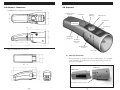
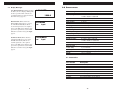
NOTES
CONTENTS
.....................................................
Page
01.0 Introduction . . . . . . . . . . . . . . . . . . . . . . . . . . . . . . . . . . . . . . . . . . . . . . . . .
1.1 Complete kit
02
02.0 Overview . . . . . . . . . . . . . . . . . . . . . . . . . . . . . . . . . . . . . . . . . . . . . . . .
2.1 Mounting stroboscope
2.2 Display Messages
03
03.0 Measuring RPM . . . . . . . . . . . . . . . . . . . . . . . . . . . . . . . . . . . . . . . . . .
3.1 Measuring true revolutions per minute (RPM)
3.2 Internal triggering mode
3.3 External triggering mode
3.4 Adjusting flash rate
3.5 Phase shift function
05
04.0 Tachometer Mode . . . . . . . . . . . . . . . . . . . . . . . . . . . . . . . . . . . . . . . . . . . . .
08
05.0 Flash tube replacement . . . . . . . . . . . . . . . . . . . . . . . . . . . . . . . . . . . . . . .
09
06.0 Charging the battery . . . . . . . . . . . . . . . . . . . . . . . . . . . . . . . . . . . . . . . . . .
11
07.0 Troubleshooting . . . . . . . . . . . . . . . . . . . . . . . . . . . . . . . . . . . . . . . . . . . . . .
12
08.0 Specifications . . . . . . . . . . . . . . . . . . . . . . . . . . . . . . . . . . . . . . . . . . . . . . . .
13
09.0 Appendix . . . . . . . . . . . . . . . . . . . . . . . . . . . . . . . . . . . . . . . . . . . . . . . . . . . . .
14
10.0 Warranty . . . . . . . . . . . . . . . . . . . . . . . . . . . . . . . . . . . . . . . . . . . . . . . . . . . . .
15
Direct view of the lamp may trigger an epileptic seizure.
Eye damage may result from improper use of the lamp.
WARNING
16
1
1.0 INTRODUCTION
10.0 WARRANTY
Stroboscopes are used in various applications, such as quality machine inspection and
timing. At high speed or high frequency operation the human eye cannot discern a
single image of a moving object.
Stroboscopes freeze these images by matching the speed of the moving object with
short duration flashes. An indicator or reference point, such as a small tape or paint
mark can be visually rotated in any direction depending on the phase angle and flash
rate it is subjected to.
The Electromatic DT-900 stroboscope has many of the same capabilities as our
DT-300 and DT-700 series stroboscopes, but is smaller.
1.1 Complete Kit
The DT-900 is supplied as a complete kit including:
•
•
•
•
DT-900 gauge
Charger
Spare lamp
Operating instructions
Additional parts such as sensors, holster and spare battery pack are sold
separately (see accessories on page 13). An optional carrying case is also
available. Please check with your dealer for more information.
Carrying Case (optional)
Strobe
ELECTROMATIC Equipment Co., Inc. (ELECTROMATIC) warrants to the
original purchaser that this product is of merchantable quality and confirms
in kind and quality with the descriptions and specifications thereof. Product
failure or malfunction arising out of any defect in workmanship or material in the
product existing at the time of delivery thereof which manifests itself within one
year from the sale of such product, shall be remedied by repair or replacement of
such product, at ELECTROMATIC’s option, except where unauthorized repair,
disassembly, tampering, abuse or misapplication has taken place, as determined
by ELECTROMATIC. All returns for warranty or non-warranty repairs and/or
replacement must be authorized by ELECTROMATIC, in advance, with all
repacking and shipping expenses to the address below to be borne by the purchaser.
THE FOREGOING WARRANTY IS IN LIEU OF ALL OTHER WARRANTIES,
EXPRESSED OR IMPLIED, INCLUDING BUT NOT LIMITED TO, THE
WARRANTY OF MERCHANTABILITY AND FITNESS FOR ANY PARTICULAR PURPOSE OR APPLICATION. ELECTROMATIC SHALL NOT BE
RESPONSIBLE NOR LIABLE FOR ANY CONSEQUENTIAL DAMAGE, OF
ANY KIND OR NATURE, RESULTING FROM THE USE OF SUPPLIED
EQUIPMENT, WHETHER SUCH DAMAGE OCCURS OR IS DISCOVERED
BEFORE, UPON OR AFTER REPLACEMENT OR REPAIR, AND WHETHER
OR NOT SUCH DAMAGE IS CAUSED BY MANUFACTURER’S OR
SUPPLIER’S NEGLIGENCE WITHIN ONE YEAR FROM INVOICE DATE.
Some State jurisdictions or States do not allow the exclusion or limitation of
incidental or consequential damages, so the above limitation may not apply to you.
The duration of any implied warranty, including, without limitation, fitness for any
particular
purpose and merchantability with respect to this product, is limited to the duration
of the foregoing warranty. Some states do not allow limitations on how long an
implied warranty lasts but, not withstanding, this warranty, in the absence of such
limitations, shall extend for one year from the date of invoice.
ELECTROMATIC Equipment Co., Inc.
600 Oakland Ave. Cedarhurst, NY 11516—USA
Tel: 1-800-645-4330/ Tel: 516-295-4300/ Fax: 516-295-4399
Battery Pack
Every precaution has been taken in the preparation of this manual. Electromatic Equipment Co., Inc.,
assumes no responsibility for errors or omissions. Neither is any liability assumed for damages resulting
from the use of information contained herein. Any brand or product names mentioned herein are used for
identification purposes only, and are trademarks or registered trademarks of their respective holders.
2
15
9.0 APPENDIX - DIMENSIONS
2.0 OVERVIEW
DT-900 dimensions with battery pack. Dimensions are in inches.
AC Adapter Charger
Connection
Power Button
Flash rate
divided by 2
Adjustment Dial
Mode Control
Flash Rate
multiplied by 2
Power Indicator
Rechargeable
Battery Pack
Easy tab for
Battery Pack
removal
External Triggering
Connector
Battery pack. Dimensions are in inches
Phase control
2.1 Mounting Stroboscope
To mount the strobe on a tripod (or any other mounting surface), use a 1/4-20unc
screw, 8mm long or shorter. Insert the screw into the mounting screw hole (see
photo below) and tighten.
Stroboscope
Battery Pack
Mounting Screw Hole 1/4 x 20 unc
14
3
8.0 SPECIFICATIONS
2.2 Display Messages
Low Battery Indicator will appear when
the battery needs recharging. Although the
stroboscope will continue to flash, it is
recommended that you charge the battery
when this message appears.
External Mode. When switched to
External Mode Triggering (see page 6),
the DT-900 automatically looks for
an external signal source. If a signal is
detected, the LED power indicator turns
green. If no signal is detected, the LED
will turn red, and the message no input
appears.
Tachometer Mode. When switched
to Tachometer Mode (see page 8), the
DT-900 automatically looks for an
external signal source. If a signal is
detected, the LED power indicator turns
green. If no signal is detected, the LED
will turn red, and the message no input
appears.
LOW BATT
1200.0
Ext.Mode
no
input
Flash rate range
40–12,500 flashes per minute (FPM)
Flash rate accuracy
± 0.5 FPM or ± 0.01% of reading, whichever is greater
Flash setting resolution
0.1 FPM for 100 to 9999 FPM,
1 FPM for 10,00 to 12,500 FPM
Flash tube
Xenon, 10W, user replaceable
Flash tube life
100 million flashes
Flash duration
9–15 µsec
Light power
154 mJoules per flash
Battery type
NiMH, rechargeable removable
Battery capacity
2.6 AmpHr
Battery charge time
2–4 hours, using supplied AC adapter
Run time per charge
2.5 hours at 1600 FPM, 1.25 hours at 3200 FPM
Battery charger AC input 115 VAC, 50/60 Hz
Tach.Mode
no
input
Display
8 character by 2 line LCD, alphanumeric
Display update
Continuous
Display resolution
0.1 FPM for 100 to 9999 FPM,
1 FPM for 10,000 to 12,500 FPM
Timebase
Crystal oscillator, 100 ppm accuracy
External trigger input
0–5V TTL type via stereo phone jack
External trigger
to flash delay
5 µsec maximum
Clock output
0–5V TTL type via stereo phone jack
Housing
Impact and oil resistant polycarbonate
Weight
1 lb., 7 oz. (650 g)
8.1 Accessories
4
Part Number
Description
FLASHTUBE900
Flash tube replacement
DT-900-1
Replacement battery
DT-900-2
AC adapter, 120V AC 60 Hz
DT-900-3
Lens replacement
DT-900-4
Handle pad replacement
DT-900-5
Plastic carrying case
DT-6
Holster, padded
DT-900-8
Universal AC adapter with world plugs
13
7.0 TROUBLESHOOTING
3.0 MEASURING RPM
FPM reading is displayed but unit is not flashing:
Flash tube may need to be replaced (See flash tube replacement section)
Stroboscope is in external trigger mode, with no flash:
•
•
•
•
Check flash tube.
Check sensor.
Check wire continuity.
Check phono connector wiring for a possible loose connection.
Stroboscope is in internal trigger mode, no flash:
• Check flash tube.
• Check battery and recharge if needed.
DT-900 Stroboscopes are DUAL function instruments that give the operator the illusion of “stopped motion” when in actuality the equipment under observation is in a
moving state. By adjusting the flash rate, equipment in motion appears to be standing
still. With a slight adjustment, movement can be viewed in apparent slow motion,
which enables the operator or observer to study the process in action. All Electromatic
stroboscopes can also measure rotational (RPM) or reciprocating (strokes per minute)
speeds with the same high precision as with an electronic digital tachometer.
3.1 To measure true revolutions per minute (RPM)
1. “Mark” the object to be measured by either visually noting an inherent
distinguishing characteristic (such as a label, scratch, etc.) or physically
marking the object with a small piece of tape, pencil mark, etc.
2. Turn power switch on.
3. Aim the light beam at the object under observation.
Stroboscope will not turn on completely
• Check battery, it may need to be charged.
NOTE:
The optimal distance between strobe and moving object is
approximately 2 feet.
• The DT-900 may have reached its Max. Flash Rate, triggering the auto shutoff
feature. The DT- 900 will shutoff after 60 seconds if no buttons are pressed,
or the dial knob is not turned. If the Max Flash rate is reached, allow a couple
of minutes to make adjustments.
4. Adjust flash rate from highest Flash Per Minute (FPM ) downward.
• Allow the unit to cool down if unit turns off due to high flash rate and
continuous operation.
6. To verify RPM reading, press ÷2. A single image should appear again.
5. The true RPM can be noted once the action appears frozen and the first
single image of the “mark” appears (see diagram below for further
explanation).
Red LED flashing from Battery while charging
• Continue charging, the battery has been drained below its safe charging level.
• Observe the LED indicator, it should stop flashing after a couple of minutes if
flashing does not stop charger can not recover battery by trickle charging. A
replacement is needed.
IMPORTANT: Remove battery pack prior to charging.
IF, AFTER PERFORMING THE ABOVE PROCEDURES, THE DT-900 IS STILL
NOT WORKING, CONTACT ELECTROMATIC FOR SERVICE INFORMATION.
12
5
6.0 CHARGING
3.2 Internal Triggering Mode
To use the DT-900 stroboscope in the Internal Triggering Mode:
1. Turn power switch on. The power indicator LED will light up.
2. Press the Mode Control button. Unless a sensor is connected to the external
signal connector, the display will read EXT.Mode No Signal. Press Mode
again, the display will read TachMode. Press Mode again to enter the
Internal Triggering Mode (no mode indicator is shown on the display).
3. Aim the light beam at object under observation. The optimal distance
between the strobe and moving object is approximately 2 feet.
THE
BATTERY
If the battery is low, the stroboscope will not turn on completely and the display will
eventually disappear.
It is recommended that you recharge the battery once the message “LOW BATT
flashes the display. Proceed as follows:
1. Turn power off.
2. Push the two tabs on the sides of the DT-900
to release the battery. Always remove the
battery from the DT-900 before charging.
4. Measure RPM by turning the Adjustment Dial to adjust the flashing rate to
the rotational speed of the object.
NOTE: To achieve a particular RPM or FPM quickly, use the x2 or
÷2 switches first, and then the dial for fine-tuning.
3.3 External Triggering Mode
To use the DT-900 stroboscope in external triggering mode:
1. Firmly plug in external sensor.
This unit accepts TTL Logic,
high of +5V and low of 0V.
2. Turn power switch on. The power
indicator will light up and the strobe
will automatically search for the presence of an external signal.
If found, the LED power indicator will turn green. If not found, the
indicator will turn red to indicate the absence of an external signal
and the message no input will appear on the display.
3. Press the Mode Control button until Ext.Mode appears on the display.
FPM
Tab Release
3. Insert AC adapter/charger plug into the strobe
receptacle.
CAUTION: Charge the unit only with the
AC adapter/charger provided by
Electromatic.
4. The LED indicator on the handle will light up,
indicating the battery is charging. Normal
charging time is 2 to 4 hours. It is strongly
recommended to charge the battery fully
before using. The LED light will turn off
after the battery is fully charged.
Flash indicator will flash in correspondence with input signal. The input
signal will be displayed as FPM (Flash per Minute).
Maximum 12,500 FPM, Minimum 15 FPM. If the maximum value is
exceeded the strobe will stop flashing, but the clock source frequency
will continue to be displayed.
Stereo Jack Connector
The phono connector is
3.5mm in diameter. The
tip is the signal output
from the strobe; and the
ring is the signal input to
the strobe. Electrically the
signals are TTL logic
levels, 0-5 V swing,
high impedance.
6
NOTE: The adapter/charger may NOT be used as a power supply to power the strobe
continuously. If the LED is flashing when the charger is plugged into the battery, it
means that the battery has been discharged below its safe charging level. The charger
will attempt to recover the battery by trickle charging. If it is successful, the charger
will continue with the regular charge time, otherwise it will continue flashing. If this
happens you may need to replace your battery pack.
11
4. Ensure the bulb is centered in the reflector.
5. Re-install the protective lens. Line up the four tabs of the lens with the four slots
of the strobe. Insert one tab in place, then press the lens back into the strobe
so that the remaining tabs snap into place.
3.4 Adjusting The Flash Rate
After turning on the strobe, you can adjust the flash rate in two ways
1. Turn the central Adjustment Dial to reach the desired rate. Turning the
dial counter clockwise to decreases the flash rate. Turning the dial clockwise
increases the flash rate. The faster you turn the dial, the faster the rate will
change. Flash step is 0.5 flash per turn.
2. Press the x2 and ÷2 buttons to increase or decrease the rate. Pressing the
x2 button doubles the current flash rate. For example, if the strobe is set to
1000 FPM, pressing the x2 button will change the rate to 2000 FPM.
Pressing the ÷2 button reduces the flash rate in half. For example, if the
strobe is set at 5000 FPM, pressing the ÷2 button will change the rate to
2500 FPM.
NOTE: If the x2 or ÷2 buttons are pressed and the calculated rate is beyond the
range of 40-12,500 FPM, the flash rate will be set to the limit of the
strobe. For example, if the strobe is set to 8000 FPM, pressing the
x2 button will change the rate to 12,500 FPM.
NOTE: The DT900 is limited by the following maximum FPM
Max Flash:
12,500 FPM
Min Flash:
40 FPM (Internal Triggering Mode)
Min Flash:
15 FPM (External Triggering Mode)
3.5 Phase Shift Function
The Phase Shift control button is used to read the angular delay or advancement
in degrees between the trigger signal and the actual speed of the moving object.
Phase shifting is used to examine the entire circumference of a gear or reciprocating machine while in operation. This important feature allows the operator to
examine the object in motion, providing a “real time” view for predictive and
preventive maintenance.
The operator can rotate the view by changing the phase of the strobe flash.
1. Lock onto the desired speed by adjusting the strobe flash rate until the object
appears stationary.
2. Enter the Phase Mode by pressing the Phase Control button. The display
will show Phase: 0 deg.
3. Rotate the Adjustment Dial counter clockwise to decrease the phase angle.
Turn the dial clockwise to increase the phase angle. The angle is changed
by five degrees by each step on the dial.
Alternatively, you can spin the phase angle using the x2 and ÷2 buttons. Hold
down the x2 button to spin positively through the phase angles. Hold down
the ÷2 button to spin negatively through the phase angles. Releasing the
button will stop and hold the last phase angle.
4. Press the Phase Control button again to exit the Phase Shift Mode and return
to normal operation.
10
7
5.0 FLASH TUBE
4.0 TACHOMETER MODE
When in the Tachometer Mode the strobe will not flash but can be used like a handheld tachometer. The DT-900 will display the frequency of the signal source connected
to it. To use the Tachometer Mode:
1.
Turn on the strobe and press the Mode Control button until TachMode appears
on the display.
2.
Connect a signal source to the external signal connector (See page 3)
using a stereo type phono connector (see page 5).
3.
If a valid signal source is detected, the DT-900 stroboscope LCD will display
the signal rate and the LED will be green.
4.
If no valid signal source is detected, the strobe will display TachMode – no
input and the LED will be red.
5.
When using the Tachometer Mode, the maximum signal rate is 59,000 FPM
and the minimum signal rate is 40 FPM.
REPLACEMENT
When an FPM reading is displayed, but the strobe is not flashing, the flash tube may
need to be replaced.
WARNING: The surface of the DT-900 stroboscope lens especially the bulb
can get hot during continued use. Caution should be taken to allow sufficient
cooling time before attempting to replace the bulb.
WARNING: The DT-900 stroboscope operates at High Voltage inside the
lamp and the electronic compartment. Please disconnect prior to lamp
replacement.
Insert screwdriver
into opening
6.
To exit the Tachometer Mode and return to normal strobe operation, disconnect
the signal source and press the Mode Control button once to enter the Internal
Triggering Mode.
Protective Lens
1. Remove the front lens from the strobe by inserting the
tip of a screwdriver into one of the vent holes. Gently
pry the lens out (Be careful not to damage the edge
of the lens.). Pry each side out, one by one until the
lens can be removed.
NOTE: The reflector does not need to be removed to
replace the bulb. It should remain in place.
2. Protect the bulb from any oil or residue by using a piece of cloth between your
fingers and the bulb. Grasp and pull the bulb to remove it.
3. Handle the new bulb with a piece of cloth. Insert the new bulb in the connector by
pressing it in place.
IMPORTANT: Be sure to orient the red dot on the bulb connector with the
red dot on the strobe connector. If the bulb is inserted backwards, it
will fail to operate as specified.
8
9
CHECK•LINE
BY ELECTROMATIC
HAND-HELD STROBOSCOPE
DT-900
CHECK•LINE ®
ELECTROMATIC
E
INSTRUMENTS
Q
U
I
P
M
E
N
T
C
O .,
I
N
C .
600 Oakland Ave., Cedarhurst, NY 11516–U.S.A.
TEL: 516-295-4300 • FAX: 516-295-4399
Operating Instructions
®


![Roostloggers [Titley] - An Introductory Manual](http://vs1.manualzilla.com/store/data/005649014_1-8c618e497bb2550a491bca85d50a292e-150x150.png)
![121290 CR-4000 Controller User Manual [English].pub](http://vs1.manualzilla.com/store/data/005770288_1-ff1b31ed544f6d88740c7f5db9da46b2-150x150.png)