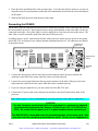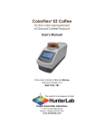
1
Artisan Technology Group is your source for quality new and certified-used/pre-owned equipment • FAST SHIPPING AND DELIVERY • TENS OF THOUSANDS OF IN-STOCK ITEMS • EQUIPMENT DEMOS • HUNDREDS OF MANUFACTURERS SUPPORTED • LEASING/MONTHLY RENTALS • ITAR CERTIFIED SECURE ASSET SOLUTIONS SERVICE CENTER REPAIRS Experienced engineers and technicians on staff at our full-service, in-house repair center WE BUY USED EQUIPMENT Sell your excess, underutilized, and idle used equipment We also offer credit for buy-backs and trade-ins www.artisantg.com/WeBuyEquipment InstraView REMOTE INSPECTION LOOKING FOR MORE INFORMATION? Visit us on the web at www.artisantg.com for more information on price quotations, drivers, technical specifications, manuals, and documentation SM Remotely inspect equipment before purchasing with our interactive website at www.instraview.com Contact us: (888) 88-SOURCE | [email protected] | www.artisantg.com D25 with DP-9000 A60-1003-140 Manual Version 2.2 An ISO 9001 Certified Company Artisan Technology Group - Quality Instrumentation ... Guaranteed | (888) 88-SOURCE | www.artisantg.com D25 with DP-9000 User's Manual October 2003 Hunter Associates Laboratory 11491 Sunset Hills Road Reston, Virginia 20190 A60-1003-140 Manual Version 2.2 Artisan Technology Group - Quality Instrumentation ... Guaranteed | (888) 88-SOURCE | www.artisantg.com Artisan Technology Group - Quality Instrumentation ... Guaranteed | (888) 88-SOURCE | www.artisantg.com Copyrights and Trademarks This documentation contains proprietary information of Hunter Associates Laboratory, Inc. Its reproduction, in whole or in part, without the express written consent of Hunter Associates Laboratory, Inc. is prohibited. IBM, IBM-PC, and PC/DOS are registered trademarks of International Business Machines Corporation. MS-DOS and Windows are registered trademarks of Microsoft Corporation. LOTUS 1-2-3 is a registered trademark of Lotus Development Corporation. Any references to "IBM-Compatible Equipment" may include trademarks of specific trademark holder(s). Please keep this manual in a safe place. HunterLab must charge a fee for replacement manuals. Artisan Technology Group - Quality Instrumentation ... Guaranteed | (888) 88-SOURCE | www.artisantg.com Artisan Technology Group - Quality Instrumentation ... Guaranteed | (888) 88-SOURCE | www.artisantg.com Safety Notes For your safety when using your color measurement equipment, you should pay particular attention to the following types of statements in the hardware section of this User’s Manual. Each description is shown in its representative typeface. Notice: General safety instruction that should be observed at all times while operating the instrument. CAUTION Specific safety instruction critical to the type of instrument operation being explained in the area of the manual where the caution appears. Note: Additional clarification of instructions, not safety-related. Artisan Technology Group - Quality Instrumentation ... Guaranteed | (888) 88-SOURCE | www.artisantg.com Artisan Technology Group - Quality Instrumentation ... Guaranteed | (888) 88-SOURCE | www.artisantg.com Table of Contents SYSTEM DESCRIPTION AND INSTALLATION INSTRUCTIONS ................... 1-1 The D25 Sensors.................................................................................................................................. 1-1 The DP-9000 Processor ...................................................................................................................... 1-3 Accessories........................................................................................................................................... 1-5 Options and Sample Devices.............................................................................................................. 1-6 Compression Cell Assembly (all models)......................................................................................... 1-7 Reduced Area View (A sensor)......................................................................................................... 1-8 Reduced Area View (L sensor) ......................................................................................................... 1-9 Ultraviolet-Absorbing Filter (all models) ......................................................................................... 1-9 Port Inserts (Standard Round Opening; A, M sensors)................................................................... 1-10 Port Insert for Capsules (A sensor) ................................................................................................. 1-11 Port Insert for 2.5-inch Sample Cup and 2.5-inch Sample Cup (A, M sensors) ............................. 1-11 Sample Cup Opaque Cover (A, M sensors) .................................................................................... 1-11 Ring and Disk Set (A. M sensors)................................................................................................... 1-11 Sample Cup Assembly (L sensor)................................................................................................... 1-12 Replacement Glass or Plastic Window for Sample Cup Assembly (L sensor)............................... 1-13 Replacement Glass or Plastic Insert for Sensor Port (L sensor) ..................................................... 1-14 Glass or Plastic-Bottom Sample Cup (L sensor)............................................................................. 1-14 Replacement Glass or Plastic Window for Sample Cup (L sensor)................................................ 1-15 5-inch Glass Sample Cup (L sensor)............................................................................................... 1-15 Cover Glass, Rectangular (L sensor)............................................................................................... 1-15 Replacement or Upgraded DP-9000 Memory Board (all models).................................................. 1-16 Tomato Product Scores (A sensor).................................................................................................. 1-18 TAPPI Brightness (A sensor).......................................................................................................... 1-19 DP-9000 Utility Software................................................................................................................ 1-19 Installation of the D25 DP-9000 System ......................................................................................... 1-20 Mounting the Sensor ....................................................................................................................... 1-20 Connecting the DP-9000 ................................................................................................................. 1-21 INSTRUMENT AND PRODUCT SETUP .................................................................. 2-1 Instrument Setup Parameters ........................................................................................................... 2-1 Language ........................................................................................................................................... 2-2 Baud Rate .......................................................................................................................................... 2-2 Data Bits............................................................................................................................................ 2-2 Parity ................................................................................................................................................. 2-2 Data Format....................................................................................................................................... 2-2 Print Mode......................................................................................................................................... 2-2 Data Logging Mode .......................................................................................................................... 2-3 Setups ................................................................................................................................................ 2-3 Date ................................................................................................................................................... 2-3 Time .................................................................................................................................................. 2-3 Calibration Interval ........................................................................................................................... 2-3 Standby Delay ................................................................................................................................... 2-3 Diagnostics ........................................................................................................................................ 2-3 i Artisan Technology Group - Quality Instrumentation ... Guaranteed | (888) 88-SOURCE | www.artisantg.com Instructions for Instrument Setup .................................................................................................... 2-6 Setup Mode ....................................................................................................................................... 2-6 Instrument Setup ............................................................................................................................... 2-8 Diagnostics ........................................................................................................................................ 2-9 Product Setup Parameters ............................................................................................................... 2-15 Setup................................................................................................................................................ 2-15 Name ............................................................................................................................................... 2-15 Display ............................................................................................................................................ 2-16 Read Interval ................................................................................................................................... 2-16 Sample ID........................................................................................................................................ 2-16 Average ........................................................................................................................................... 2-16 Statistics .......................................................................................................................................... 2-16 Color Scale ...................................................................................................................................... 2-16 Color Index...................................................................................................................................... 2-16 Color Differences Scale .................................................................................................................. 2-16 Color Difference Index ................................................................................................................... 2-17 CMC Ratio ...................................................................................................................................... 2-17 CMC Commercial Factor ................................................................................................................ 2-17 Standard........................................................................................................................................... 2-17 Target Values .................................................................................................................................. 2-17 Tolerances ....................................................................................................................................... 2-18 Instructions for Product Setup........................................................................................................ 2-19 Setup Mode ..................................................................................................................................... 2-19 Product Setup .................................................................................................................................. 2-20 OPERATION.................................................................................................................. 3-1 Standardizing ...................................................................................................................................... 3-1 Taking Readings ................................................................................................................................. 3-2 Read Mode ........................................................................................................................................ 3-2 Taking Readings................................................................................................................................ 3-3 LESSONS........................................................................................................................ 4-1 Lesson 1: Using the Working Standard........................................................................................... 4-2 Lesson 2: Using the Physical Standard............................................................................................ 4-4 Lesson 3: Using the Numerical Standard ........................................................................................ 4-6 Lesson 4: Using the Hitch Standard ................................................................................................ 4-9 Lesson 5: Using the Duplicate Standard ....................................................................................... 4-11 Lesson 6: Averaging with Statistics ............................................................................................... 4-14 Lesson 7: Measuring Opacity ......................................................................................................... 4-16 Lesson 8: Automatically Generating Tolerances .......................................................................... 4-18 Lesson 9: Using an Alternate White Standard ............................................................................. 4-20 Lesson 10: Using a Serial Printer................................................................................................... 4-22 Printing and Clearing Stored Readings ........................................................................................... 4-22 Printing Setup Data ......................................................................................................................... 4-22 The Print Measurement Screen Function ........................................................................................ 4-22 Lesson 11: Using the TAPPI Brightness Option (A sensor only) ................................................ 4-24 Lesson 12: Using the Tomato Product Scores Option (A sensor only) ....................................... 4-26 ii Artisan Technology Group - Quality Instrumentation ... Guaranteed | (888) 88-SOURCE | www.artisantg.com MEASUREMENT GUIDELINES................................................................................ 5-1 Selecting, Preparing, and Presenting Samples................................................................................. 5-1 More on Sample Presentation to the Instrument ............................................................................ 5-1 Tolerances............................................................................................................................................ 5-3 The Datalog ......................................................................................................................................... 5-4 Averaging Data ................................................................................................................................... 5-5 Displaying Data................................................................................................................................... 5-6 Standby................................................................................................................................................ 5-7 Read Interval....................................................................................................................................... 5-8 Standardizing ...................................................................................................................................... 5-9 MAINTENANCE ........................................................................................................... 6-1 Operating Conditions ......................................................................................................................... 6-1 Power Requirements ......................................................................................................................... 6-1 Environment ...................................................................................................................................... 6-1 Environmental Conditions that May Cause Problems ...................................................................... 6-1 Changing the Source Lamp ............................................................................................................... 6-3 The A Sensor..................................................................................................................................... 6-3 The M and L Sensors ........................................................................................................................ 6-4 Changing the Fuses............................................................................................................................. 6-7 Changing the Printer Paper............................................................................................................... 6-8 Adjusting Display Contrast ............................................................................................................... 6-9 Cleaning the Instrument Standards................................................................................................ 6-11 Cleaning the Sensor and Processor................................................................................................. 6-12 Adjusting Incident Beam Optics ..................................................................................................... 6-13 D25A Sensors.................................................................................................................................. 6-13 D25L and D25M Sensors................................................................................................................ 6-15 Performing Diagnostics.................................................................................................................... 6-16 Resetting the DP-9000 ...................................................................................................................... 6-17 SPECIFICATIONS........................................................................................................ 7-1 Physical Characteristics ..................................................................................................................... 7-1 Environment ...................................................................................................................................... 7-1 Power Required .................................................................................................................................. 7-2 Conditions of Illumination and Viewing .......................................................................................... 7-3 Instrument Performance.................................................................................................................... 7-4 Regulatory Notice ............................................................................................................................... 7-5 INSTRUMENT REPLACEMENT, REPAIR, PROBLEMS, AND QUESTIONS . 8-1 Warranty ............................................................................................................................................. 8-1 Shipping Claims.................................................................................................................................. 8-2 Breakage or Damage ......................................................................................................................... 8-2 Shortage............................................................................................................................................. 8-2 Incorrect Shipment ............................................................................................................................ 8-3 Returns ................................................................................................................................................ 8-4 When You Need Assistance ............................................................................................................... 8-5 iii Artisan Technology Group - Quality Instrumentation ... Guaranteed | (888) 88-SOURCE | www.artisantg.com MEASUREMENT VALUES......................................................................................... 9-1 Color Scales and Related Color Difference Scales and Color Difference Indices ........................ 9-1 CIE Tristimulus XYZ Scale .............................................................................................................. 9-1 CIE Chromaticity Coordinates, Yxy ................................................................................................. 9-1 Opponent-Color Scales (Hunter Lab, CIE 1976 L*a*b*, and CIE LCh) ......................................... 9-1 Hunter Rdab Color Scale................................................................................................................... 9-4 Other Color Difference Scales ........................................................................................................... 9-5 FMC-2 (Friele - MacAdam - Chickering) Color Difference............................................................. 9-5 Other Color Difference Indices ......................................................................................................... 9-6 ∆Ec (CMC)........................................................................................................................................ 9-6 Color Indices ....................................................................................................................................... 9-8 457 nm Brightness............................................................................................................................. 9-8 Opacity .............................................................................................................................................. 9-8 TAPPI Brightness (optional)............................................................................................................. 9-8 Tomato Scores (optional) .................................................................................................................. 9-8 Whiteness Index E313..................................................................................................................... 9-10 Yellowness Indices.......................................................................................................................... 9-11 Paper Brightness (Z%) .................................................................................................................... 9-11 COMMUNICATIONS...................................................................................................A-1 Host Communication......................................................................................................................... A-1 Simple Output of Data ...................................................................................................................... A-3 Sending DP-9000 Data to Windows 95, 98, 2000, and NT Spreadsheets ....................................... A-3 LESSON SETUPS..........................................................................................................B-1 Lesson 1 Using the Working Standard.............................................................................................B-1 Lesson 2 Using the Physical Standard .............................................................................................B-1 Lesson 3 Using the Numeric Standard.............................................................................................B-2 Lesson 4 Using the Hitch Standard ..................................................................................................B-2 Lesson 5 Using the Duplicate Standard ...........................................................................................B-2 Lesson 6 Averaging with Statistics ..................................................................................................B-3 Lesson 7 Measuring Opacity............................................................................................................B-4 Lesson 8 Automatically Generating Tolerances ..............................................................................B-4 Lesson 9 Using an Alternate White Standard ..................................................................................B-4 Lesson 10 Using a Serial Printer ......................................................................................................B-4 Lesson 11 Using the TAPPI Brightness Option...............................................................................B-4 Lesson 12 Using the Tomato Product Scores Option ......................................................................B-5 GLOSSARY....................................................................................................................C-1 REFERENCES ...............................................................................................................D-1 iv Artisan Technology Group - Quality Instrumentation ... Guaranteed | (888) 88-SOURCE | www.artisantg.com System Description and Installation Instructions Notice: Use of this equipment in a manner not specified by the manufacturer may impair the protection afforded by the equipment. The D25 system consists of a D25 optical sensor on a stand and a DP-9000 processor. Both the sensor and the processor are labeled with serial number tags. The D25 Sensors In the D25 optical sensor, light from a quartz halogen cycle lamp is directed at the specimen at an angle of 45° from the perpendicular. The reflected light is then collected in a receptor located directly above (or below, depending on the orientation of the sensor) the specimen at 0° from the perpendicular. The electrical signals in the receptor are then directed to the processor. There are three types of D25 sensors. All the sensors have a viewing aperture on the front of the cover so that you may accurately position the desired area of the sample over the measurement port. A tag containing model information and the instrument serial number is located on the right side of the sensor when it is mounted port up. • The A sensor (shown below mounted port up) has a specimen port area of two inches (51 mm) in diameter. The specimen is illuminated from two directions (bidirectionally) and the illuminated area is slightly smaller than the port opening. 10/03 System Description and Installation Instructions Artisan Technology Group - Quality Instrumentation ... Guaranteed | (888) 88-SOURCE | www.artisantg.com 1-1 Viewing aperture Specimen port Model and serial number tag • The D25A sensor The L sensor (shown below mounted port up) has a specimen port area of 3.75 inches (95 mm) in diameter. The specimen is illuminated from all sides (circumferentially) and the port opening is completely flooded with light. Specimen port Viewing aperture Model and serial number tag • 1-2 The D25L with DP-9000 The M sensor, which is similar in appearance to the L sensor, has a specimen area two inches (51 mm) in diameter. The specimen is illuminated from all sides. System Description and Installation Instructions Artisan Technology Group - Quality Instrumentation ... Guaranteed | (888) 88-SOURCE | www.artisantg.com 10/03 The DP-9000 Processor The DP-9000 processor shown below converts the signals from the optical sensor into color values relative to the C illuminant and 2° standard observer. These values are displayed on the 8-line by 40column liquid crystal display (LCD) screen. All operations of the system are easily executed from the control panel which contains six function keys and four arrow keys. This control panel is shown below. The processor also contains a covered internal printer for printing color measurements and other data. The on-board memory of the processor holds up to 99 product standards and can store up to 400 measurements. A bi-directional RS-232C serial communications port is also included to allow output of data to a 200-column serial printer or computer. The model and serial number for the system is located on the instrument tag on the back of the processor. Printer LCD screen Control panel The DP-9000 processor The DP-9000 control panel 10/03 System Description and Installation Instructions Artisan Technology Group - Quality Instrumentation ... Guaranteed | (888) 88-SOURCE | www.artisantg.com 1-3 Instrument tag The back of the DP-9000 processor Fuses RS-232C port On/off switch 1-4 System Description and Installation Instructions Artisan Technology Group - Quality Instrumentation ... Guaranteed | (888) 88-SOURCE | www.artisantg.com 10/03 Accessories The following accessories are provided with the D25 system and can be found in the standards case: • • • • • • • • • • • • • Black glass - placed at the reflectance port during standardization. White calibrated tile - placed at the reflectance port during standardization. Colored tiles - used to check instrument performance. Tile data sheet - gives calibration information for standard tiles. Standards care card - gives instructions on how to clean all of the ceramic standards. Hex-head wrench set. Trimpot adjustment tool. Lens brush. Lens wipes. Fuse - 2 two-amp fuses are provided as spares. Lamp - one lamp is provided as a spare. Printer paper - two rolls are provided. Certificate of traceability of the standard tiles. 10/03 System Description and Installation Instructions Artisan Technology Group - Quality Instrumentation ... Guaranteed | (888) 88-SOURCE | www.artisantg.com 1-5 Options and Sample Devices Any or all of the following options and sample devices may be included. HunterLab part numbers are included for your convenience. • • • • • • • • • • • • • • • • • • • 1-6 Compression cell assembly (all models) [HL#02-8909-01 for A and M sensors, 02-8909-03 for L sensor], Reduced area view (A sensor) [HL#D25-RAI], Reduced area view (L sensor) [HL#D25-RAL], Ultraviolet-absorbing filter (all models) [HL#D25-UVA for A sensor, D25-UVM for L and M sensors], Port inserts (standard round opening; A, M sensors) [Various part numbers], Port insert for capsules (A sensor) [HL#04-6620-01], Port insert for 2.5-inch sample cup [HL#04-6622-00] and 2.5-inch sample cup (A, M sensors) [HL#04-7209-00], Sample cup opaque cover (A, M sensors) [HL#04-4000-00], Ring and disk set (A, M sensors) [HL#02-4579-00], Sample cup assembly (L sensor) [HL#02-8606-00 for plastic, 02-8601-01 for glass], Replacement glass or plastic window for sample cup assembly (L sensor) [HL#A04-1002-921 for glass, A04-1001-307 for plastic], Replacement glass or plastic insert for sensor port (L sensor) [HL#A04-1003-233 for glass, A041002-941 for plastic], Glass or plastic-bottom sample cup (L sensor) [HL#L02-1008-437 for plastic, L02-1008-436 for glass], Replacement glass or plastic window for sample cup (L sensor) [HL#A04-1001-308 for plastic, A04-1002-920 for glass], 5-inch (127-mm) glass sample cup (L sensor) [HL#04-7767-00], Cover glass, rectangular (L sensor) [HL#12-0001-20], Replacement or upgraded DP-9000 memory board (all models) [Various part numbers], Tomato product scores (A sensor) [HL#D25-TPC or D25-TPC/2001], TAPPI Brightness (A sensor) [HL#D25-2BT], System Description and Installation Instructions Artisan Technology Group - Quality Instrumentation ... Guaranteed | (888) 88-SOURCE | www.artisantg.com 10/03 • DP-9000 Utility Software [HL#DP-UTIL]. Compression Cell Assembly (all models) This option is used for compressing fibers into a compact mass to permit repeatable color measurement. The compression cell assembly consists of: • • Port insert, • Glass 2.5-inch (64-mm) sample cup, • Specimen block (needed for D25L only), Compression cell. To install and operate the compression cell assembly, 1. Remove the original port insert (and specimen block, if included) and replace it with the counterbored port insert (and specimen block) supplied with the compression cell set. 2. Standardize the instrument. 3. Place the sample material into the sample cup and place the cup into the cup holder on the bottom half of the compression cell. 4. Place the compression arm over the cup holder and twist the arm counter-clockwise until it locks into the detents. The red lever on the arm should be pointing down. 5. Supply clean, filtered, compressed air to the compression cell through the 1/8 NPT air fitting at the top of the arm. The maximum air pressure to be used is 50 psi. 6. Carefully move the red lever up until the plunger pushes the sample material firmly against the bottom of the sample cup. 7. Place the lip on the bottom of the compression cell into the counterbored port insert and proceed with sample measurements. 8. Remove the compression cell from the instrument and press the red lever down to retract the plunger. 10/03 System Description and Installation Instructions Artisan Technology Group - Quality Instrumentation ... Guaranteed | (888) 88-SOURCE | www.artisantg.com 1-7 9. Open the compression cell, remove the sample cup, and continue with measurement of additional samples. Reduced Area View (A sensor) The reduced area view option for the A sensor provides turnable lenses to reduce the sample area illuminated to a 1/2-inch (13-mm) diameter, and a port insert with a 1/2-inch (13-mm) diameter opening. When using this option, samples should be measured as quickly as possible to reduce the chance of fading due to the increased intensity of the illumination. Note: The reduced area view port should be used ONLY for color difference measurements. To reduce the view area, 1. Turn the two pointer knobs on the front of the sensor so that both reducing lenses are rotated into the beams. Both knobs should be pointing toward the center of the sensor. Use the specimen viewing aperture to observe the change. 2. Remove the standard 2-inch port insert by pulling it out of the port insert retainer. Replace it with the 1/2-inch diameter port insert. Be sure that the flat portion of the insert is facing outward with the beveled portion toward the sensor interior. 3. Standardize the instrument. Any change in port size must be followed by standardization on both the black glass and the white tile. All regular calibration checks of the instrument should be done using the normal beam intensity and the two-inch diameter port insert. The change of geometry that occurs when the reducing lenses are placed in the beams will cause a slight shift in the color values of the calibration standards. The reducing lenses also make the instrument more sensitive to any nonuniformity in standards or samples. To ensure repeatability of measurements, extra care should be taken when using the reducing lenses to measure the same spot on the sample or standard if multiple measurements are averaged. The surfaces of the reducing lenses can be easily damaged. If cleaning is required, use a light brush or lens cleaner. Any lubrication of the mechanism should be done sparingly since oil film caused by vaporization of lubricant inside the optical sensor increases the rate of dust contamination. Note: The hole of your port plate may be slightly larger than the size stated. This is correct and provides a “viewed area” of the stated size. 1-8 System Description and Installation Instructions Artisan Technology Group - Quality Instrumentation ... Guaranteed | (888) 88-SOURCE | www.artisantg.com 10/03 Reduced Area View (L sensor) The reduced area view option for the L sensor provides a 2-inch (51-mm) diameter port insert and a specimen block to reduce the area viewed to two inches. No other optical changes to the instrument are required. Note: The reduced area view port should be used ONLY for color difference measurements. To install the reduced area view port insert, press the insert into the counterbore until it locks into place. Be sure to position the port insert so that the flat side of the insert is facing away from the instrument. The insert extends 1/16” beyond the sensor sample plate. Note: The hole of your port plate may be slightly larger than the size stated. This is correct and provides a “viewed area” of the stated size. Ultraviolet-Absorbing Filter (all models) This attachment to the optical sensor consists of a pale yellow ultraviolet (UV)-absorbing filter on a rotatable mount. It is gear-driven from a shaft and operates by means of a pointer knob located near the port of the M and L sensors and on the front of the A sensor. For some applications, the elimination of fluorescence in a measurement is important. Fluorescence is caused by UV excitation of the sample, where a material absorbs nonvisible wavelengths of energy and re-emits this energy as light in the visible spectrum. Since UV light is part of the normal sample illumination, measurements may include UV excitation. To eliminate fluorescence from the measurement, a UV filter is placed in the light path of the tungsten source. With this option, a pair of UV-absorbing filters on a rotating mount can be used to exclude UV light from the specimen illumination. When the filter is positioned in the light path, the energy present in the lamp below 418 nm is virtually eliminated. The instrument should be standardized in this configuration before measurements are made. For optimum stability, the UV filter should be in the source path for ten minutes before standardization. The filter must be removed from the light path after use to prevent degradation. It is necessary to know what type of fluorescence is involved in the samples being measured. Some materials fluoresce due to excitation by visible rather than ultraviolet wavelengths. A UV-absorbing filter does not eliminate this type of fluorescence. Installation of the UV filter must be performed at the factory as part of the manufacturing process. To position the filter in the light beam and thus exclude the UV, turn the pointer to the “UV EXCLUDED” position. Standardize the instrument. To remove the filter from the light beam, move the pointer to the “UV INCLUDED” position. When the UV filters are removed from the beam, the instrument must be restandardized. Note: Do not leave the UV-absorbing filters in the light beam any longer than necessary. The filter material may fade with long-term exposure to high-level source illumination. 10/03 System Description and Installation Instructions Artisan Technology Group - Quality Instrumentation ... Guaranteed | (888) 88-SOURCE | www.artisantg.com 1-9 The surface of the UV filters should be cleaned by brush or lens cleaner. Any lubrication of the mechanism should be done sparingly since oil film caused by vaporization of lubricant inside the optical sensor increases the rate of dust contamination. Port Inserts (Standard Round Opening; A, M sensors) Special port plate inserts with various-sized openings are available for use with samples of differing sizes. Some inserts are also available with glass covers to protect the inside of the instrument from sample and airborne particles. Note: Performance specifications, such as factory-supplied color values, stability, and accuracy, are based on the standard port size and may not be achieved with a smaller port size or a glass-covered port. To install a port insert, 1. Remove the standard port insert by pulling it out of the port insert retainer. Replace it with the desired port insert. Make sure that the flat portion of the insert is facing outward with the beveled portion toward the interior of the sensor. 2. Standardize the instrument. Any change in port size must be followed by standardization on both the black glass and the white tile. When using a glass cover, standardize the instrument with the glass in place. However, you should check measurements of the colored tiles and perform any other diagnostics without the glass cover. Difference measurements using a glass cover will be more accurate than absolute measurements. Note: The hole of your port plate may be slightly larger than the size stated. This is correct and provides a “viewed area” of the stated size. 1-10 System Description and Installation Instructions Artisan Technology Group - Quality Instrumentation ... Guaranteed | (888) 88-SOURCE | www.artisantg.com 10/03 Port Insert for Capsules (A sensor) This option provides a port insert with an oblong port opening for use when measuring elongated specimens such as capsules. The size of the opening is 1/4 inch x 3/4 inch (6 mm x 19 mm). This option requires that the reduced area view be available and in use. Port Insert for 2.5-inch Sample Cup and 2.5-inch Sample Cup (A, M sensors) Sample cup This port insert is specially designed to accommodate the 2.5-inch (64mm) glass sample cup. The sample cup is ideal for the analysis of powders, granules, pellets, and translucent samples. Fill the cup with sample and then measure the sample through the bottom of the sample cup with the instrument in the port-up orientation. Sample cup port insert Sample Cup Opaque Cover (A, M sensors) The opaque cover provides a light trap to exclude the interference of external light on the 2.5-inch sample cup. It is placed over the filled cup at the reflectance port. Ring and Disk Set (A, M sensors) The ring and disk set is a plastic ring and ceramic disk for use inside the 2.5-inch (64-mm) glass sample cup. The ring and disk set are used for translucent liquids or semi-solids to exclude external light and provide a consistent white background. Insert the plastic ring into the cup, fill the cup with sample, and cover the sample with the ceramic disk. You may cover the entire assembly with an opaque cover, if desired. Measure the sample through the bottom of 10/03 System Description and Installation Instructions Artisan Technology Group - Quality Instrumentation ... Guaranteed | (888) 88-SOURCE | www.artisantg.com 1-11 the sample cup with the instrument in the port-up orientation. Sample Cup Assembly (L sensor) This option provides a sample cup and related items used to prepare a sample for measurement on a D25L optical sensor. A typical application for this option is averaging measurements of chips, cookies, and other textured food items. This option also includes modifications necessary to protect the sensor from potential ingress of oils and other ingredients normally associated with the preparation of food. For this application the sample may be placed into the large sample cup and the lid placed over the sample. The cup is then placed onto the instrument measurement port with the D25L optical sensor in the port-up position. The sample cup has three colored indicator marks which are used to orient the sample for sample averaging. The positioning marks on the cup allow for measurements of three unique areas of the sample. This option consists of: • • Specimen block, • Cover for the sample cup, • 6.5-inch (165-mm) sample cup with polycarbonate or glass bottom, 5.75-inch (146-mm) diameter light trap. Note: The pictures below are not scaled to each other. Specimen block Sample cup cover Sample cup Sample cup assembly Light trap 1-12 System Description and Installation Instructions Artisan Technology Group - Quality Instrumentation ... Guaranteed | (888) 88-SOURCE | www.artisantg.com 10/03 Install the assembly as follows: 1. Mount the optical sensor in the port-up position. 2. Locate the two push-button fasteners at the corners of the optical sensor's standard sample cup assembly (if there is one). 3. Press and release the push-button fasteners to unfasten the sample cup assembly. 4. Lift the sample cup assembly from the optical sensor. 5. Place the sample cup assembly provided with this option on the optical sensor with its opening toward the front of the instrument. The two pegs on the sample cup assembly fit into the holes outside the port opening. 6. Remove the protective paper from the sample cup provided with this option and proceed with standardization. Standardize the instrument using the light trap in place of the black glass, and then perform measurements as described below. 1. Fill the sample cup with sample material. 2. Place the cover on the cup and turn it to keep it in place. Be careful not to compress the sample with such force as to damage the bottom of the sample cup. 3. Slide the sample cup into the sample cup assembly and orient it so that one of the colored indicators is facing forward and aligned with the front of the instrument. 4. Take a sample measurement. 5. Rotate the cup so that another colored indicator is aligned forward. 6. Take a sample measurement. 7. Rotate the cup so that the third colored indicator is aligned forward. 8. Take a sample measurement. 9. Remove the cup from the sample cup assembly. Replacement Glass or Plastic Window for Sample Cup Assembly (L sensor) This option provides a replacement glass or plastic window for the specimen block window. To install the replacement window, 1. Using rubbing alcohol, clean the sample cup assembly's counterbored area where the window is placed. This area must be free of dust, dirt, adhesives, and other contaminants. 2. Apply a medium-sized bead of sealant around the counterbore in the sample cup assembly. 10/03 System Description and Installation Instructions Artisan Technology Group - Quality Instrumentation ... Guaranteed | (888) 88-SOURCE | www.artisantg.com 1-13 3. Clean the surface of the window with glass cleaner and a non-abrasive cotton or paper towel. 4. Place the window onto the counterbore and press firmly until the sealant covers the entire counterbored surface. Rotate the window back and forth slightly while pressing it into the counterbore. At this point, the window should sit approximately 0.010” below the surface of the sample cup assembly. Otherwise, try pressing the window into the counterbore. If this does not work, remove the window from the sample cup assembly and restart this procedure at the first step, paying particular attention to cleaning the counterbore area. 5. Using a cotton swab moistened with isopropyl alcohol, remove the excess sealant from the inside and outside of the sample cup assembly. 6. Allow the sealant to dry for twenty-four hours. 7. Clean both sides of the window using glass cleaner and a non-abrasive cotton or paper towel. Replacement Glass or Plastic Insert for Sensor Port (L sensor) Install the replacement insert as follows: 1. Remove the protective paper from the window insert. 2. Fit the window insert into the 5-inch (127-mm) diameter sensor opening with the ridge of the insert on the inside of the sensor and the flat side of the insert on the outside of the sensor as shown in the figure below. Glass or Plastic-Bottom Sample Cup (L sensor) This option provides a replacement 6.5-inch (165-mm) polycarbonate or glass sample cup. Fill the cup with sample and cover if desired, then slide it into the sample cup assembly on the top of the sensor. Read the sample. 1-14 System Description and Installation Instructions Artisan Technology Group - Quality Instrumentation ... Guaranteed | (888) 88-SOURCE | www.artisantg.com 10/03 Replacement Glass or Plastic Window for Sample Cup (L sensor) This option provides a replacement glass or plastic window for the glass or plastic sample cup. To install the replacement window, 1. Using rubbing alcohol, clean the sample cup's counterbored area where the window is placed. This area must be free of dust, dirt, adhesives, and other contaminants. 2. Apply a medium-sized bead of sealant around the counterbore in the sample cup. 3. Clean the surface of the window with glass cleaner and a non-abrasive cotton or paper towel. 4. Place the window onto the counterbore and press firmly until the sealant covers the entire counterbored surface. Rotate the window back and forth slightly while pressing it into the counterbore. At this point, the window should sit approximately 0.010” below the surface of the sample cup. Otherwise, try pressing the window into the counterbore. If this does not work, remove the window from the sample cup and restart this procedure at the first step, paying particular attention to cleaning the counterbore area. 5. Using a cotton swab moistened with isopropyl alcohol, remove the excess sealant from the inside and outside of the sample cup. 6. Allow the sealant to dry for 24 hours. 7. Clean both sides of the window using glass cleaner and a non-abrasive cotton or paper towel. 5-inch Glass Sample Cup (L sensor) A 5-inch (127-mm) sample cup is ideal for the analysis of large granular products and foods. Place the filled cup at the reflectance port. Cover Glass, Rectangular (L sensor) This option includes a 4-inch (102-mm) square port cover glass to prevent dust and sample material from contaminating the inside of the sensor. 10/03 System Description and Installation Instructions Artisan Technology Group - Quality Instrumentation ... Guaranteed | (888) 88-SOURCE | www.artisantg.com 1-15 Replacement or Upgraded DP-9000 Memory Board (all models) Follow the instructions below if installation of a new DP-9000 memory board is required. Before replacing the board, enter the Diagnostics mode, select Lamp Set-up, and note the lamp current and voltage. You may also want to print out all the setups you have created as they must be re-entered after the memory board has been replaced. All the setups can be printed by entering the Setup mode and pressing and holding the Print key until the DP-9000 double-beeps. Please note that only the active setups with DISPLAY set to ABSOLUTE or DIFFERENCE are printed. To install the memory board: 1. Turn off the power to the DP-9000 processor. 2. Loosen the two silver thumbscrews on the back of the processor. 3. Lift the cover from the processor. 4. Locate the vertical memory board directly behind the display screen. 1-16 System Description and Installation Instructions Artisan Technology Group - Quality Instrumentation ... Guaranteed | (888) 88-SOURCE | www.artisantg.com 10/03 Front view Side view 5. Loosen the thumbscrew at the top of the board-retaining clip to release the memory board. Front view Side view 6. Gently tilt the screw and the board-retaining clip away from the board. 10/03 System Description and Installation Instructions Artisan Technology Group - Quality Instrumentation ... Guaranteed | (888) 88-SOURCE | www.artisantg.com 1-17 7. Grasp the memory board firmly and rock it to release it from the connector which holds it to the processor board. Front view Side view 8. Ground yourself by touching a metal surface on the processor and then remove the new memory board from the anti-static bag. 9. Orient the board with the components facing toward the front of the processor and seat the board on the connector to the processor board. 10. Tighten the thumbscrew at the top of the board-retaining clip to hold the board securely in place. 11. Replace the processor cover and tighten the thumbscrews. 12. Return power to the DP-9000 processor and allow two hours for the system to warm up. After the board has been installed, and the warm-up period has elapsed, standardize the instrument and verify measurements of the white and colored tiles. You may also enter the Diagnostics mode and select Lamp Set-up to verify that the current and voltage are the same as before the board was installed. After you have verified the proper installation of the board you may re-enter your product setups. Tomato Product Scores (A sensor) The following tomato indices are included with the option: produce color (TC), tomato juice (TJS), processed products (TPS), tomato sauce (TSS), tomato catsup (TCS), and a/b ratio. This option also includes a special port insert, a 2.5-inch (64-mm) sample cup, and a tomato hitch tile. Use of the tomato score option is described in greater detail in Lesson 12 in Chapter 4 and the differences between the two available types of tomato scores is explained in the “Measurement Values” chapter. 1-18 System Description and Installation Instructions Artisan Technology Group - Quality Instrumentation ... Guaranteed | (888) 88-SOURCE | www.artisantg.com 10/03 TAPPI Brightness (A sensor) This option provides the TAPPI Brightness index and a special filter that must be in place when TAPPI measurements are made. The reduced area view option must also be available and in use when TAPPI Brightness is measured. Use of the TAPPI Brightness option is described in greater detail in Lesson 11 in Chapter 4. DP-9000 Utility Software The DP-9000 Utility Software is a DOS-based program that allows creation and storage of product setups, data manipulation and storage, as well as control of D25 operation from a personal computer. Use of this program is described in its separate user’s manual. 10/03 System Description and Installation Instructions Artisan Technology Group - Quality Instrumentation ... Guaranteed | (888) 88-SOURCE | www.artisantg.com 1-19 Installation of the D25 DP-9000 System For best performance, your instrument should be placed where there is ample work space with medium or subdued illumination and no drafts. For optimum results, a clean, air-conditioned area is recommended with a relative noncondensing humidity of less than 85% and relatively constant temperature between 50° F and 122° F (14 - 50° C). The instrument should be connected to a stable, instrument-grade power line. If other equipment is connected to the same power line, a transient power surge may be produced when the other equipment is turned on. If this happens, restandardize the instrument before making measurements. HunterLab recommends using a line conditioner with a minimum 600 VA rating and a battery back-up system. The following instructions guide you through the initial installation of your D25 DP-9000 system. First, mount the sensor in the desired position, with the specimen port either up or down, and then make the required connections between the sensor and the processor. Mounting the Sensor The sensor can be mounted directly over the processor using the stand. 1. Orient the sensor with the port either up or down. Note: If you will be using the sensor with the port down you must install the specimen clamp prior to mounting the sensor. Slide the specimen clamp over either support post with the plunger pointing up and tighten the black knob clamp. 2. Slide the optical sensor mounting collars over the support posts of the stand and slide the sensor to the desired position. 3. Tighten the two black knobs on the mounting collars to hold the sensor in place. Mounting collar Knob Cable to power 1-20 Signal cable System Description and Installation Instructions Artisan Technology Group - Quality Instrumentation ... Guaranteed | (888) 88-SOURCE | www.artisantg.com 10/03 4. Place the white uncalibrated tile at the specimen port. Leave this tile in place whenever you are not using the sensor for measurements so that dust and contaminants do not enter the sensor and deposit on the optics. 5. Slide the DP-9000 processor onto the base of the stand. Connecting the DP-9000 On the back of the DP-9000 processor there are two connectors available for the cables that run between the sensor and the processor. Each connector has a unique pin definition so that each cable can only be connected in one spot. One of the cables is used to supply power from the processor to the sensor. The other cable is used to return the signal from the sensor to the processor. In addition, there is an AC connector on the back of the processor used to provide power to the system and an RS-232C serial port for use with an optional communication device. All connectors are labeled in the picture below. Connector for power cord Connectors to sensor RS-232C port On/off switch 1. Connect the sensor power cable to the bottom round connector on the processor and the left connector on the back of the sensor when the sensor is mounted port up. 2. Connect the sensor signal cable from the top round connector on the back of the processor to the right connector on the back of the sensor when the sensor is mounted port up. 3. If you are using an output device, you may connect it to the RS-232C port. 4. Connect the AC power cord to the connector located above the on/off switch on the back of the processor. Note: Refer to page 7-1 for recommendations concerning the power line and its conditioning. CAUTION Use only the power cord included with this instrument or a replacement obtained from HunterLab (HunterLab Part Number 10-0000-55 for 110V, A13-1002-656 for 220V). Be certain that the power cord is in good condition before connecting it. The D25 DP-9000 is grounded using the grounding portion of this power cord. Only plug this cord into a properly grounded power outlet. Do not use an inappropriate 10/03 System Description and Installation Instructions Artisan Technology Group - Quality Instrumentation ... Guaranteed | (888) 88-SOURCE | www.artisantg.com 1-21 adapter to plug the instrument into an ungrounded outlet or electric shock may occur. 5. Supply power to the unit and switch the on/off switch on. 6. Allow the instrument to warm up for about two hours before standardizing it. 1-22 System Description and Installation Instructions Artisan Technology Group - Quality Instrumentation ... Guaranteed | (888) 88-SOURCE | www.artisantg.com 10/03 Instrument and Product Setup An instrument setup is a set of operating parameters for all measurements made using your instrument. These parameters include the communications settings, whether data will be saved, and the date and time. One instrument setup may be maintained. The instrument setup also allows various instrument diagnostics to be performed. A product setup is a set of operating parameters that define the operation of the system for a specific product. Up to 99 product setups may be stored in the DP-9000 memory. The most obvious parameters that need to be defined for each product are the color scale, standard color values for the product, and the acceptable tolerances applied to those values. In addition, other operating parameters must be defined. These parameters are described later in this chapter. Product setups are saved in the DP-9000 processor memory along with a setup number and setup name, if desired. A record of setup numbers and names to be used with each product should be kept. Product setups can be created and modified and the instrument setup modified only when the system is in Setup mode. Color measurements cannot be made while you are working on a setup. For this reason, product setup maintenance should be done during periods when measurements are not necessary. Instrument Setup Parameters Instrument setup includes setting the following parameters for ALL measurements made with the D25 DP-9000 system when using ANY product setup: • • • • • • • • Language Baud rate Data bits Parity Data format Print mode Data logging mode Setups 10/03 Instrument and Product Setup Artisan Technology Group - Quality Instrumentation ... Guaranteed | (888) 88-SOURCE | www.artisantg.com 2-1 • • • • • Date Time Calibration interval Standby delay Diagnostics. Instrument setup instructions are given in the next section of this chapter. Language The DP-9000 processor can display messages in any one of five languages: ENGLISH, FRENCH, GERMAN, ITALIAN, or SPANISH. Baud Rate Selections of 300, 1200, 4800, 9600, and 19200 are available for the RS-232C baud rate. This parameter should be set to correspond with your output device. Data Bits Selections of 7 or 8 data bits are available. This parameter should be set to correspond with your output device. Parity Selections of ODD, EVEN, and NONE are available. This parameter should be set to correspond with your output device. Data Format The formats available for data transfer are ASCII, DIF, and WK1. The data format is the format that will be used for transfer of data through the serial port. When ASCII is chosen, data is transferred as ASCII text. When DIF is chosen, data is transferred in a data interchange format that is accessible using many spreadsheet programs. When WK1 is chosen, data will be transferred in a LOTUS 1-2-3 worksheet format. Print Mode The available selections are MANUAL and AUTO. AUTO automatically prints each reading as it is taken, whereas MANUAL requires a press of the Print key each time you wish to print a displayed reading. 2-2 Instrument and Product Setup Artisan Technology Group - Quality Instrumentation ... Guaranteed | (888) 88-SOURCE | www.artisantg.com 10/03 Data Logging Mode The selections available for data logging are ON DEMAND, which saves the displayed reading only when you press the Print key, ALWAYS, which saves all readings taken, and NEVER, which disables the data logging function. Setups Setups may be LOCKED or UNLOCKED. Changes to product setups may only be made when the setups are UNLOCKED. Select LOCKED after making all your modifications to prevent accidental changes of target values or other parameters. Date The date may be changed if in error. The date is displayed in the format dd/mm/yyyy. Time The time may be changed if in error. The time is displayed in the format hh:mm:ss using military time. Calibration Interval You may set an interval after which a standardization reminder message will appear. The interval selections are 30 MIN., 60 MIN., 90 MIN., 2 HRS., 4 HRS., 8 HRS., 16 HRS., and 24 HRS. OFF is also a selection. 4 HRS. is the calibration interval recommended by HunterLab. Standby Delay Selections for standby delay are 15 MIN., 30 MIN., 60 MIN., 90 MIN., 2 HRS., and 4 HRS. If the selected time interval passes and no keys are pressed, then the system goes into standby mode to conserve power and prolong lamp life. The standby delay can also be turned OFF so that the system does not go into the standby mode. Diagnostics Diagnostics can be turned ON or OFF. Turning diagnostics ON sends you into the Diagnostics mode and displays a new screen. From the Diagnostics mode, several tests can be performed to verify instrument performance. Upon completion of each test, the test status of COMPLETE, PASS, FAIL, or OK appears on the screen. The available tests are: • • • • • Memory test Communications port test Keyboard test Display test Printer test 10/03 Instrument and Product Setup Artisan Technology Group - Quality Instrumentation ... Guaranteed | (888) 88-SOURCE | www.artisantg.com 2-3 • • • • • • Signal level Stability check Drift check Color check Lamp Set-up Alternate white standard. Diagnostic instructions begin on page 2-9. Memory Test The memory test checks the RAM and displays a ROM checksum in hexadecimal. If any errors are encountered they will be displayed on the screen. Communications Port Test The communications port test checks the RS-232C port using a loopback device installed at the port. The baud rate at the port is then displayed on the screen. The loopback device is used by HunterLab Field Service to test the port. Keyboard Test The keyboard test is designed to identify non-functioning or malfunctioning keys on the keyboard. During the test you are prompted to press each of the keys. Display Test During the display test a standard pattern of characters appears on the display screen. You can verify that the display is satisfactory and is not missing characters since the last time the test was run. Printer Test During the printer test, a standard pattern of characters is printed on the printer. You can verify that the printed output is satisfactory and has not degraded since the last time the test was run. Signal Level The signal level check displays the raw A/D counts for Xa, Xb, Y, and Z for the tile at the port. The displayed data is updated continuously and can be printed at any time by pressing the Print key. The data can also be output through the serial port by pressing the Comm key. This test should be done with the standard port area and illumination with no cover glass at the port. Stability Check The stability check prompts you to place the white calibrated tile at the sample port and press the Read key. Twenty consecutive readings are taken so that short-term measurement stability can be assessed. 2-4 Instrument and Product Setup Artisan Technology Group - Quality Instrumentation ... Guaranteed | (888) 88-SOURCE | www.artisantg.com 10/03 Drift Check The drift check monitors measurement drift with time. Color Check The color check calls for readings of the black glass, calibrated white tile, blue tile, and yellow tile and comparison of the values to the values read at the factory. This test is used to indicate when the lamp current should be adjusted due to lamp aging and to assess long-term instrument stability. Lamp Set-up The lamp current, voltage reference, and lamp voltage are displayed in the lamp set-up. The percent lamp current can be manually adjusted here using the right and left arrow keys. Alternate White Standard The alternate white standard function is used to substitute a different white tile standard that is used for a particular application or to replace the white calibrated tile if it has been damaged. 10/03 Instrument and Product Setup Artisan Technology Group - Quality Instrumentation ... Guaranteed | (888) 88-SOURCE | www.artisantg.com 2-5 Instructions for Instrument Setup When power is supplied to the unit, you will be instructed to press any key by a prompt on the screen. After you do so, the Measurement Screen will be shown. The message at the bottom of the screen will state “Ready to Read.” It may also ask you to standardize if the calibration interval has elapsed. At this point you need to enter the Setup mode in order to perform your instrument setup. Press the Setup key shown below to enter Setup mode. The Setup key Setup Mode In setup mode, the keys on the keyboard serve the following functions: The Read Key The Read key The Read key has no function for instrument setup. When a diagnostic test is being performed, the Read key is used to take measurements of diagnostic tiles. Follow the on-screen prompts for information on when to press the Read key. The Read key is also used to recall a user-entered white standard. The Clear Key The Clear key The Clear key has no function for instrument setup. When diagnostics are being performed, the Clear key is used to exit a test and return to the diagnostics menu or to clear a user-entered white standard and return to the diagnostics menu. 2-6 Instrument and Product Setup Artisan Technology Group - Quality Instrumentation ... Guaranteed | (888) 88-SOURCE | www.artisantg.com 10/03 The Print Key The Print key When the instrument setup is displayed, a short press of the Print key prints the instrument setup. Pressing and holding the Print key until a double-beep is heard prints all of the active setups and the instrument setup. When diagnostics are performed, the Print key can be used to print the results of several of the tests. The Comm Key The Comm key A short press of the Comm key while the instrument setup is displayed sends the instrument setup out the serial port. Pressing and holding the Comm key until a double-beep is heard sends all of the active setups and the instrument setup out the serial port. When diagnostics are performed, the Comm key can be used to send the status list of the tests through the serial port. The CAL Key The Cal key The CAL key has no function in the setup mode, except when diagnostics are being performed. Then it is used to accept user-entered values for an alternate white standard. The Setup Key The Setup key The Setup key has no function in the instrument setup. 10/03 Instrument and Product Setup Artisan Technology Group - Quality Instrumentation ... Guaranteed | (888) 88-SOURCE | www.artisantg.com 2-7 The Arrow Keys The Arrow keys The up and down arrow keys move through the list of parameters. The left and right arrows scroll through the choices for each parameter and are used to increase or decrease numeric values that need to be entered in the instrument setup. When diagnostics are performed, the up and down arrow keys scroll through the list of tests. The left and right arrow keys initiate the selected test. Instrument Setup Perform your instrument setup as follows: 1. Enter Setup mode by pressing the Setup key. 2. The setup number should be highlighted. Press the left or right arrow until INSTRUMENT is displayed as the setup. INSTRUMENT is located between Setup 01 and Setup 99. 3. Press the down arrow to proceed to the language parameter. 4. Press the left or right arrow key until your language of choice is displayed. 5. Press the down arrow to proceed to the baud rate parameter. 6. Press the left or right arrow key until the displayed baud rate corresponds to that of your output device. 7. Press the down arrow to proceed to the data bits parameter. 8. Press the left or right arrow key until the displayed data bits corresponds to that of your output device. 9. Press the down arrow to proceed to the parity parameter. 10. Press the left or right arrow until the parity displayed matches that of your output device. 11. Press the down arrow to move to the data format parameter. 12. Press the left or right arrow key until your desired data format is displayed. 13. Press the down arrow to proceed to Print Mode. 14. Press the left or right arrow key until the desired print mode is displayed. 2-8 Instrument and Product Setup Artisan Technology Group - Quality Instrumentation ... Guaranteed | (888) 88-SOURCE | www.artisantg.com 10/03 15. Press the down arrow to proceed to the data logging mode parameter. 16. Press the left or right arrow key until the desired data logging mode is displayed. 17. Press the down arrow to move to the next parameter, Setups. 18. Press the left or right arrow until your choice of LOCKED or UNLOCKED is displayed. Changes to product setups can only be made when the setups are unlocked. Select LOCKED after making all your changes to product setups to prevent accidental changes of target values or other parameters. 19. Press the down arrow to proceed to the date parameter. 20. Press the left or right arrow until the correct number for the year is displayed. Then press the down arrow. 21. Press the left or right arrow until the correct number for the month is displayed. Then press the down arrow. 22. Press the left or right arrow until the correct number for the day is displayed. 23. Press the down arrow to move to the time parameter. 24. Press the left or right arrow until the correct number for the hour is displayed. Then press the down arrow. 25. Press the left or right arrow until the correct number for the minutes is displayed. Then press the down arrow. 26. Press the left or right arrow until the correct number for the seconds is displayed. 27. Press the down arrow to move to the next parameter, Calibration Interval. 28. Press the right or left arrow until the desired calibration interval is displayed. 29. Press the down arrow to move to the standby delay parameter. 30. Press the left or right arrow key until the desired standby delay is displayed. 31. Press the down arrow to move to the diagnostics parameter. 32. Press the left or right arrow until diagnostics is set ON or OFF, as desired. Generally, diagnostics are not required during instrument setup. If diagnostics are required to be run, set this parameter of the instrument setup to ON. Further instructions for the diagnostics are given in the next section. 33. Press the Setup key to exit Setup mode. Diagnostics When Diagnostics is set to ON in the instrument setup, the Diagnostics mode is entered. Upon completion of each test, the test status (COMPLETE, PASS, FAIL, or OK) is displayed on the screen. 10/03 Instrument and Product Setup Artisan Technology Group - Quality Instrumentation ... Guaranteed | (888) 88-SOURCE | www.artisantg.com 2-9 A status list of all the tests can also be output from the Diagnostics mode through the serial port by pressing the Comm key. It is best to perform diagnostics at regular intervals such as once a week and to keep a record of the results. This allows you to track instrument performance over time. Refer to the Maintenance chapter for more information on interpreting diagnostic test results and setting up a regular instrument check. Use the up and down arrows to scroll through the list of tests. When the desired test is highlighted, press the left or right arrow to initiate the test. After each test is completed, press the Clear key to return to the diagnostic menu and to select the next test. To exit the diagnostics and return to the instrument setup, press the left or right arrow to change the Diagnostics parameter to OFF. General procedures for each test are as follows: Memory Test 1. Press the left or right arrow key to begin the diagnostic. The instrument will automatically proceed with measurements. 2. Wait for the result of the diagnostic to appear on the screen, then record or print the result. 3. Press the Clear key to return to the diagnostics menu. The pass or fail result will be displayed there. Communications Port Test 1. Press the left or right arrow key to begin the diagnostic. 2. When prompted on the screen, install a loopback plug at the RS-232C port on the back of the DP9000 processor. 3. Press the Read key. 4. Remove the loopback plug. 5. Press the Read key. 6. The processor will automatically return to the diagnostics menu and display the pass or fail result. Keyboard Test 1. Press the left or right arrow key to begin the diagnostic. 2. Press the up, down, left, right, Cal, Clear, Comm, Setup, Print, and Read keys in turn, as prompted. 3. Press the Clear key to return to the diagnostics menu. The pass or fail result will be displayed there. Display Test 1. Press the left or right arrow key to begin the diagnostic. 2. The screen will begin to fill with alphanumeric characters. Look for any missing characters. 2-10 Instrument and Product Setup Artisan Technology Group - Quality Instrumentation ... Guaranteed | (888) 88-SOURCE | www.artisantg.com 10/03 3. Press the Clear key to return to the diagnostics menu. “Complete” will be displayed there. Printer Test 1. Press the left or right arrow key to begin the diagnostic. 2. The printer will begin to print alphanumeric characters. Look for any missing characters. The characters will continue to print until you press the Clear key. 3. Press the Clear key to return to the diagnostics menu. “Complete” will be displayed there. Signal Level Note: This check must be done with the normal port area, illumination, and no cover glass at the port. The instrument should have been allowed to warm up for two hours prior to beginning this test. 1. Place the black glass at the sample port. 2. Press the left or right arrow key to begin the diagnostic. 3. Examine and record the A/D values shown on the screen. The displayed data is updated continuously and can be output through the serial port at any time by pressing the Comm key. When the black glass is at the port, all A/D counts must be less than 3276. Normally, all A/D counts for the black glass will be between 350 and 550 for Xa, Xb, Y, and Z. Press Clear to end collection of data. 4. Place the white calibrated tile at the sample port. 5. Press the left or right arrow key to begin data collection. 6. Examine and record the A/D values shown on the screen. The displayed data is updated continuously and can be output through the serial port at any time by pressing the Comm key. When the calibrated white tile is at the port, all A/D counts must be less than 16383. Normally, all A/D counts on the white tile will be between 9,500 and 12,000 for Xa, Y, and Z, and a minimum of 3,800 for Xb. If the A/D counts are out of range they can be adjusted using the trimpots on the left side of the sensor when the sensor is mounted port up. The sensor will either be equipped with adjustment knobs or you can use a trimmer tool to access the trimpots. 10/03 Instrument and Product Setup Artisan Technology Group - Quality Instrumentation ... Guaranteed | (888) 88-SOURCE | www.artisantg.com 2-11 Note: There is no adjustment for the A/D counts of the black glass. 7. Press the Clear key to return to the diagnostics menu. “OK” will be displayed there. Stability Check Note: The instrument should have been allowed to warm up for two hours prior to beginning this test. 1. Standardize the instrument. 2. Enter the Diagnostic mode, highlight Stability Check, and press the left or right arrow key to begin the diagnostic. 3. When prompted, place the calibrated white tile at the measurement port and press the Read key. Twenty consecutive readings will automatically be taken by the instrument and the standard deviation and peak-to-peak range for X, Y, and Z displayed. The standard deviation should be less than or equal to 0.02 units and the peak-to-peak range less than or equal to 0.04. At any time the data can be output through the serial port by pressing the Comm key. 4. Press the Clear key to return to the diagnostics menu. “Complete” will be displayed there. Drift Check Note: The instrument should have been allowed to warm up for two hours prior to beginning this test. 1. Press the right or left arrow to begin the diagnostic. 2. When prompted, place the calibrated white tile at the sample port and press the Read key. The instrument will automatically take a reading after 5 minutes, five readings at 3-minute intervals, and then three readings at 15-minute intervals. The changes in X, Y, and Z and L, a, and b are displayed on the screen, printed, and updated for each reading. If an asterisk appears on the display next to any 2-12 Instrument and Product Setup Artisan Technology Group - Quality Instrumentation ... Guaranteed | (888) 88-SOURCE | www.artisantg.com 10/03 value, contact HunterLab Customer Support. Please read “When you Need Assistance,” page 8-5, prior to telephoning HunterLab. 3. Press the Clear key to return to the diagnostics menu. “Complete” will be displayed there. Color Check 1. Be sure that the instrument has warmed up for at least two hours and then standardize it. 2. Enter Diagnostics mode, highlight Color Check, and press either the right or the left arrow to begin this test. 3. When prompted, center the black glass at the port and press the Read key. 4. Center the white calibrated tile at the measurement port and press the Read key. 5. Center the blue tile at the measurement port and press the Read key. 6. Center the yellow tile at the measurement port and press the Read key. 7. The difference between the current values read and the values read at the factory for the blue and yellow tiles will be displayed. If the values read for Y on the yellow and blue tiles have shifted more than a total of 0.3 units in opposite directions, clean the white, blue, and yellow tiles and then perform the test again. For example, if the Y reading of the yellow tile is 0.3 unit too high in reference to the values read at factory and the Y reading of the blue tile is 0.1 unit too low, the total shift difference is 0.4 and you will need to clean the tiles and try again. Note: When calculating the total shift difference, positive numbers (such as 0.3) and negative numbers (like -0.3) do NOT negate each other. In this instance, the total shift difference would be 0.6 units. 8. If the difference is still greater than 0.3 unit in opposite directions, lamp adjustment using the Lamp Set-up diagnostic is needed. Lamp adjustment must also be done when the lamp in the instrument is changed or when you begin to use an alternate white standard. If the Y value of the yellow tile has increased and the Y value of the blue tile has decreased, then increase the lamp current. Conversely, if the Y value of the yellow tile has decreased and the Y value of the blue tile has increased, then decrease the lamp current. (See Lamp Set-up instructions on the next page.) Note: If the color shift is greater than 0.3 units for each tile and the shift is in the SAME direction for both, a lamp change is warranted. 9. After each lamp adjustment, allow the lamp to stabilize for several minutes and then standardize. Return to the color check and read the yellow and blue tiles again to evaluate the adjustment. Continue to adjust the lamp until the sum of the shift in Y values on the yellow and blue tiles is less than 0.3 units. 10. If the values are still out of tolerance, contact HunterLab's Field Service Department regarding instrument service. Please read “When You Need Assistance,” page 8-5, prior to telephoning HunterLab. 10/03 Instrument and Product Setup Artisan Technology Group - Quality Instrumentation ... Guaranteed | (888) 88-SOURCE | www.artisantg.com 2-13 Lamp Set-up After entering this diagnostic by pressing the right or left arrow key, the present Lamp Current (%), Voltage Reference (V), and Lamp Voltage (V) will be displayed. The latter value should generally be between 8.5 and 10.5 V. These values may be adjusted here if desired by changing the lamp current (%). Press the right arrow key to increase the % (and voltage) or the left arrow key to decrease % (and voltage). Press the Clear key to exit the lamp set-up. Alternate White Standard When prompted, enter the XYZ 2°/C and b/a data for the new white standard to be used for standardization. Press the CAL key to accept the new values. Press the Clear key to clear the new values and return to the original values. When the original values are displayed, press the Read key to return to the last user-entered values. 2-14 Instrument and Product Setup Artisan Technology Group - Quality Instrumentation ... Guaranteed | (888) 88-SOURCE | www.artisantg.com 10/03 Product Setup Parameters Product setup includes setting the following parameters for each product: • • • • • • • • • • • • • • • • Setup Name Display Read interval Sample ID Average Statistics Color scale Color index Color difference scale Color difference index CMC ratio CMC Commercial factor Standard Target values Tolerances. Product setup instructions are given in the next section of this chapter. Setup The setup is the identification number of the setup from 1 to 99. Name This is the name given to the setup. The setup name can be up to twenty characters long. Each character can be a number from 0 to 9 or a letter from A to Z. 10/03 Instrument and Product Setup Artisan Technology Group - Quality Instrumentation ... Guaranteed | (888) 88-SOURCE | www.artisantg.com 2-15 Display The choices for Display are ABSOLUTE, DIFFERENCE, and OFF. ABSOLUTE displays color values for each sample. DIFFERENCE displays color values for the sample and standard and the difference in values between the sample and the standard. OFF disables the display and makes the setup inactive. Read Interval The choices for Read Interval are SINGLE, CONTINUOUS, or an interval at which readings are taken automatically. CONTINUOUS allows the data on the screen to be continuously updated. If you are using a time interval, you must indicate it by 2-second intervals up to 120 seconds or by 1-minute intervals up to 60 minutes. SINGLE requires that the Read key be pressed for each measurement. Sample ID Display of the sample ID on the screen can be turned ON or OFF. When ON, the IDs are displayed at the bottom of the screen. These numbers are automatically assigned to saved measurements by the processor and range from 000000000 to 999999999. Average Up to twenty-five readings may be averaged. The number of reads selected here for averaging applies to both standards and samples. If OFF is selected, single measurements of samples will be made. Statistics Statistics is displayed as a parameter only if averaging is turned on. Selections are NONE, , MAX/MIN/σ, and P-P/σ. Choosing displays the standard deviation only. MAX/MIN/σ displays the standard deviation with the maximum and minimum values. P-P/σ displays the standard deviation with the peak-to-peak range. Color Scale The color scale choices are NONE, XYZ, Yxy, Hunter Lab, Rdab, CIE L*a*b*, and CIE L*C*h. Color Index Selections available for the color index are as follows: NONE, Opacity, 457-nm Brightness, Z% Brightness, Yellowness Index (ASTM E313), Yellowness Index (ASTM D1925), and Whiteness Index (ASTM E313). Tomato score indices and TAPPI Brightness are available as options. Color Difference Scale ∆XYZ and FMC-2 are available when XYZ is the selected color scale. ∆Yxy is available when Yxy is the selected color scale. ∆Lab is available when Hunter Lab is the selected color scale. ∆Rdab is available when Rdab is the selected color scale. When CIE L*a*b* is the color scale you can choose either ∆L*a*b* or ∆L*C*H*. When CIE L*C*h is the color scale, you can choose either ∆L*C*h or ∆L*C*H*. NONE is always a choice. 2-16 Instrument and Product Setup Artisan Technology Group - Quality Instrumentation ... Guaranteed | (888) 88-SOURCE | www.artisantg.com 10/03 Color Difference Index When Lab or Rdab is the color scale, ∆C and ∆E are also available. When L*a*b* or L*C*h is the color scale, ∆C*, ∆E*, and ∆Ec are available. NONE is always a choice. CMC Ratio CMC Ratio appears as a parameter only if ∆Ec is selected as the color difference index. Values between 0.1 and 9.9 may be entered. The default value is 1.0. CMC Commercial Factor CMC Commercial Factor appears as a parameter only if ∆Ec is is selected as the color difference index. Values between 0.1 and 9.9 may be entered. The default value is 1.0. Standard Five standard types are available and are described below. WORKING: A working standard should be used when reading a variety of standards and samples. When a working standard is used, the standard is measured in Read mode. This allows comparison of samples and standards of different products without returning to the setup mode to read standards. PHYSICAL: A physical standard is used when a single product specimen is available to which all samples are compared. When a physical standard is used, a reading of the standard is taken in the setup mode and the target values are saved in the setup. The target values of a physical standard can only be updated from the setup mode. NUMERIC: A numeric standard is used when an actual product specimen does not exist but the target color values are known. Color values are entered manually for the numeric standard. HITCH: A hitch standard is used to hitch together two or more color measurement instruments. A standard is measured on a reference instrument and the color values noted. The standard is then read on the additional instrument(s) and the read values are manually adjusted to match those of the reference instrument. The hitch must be performed by adjusting the three color scale values, NOT the color index value. However, if TAPPI Brightness is selected as the color index, it may be used for the hitch. DUPLICATE: A duplicate standard is used to create several setups using the same standard. The duplicate standard can be linked to a working, physical, numeric, or hitch standard. Using duplicate standard, the standard values are updated in each consecutive setup using a Duplicate standard when the standard is read in the original setup. If you select a different color scale in a setup with duplicate as the standard type, the DP-9000 processor performs measurement conversions automatically. Target Values The target values are established depending on the standard type. When a working standard is used, target values are not displayed in the setup since the standard is measured in the Read mode. When a physical standard is used, the target values are set by a measurement in the Setup mode. When a numeric standard is used, you enter the target values for each dimension in the Setup mode. When a hitch standard is specified, the target values are initially set by measurement in the Setup mode and then 10/03 Instrument and Product Setup Artisan Technology Group - Quality Instrumentation ... Guaranteed | (888) 88-SOURCE | www.artisantg.com 2-17 the values are adjusted. When a duplicate standard is used, the target values are duplicated from the standard values in the previous setup. Tolerances A tolerance may be set for each dimension of the color scale to limit the allowable difference between the sample and the target values. Tolerances can be turned OFF or set between 0.01 and 99.99 units. Each tolerance is symmetrical around the target values. For instance, a tolerance of ±1.5 means that the value for the sample can be as much as 1.5 units smaller or larger than the specified target value and still be acceptable. If a tolerance has been set, PASS or FAIL appears on the display for each value when a sample is measured. PASS appears next to values that are within tolerance. FAIL appears next to values that are out of tolerance. 2-18 Instrument and Product Setup Artisan Technology Group - Quality Instrumentation ... Guaranteed | (888) 88-SOURCE | www.artisantg.com 10/03 Instructions for Product Setup When power is supplied to the unit, you will be instructed to press any key by a prompt on the screen. After you do so, the Measurement Screen will be shown. The message at the bottom of the screen will state “Ready to Read” and may ask you to standardize if the calibration interval has elapsed. At this point you need to enter the Setup mode in order to enter your product setups. Press the Setup key shown below to enter Setup mode. The Setup key Setup Mode In setup mode, the keys on the keyboard serve the following functions: The Read Key The Read key When entering product setups, the Read key is used to accept a displayed alphanumeric character. It is equivalent to the Enter key on a computer keyboard. It is also used to take measurements of physical and hitch standards for entry of target color values. The Clear Key The Clear key The Clear key has no function in the setup mode. The Print Key The Print key When a setup is displayed, a short press of the Print key prints the current setup. Pressing and holding the Print key until a double-beep is heard prints all of the active setups and the instrument setup. 10/03 Instrument and Product Setup Artisan Technology Group - Quality Instrumentation ... Guaranteed | (888) 88-SOURCE | www.artisantg.com 2-19 The Comm Key The Comm key A short press of the Comm key while a product setup is displayed sends the setup information out the serial port. Pressing and holding the Comm key until a double-beep is heard sends all of the active setups and the instrument setup out the serial port. The CAL Key The Cal key The CAL key has no function in Setup mode. The Setup Key The Setup key The Setup key is used to exit the Setup mode and return to the Read mode. The Arrow Keys The Arrow keys The up and down arrows move through the list of parameters. The left and right arrows scroll through the choices for each parameter and are used to increase or decrease numeric values that need to be entered in the product setup. Product Setup Perform your product setup as follows: 1. Enter Setup mode by pressing the Setup key. 2-20 Instrument and Product Setup Artisan Technology Group - Quality Instrumentation ... Guaranteed | (888) 88-SOURCE | www.artisantg.com 10/03 2. The setup number should be highlighted. Press the left or right arrow until the setup number desired is displayed. 3. Press the down arrow to proceed to the name parameter. 4. Use the left and right arrows to scroll through the letters of the alphabet and numbers from 0 to 9 until the letter or number desired for the first character of the name is displayed. Press the Read key to enter it. 5. Use the left and right arrows to scroll through the letters and numbers until each additional character desired is displayed. Press the Read key to enter each character. 6. Press the down arrow to move to the display parameter. 7. Press the left or right arrow key until the desired display type is shown. 8. Press the down arrow to move to the read interval parameter. 9. Press the left or right arrow to scroll through the choices for read interval. 10. When the desired read interval is displayed, press the down arrow key to move to the next parameter, sample ID. 11. Press the left or right arrow until the desired choice for sample ID is displayed. 12. Press the down arrow to move to the average parameter. 13. Press the left or right arrow until the desired number of reads to average or OFF is displayed. 14. Press the down arrow to move to the next parameter, which will be statistics if an averaging method was chosen. Otherwise, the next parameter will be color scale (Step 17). 15. Press the left or right arrow until the desired choice for statistics is displayed. 16. Press the down arrow to move to the color scale parameter. 17. Press the left or right arrow to scroll through the choices for color scale. 18. When the desired color scale is displayed, press the down arrow to proceed to the next parameter, color index. 19. Press the left or right arrow key until the desired color index is displayed. 20. Press the down arrow to move to the color difference scale parameter if the display type is difference. If the display type is absolute, then proceed to Step 29. 21. Press the left or right arrow until the desired color difference scale is highlighted. 22. Press the down arrow to move to the next parameter, color difference index. 23. Press the left or right arrow until the desired color difference index is displayed. 10/03 Instrument and Product Setup Artisan Technology Group - Quality Instrumentation ... Guaranteed | (888) 88-SOURCE | www.artisantg.com 2-21 24. Press the down arrow to move to the next parameter, which will be CMC ratio if ∆Ec was selected as the color difference index. Otherwise, standard will be the next parameter. If standard is the next parameter, skip to Step 29. 25. Use the right or left arrow to increase or decrease the numerical entries until the desired CMC ratio is displayed. 26. Press the down arrow to proceed to the CMC commercial factor parameter. 27. Use the right or left arrow to increase or decrease the numerical entry until the desired commercial factor is displayed. 28. Press the down arrow to move to the next parameter, Standard. 29. Use the left or right arrow key to scroll through the choices for standard type. 30. When the desired standard type is displayed, press the down arrow key to move to target values. Target values will only be shown if the standard type chosen was physical, numeric, or hitch. If the standard type was working or duplicate, move to the tolerances parameter (Step 33). 31. As prompted on the screen, read the desired physical or hitch standard by pressing the Read key. If the standard type was numeric, use the left or right arrow keys to highlight and enter the target values for each color value. Press the up or down arrow to move between scale parameters. For a hitch standard, modify the values read for the standard to the assigned hitch values. 32. Press the down arrow to move to tolerances. Tolerances is a parameter only if the display type is difference. 33. Press the left or right arrow until the desired value for the tolerance of each color scale parameter is displayed. Press the up or down arrow to move between the scale parameters. 34. Press the Setup key to exit Setup mode. 2-22 Instrument and Product Setup Artisan Technology Group - Quality Instrumentation ... Guaranteed | (888) 88-SOURCE | www.artisantg.com 10/03 Operation Standardizing Standardization sets the top and bottom of the scale for the neutral axis. During standardization the bottom of the scale is set first. For this, you simulate the case where all the light is absorbed by the sample. This is done by placing the black glass at the reflectance port. The top of the scale is then set by scaling the light which is reflected to a calibrated white tile. Messages on the DP-9000 LCD will prompt you through the standardization procedure. It is recommended that the instrument be standardized at least once every four hours. In addition, standardize the instrument whenever the hardware changes, such as the placement of the UV filter. It is extremely important that the standards used for standardization be treated carefully. They must be clean and in good condition if standardization is to be successful. If there is any doubt about the standards being clean, clean them as described in the Maintenance chapter. Standardization is performed as follows: 1. If you are in Setup mode, press the Setup key to return to the Read mode. 2. Press the CAL key. The display will prompt you to “PLACE BLACK GLASS AND PRESS <READ>.” 3. Center the black glass at the sample port with the shiny side toward the sample port. 4. Press the Read key. The instrument will scan the glass, then the following prompt will be displayed: “PLACE WHITE TILE AND PRESS <READ>.” 5. Center the calibrated white tile at the sample port with the white side toward the sample port. 6. Press the Read key. After the tile is scanned, a message will be displayed indicating that the instrument is ready to read. Standardization is complete. 10/03 Operation Artisan Technology Group - Quality Instrumentation ... Guaranteed | (888) 88-SOURCE | www.artisantg.com 3-1 Taking Readings Read Mode Measurements are taken in Read mode. In Read mode, the keys on the keyboard perform the following functions: The Read Key The Read key In Read mode, the Read key is used to take measurements of working standards, samples, and the black glass and white tile when standardizing. It is also used to display averaged data and statistics if they are selected in the setup. The Clear Key The Clear key The Clear key is used to clear individual measurements and averages from the display screen. It is also used to clear the datalog after measurements have been printed. The Clear key can also abort a standardization routine and return you to the measurement screen. The Print Key The Print key A short press of the Print key prints the currently displayed data. Pressing and holding the key until the DP-9000 double-beeps prints all the sample data stored in the datalog. The Comm Key The Comm key 3-2 Operation Artisan Technology Group - Quality Instrumentation ... Guaranteed | (888) 88-SOURCE | www.artisantg.com 10/03 A short press of the Comm key is used to send the currently displayed data out the serial port. Pressing and holding the Comm key until the DP-9000 double-beeps sends all of the data stored in the datalog out the serial port and purges the datalog when followed by a press of the Clear key. The CAL Key The Cal key Pressing the CAL key initiates the standardization sequence. Follow the on-screen prompts to perform the standardization. The Setup Key The Setup key The Setup key is used to enter Setup mode. The Arrow Keys The Arrow keys In Read mode, the up and down arrow keys cycle through the active product setups until the desired one is displayed on the screen. The left and right arrows are used to change the sample ID number if ID was chosen in the product setup. Taking Readings In order to measure standards and/or samples, perform the following steps: 1. If you are in Setup mode, press the Setup key to return to Read mode. 2. Press the up or down arrow key until the product setup desired is shown in the upper left corner of the display. 3. Center the specimen (standard or sample) to be measured at the sample port with the side to be measured toward the port. Ensure that the sample is flat by pressing it down and backing it with an uncalibrated white tile, if necessary. To check that the area of the sample to be measured is centered 10/03 Operation Artisan Technology Group - Quality Instrumentation ... Guaranteed | (888) 88-SOURCE | www.artisantg.com 3-3 over the port, rotate the small knob below the viewing aperture to either side until the aperture is open. Look toward the sample. Be sure to recover the aperture prior to taking the measurement. Press the Read key to take a reading. The sensor will scan the specimen and then display its color values on the screen. You may now press the Print key to print and save the result, the Comm key to output the result, or the Clear key to clear the result. If the standard is WORKING and the display is DIFFERENCE (chosen in the product setup), you will be prompted to read the standard first. The standard values will be shown in the color scale selected. You will then be prompted to read the samples. Each sample's values will be shown in the color difference scale selected. The values will be based on the difference between the standard previously read and the sample. Note: If you wish to read a new standard when the screen is not prompting for a standard, press the Clear key to clear the old standard and obtain a prompt for a new standard. If a number of readings to average is indicated in the product setup, you will be prompted to “READ 1 of X,” with X being the number of samples to average. Press the Read key to take each reading, and reposition the sample at the sample port prior to the next reading. This ensures a good average over the entire sample area. After each reading, the read number will be updated until the specified number of readings has been taken. Then the message “PRESS <READ> TO DISPLAY AVERAGE” will be displayed. Pressing the Read key shows the values for the average of the measurements. If statistics were turned on in the product setup, you may press Read once more to show the statistics chosen. Then the screen reverts back to “READY TO READ 1 OF X.” 3-4 Operation Artisan Technology Group - Quality Instrumentation ... Guaranteed | (888) 88-SOURCE | www.artisantg.com 10/03 Lessons This chapter provides twelve lessons that walk you step-by-step through some common applications on the D25 with DP-9000. All of the example setups created in these lessons are listed in Appendix B. The first five lessons describe the use of each available standard type. The next lesson deals with averaging data and displaying statistics, the seventh lesson shows an opacity measurement, and the eighth lesson describes how to automatically generate tolerances. You may use some samples of your product for measurements while working through these lessons. There are also lessons to help you work with some of the special features of the D25 DP-9000 system. Lesson 9 shows you how to use a white standard other than the calibrated white tile that came with the instrument. Lesson 10 shows you how to print readings stored in the datalog using a serial printer. Lesson 11 gives the procedures used for using the TAPPI brightness option, and Lesson 12 gives the procedures for using the optional tomato product scores. The TAPPI brightness and tomato product scores are available with the A sensor only. • • • • • • • • • • • • Lesson 1 Using the working standard Lesson 2 Using the physical standard Lesson 3 Using the numeric standard Lesson 4 Using the hitch standard Lesson 5 Using the duplicate standard Lesson 6 Averaging with statistics Lesson 7 Measuring opacity Lesson 8 Automatically generating tolerances Lesson 9 Using an alternate white standard Lesson 10 Using a serial printer Lesson 11 Using the TAPPI brightness option Lesson 12 Using the tomato product scores option. Note: The setups created using these lessons are examples only. You may personalize these setups to include your desired color scale, display type, averaging, etc. 10/03 Lessons Artisan Technology Group - Quality Instrumentation ... Guaranteed | (888) 88-SOURCE | www.artisantg.com 4-1 Lesson 1: Using the Working Standard Selection of WORKING standard in a setup allows you to compare sets of samples and standards easily in Read mode. You can change the standard value without entering Setup mode. 1. From Read mode press the Setup key to enter Setup mode. The setup number is highlighted. 2. Press the right or left arrow key to select setup number 01. 3. Press the down arrow key to highlight NAME. 4. Use the right arrow key to display L as the first character of the name. 5. Press the Read key to accept the L. 6. Use the left and right arrow keys in conjunction with the Read key to display LESSON 1 as the name. 7. Continue to use the arrow keys to make the following selections in the setup. Display Difference Read Interval Single Sample ID On Average Off Color Scale L*a*b* Color Index YI (D1925) Color Difference Scale Color Difference Index ∆L*a*b* ∆YI (D1925) 8. From COLOR DIFFRN. INDEX press the down arrow key to highlight STANDARD. 9. Use the left or right arrow key to select WORKING. 10. Use the down arrow key to highlight the first tolerance value. 11. Continue to use the arrow keys to enter the following tolerances: ∆L* ∆a* ∆b* ∆YId ±0.50 ±0.50 ±0.50 ±0.50 12. Press the Setup key to return to Read mode. You are prompted to read the standard. 4-2 Lessons Artisan Technology Group - Quality Instrumentation ... Guaranteed | (888) 88-SOURCE | www.artisantg.com 10/03 #01: LESSON 1 SAMPLE STANDARD L* a* b* YId C/2° DIFFERENCES ∆L* ∆a* ∆b* ∆YId READY TO READ STANDARD 13. Place the standard at the port and press the Read key. The color values for the standard appear in the standard column. You are prompted to read the sample. 14. Place the sample at the port and press the Read key. The color values for the sample appear in the sample column and the differences between the sample and the standard appear in the differences column. If a difference value is within tolerance, then PASS appears on the display. If a difference value is out of tolerance, then FAIL appears on the display. The sample ID is also displayed and is incremented each time a sample measurement is made. #01: LESSON 1 SAMPLE STANDARD L* 93.57 93.96 a* -6.85 -6.89 b* 5.62 5.62 Yid 5.47 5.42 00000010 READY TO READ C/2° DIFFERENCES ∆L* -.39 PASS ∆a* .04 PASS ∆b* .00 PASS ∆Yid .05 PASS 15. Press the Clear key to clear the sample values from the display. 16. Press the Clear key again to clear the standard values from the display and start again with a new standard. 10/03 Lessons Artisan Technology Group - Quality Instrumentation ... Guaranteed | (888) 88-SOURCE | www.artisantg.com 4-3 Lesson 2: Using the Physical Standard Selection of PHYSICAL standard allows you to compare several samples to a standard that is stored in the setup. You can switch back and forth between product setups in Read mode or even turn the instrument off and on and the standard remains stored in the setup. 1. From Read mode press the Setup key to enter Setup mode. The setup number is highlighted. 2. Press the right or left arrow key to select setup number 02. 3. Press the down arrow key to highlight NAME. 4. Use the right arrow key to display L as the first character of the name. 5. Press the Read key to accept the L. 6. Use the left and right arrow keys in conjunction with the Read key to display LESSON 2 as the name. 7. Continue to use the arrow keys to make the following selections in the setup. Display Difference Read Interval Single Sample ID On Average Off Color Scale L*a*b* Color Index YI (D1925) Color Difference Scale Color Difference Index ∆L*a*b* ∆YI (D1925) 8. From COLOR DIFFRN. INDEX press the down arrow key to highlight STANDARD. 9. Use the left or right arrow key to select PHYSICAL. 10. Press the down arrow key to highlight the first target value. 11. Place the standard at the port and press the Read key to measure the standard. 12. Press the down arrow key to highlight the first tolerance value, ∆L*. 13. Use the arrow keys to enter the following tolerances: ∆L* ∆a* 4-4 ±0.5 ±0.5 Lessons Artisan Technology Group - Quality Instrumentation ... Guaranteed | (888) 88-SOURCE | www.artisantg.com 10/03 ∆b* ∆YId ±0.5 ±0.5 14. Press the Setup key to return to Read mode. The standard values appear in the standard column. You are prompted to read the sample. #02: LESSON 2 SAMPLE STANDARD L* 93.50 a* -6.71 b* 5.70 YId 5.73 C/2° DIFFERENCES ∆L* ∆a* ∆b* ∆YId READY TO READ 15. Place the sample at the port and press the Read key. The color values for the sample appear in the sample column and the differences between the sample and the standard appear in the differences column. If a difference value is within tolerance, then PASS appears on the display. If a difference value is out of tolerance, then FAIL appears on the display. The sample ID is also displayed and is incremented each time a sample measurement is made. #02: LESSON 2 SAMPLE STANDARD L* 93.49 93.50 a* -6.71 -6.71 b* 5.71 5.70 YId 5.74 5.73 00000015 READY TO READ C/2° DIFFERENCES ∆L* -.01 PASS ∆a* .00 PASS ∆b* .01 PASS ∆YId .01 PASS 16. Press the Clear key to clear the sample value from the display. The standard values remain on the screen. 10/03 Lessons Artisan Technology Group - Quality Instrumentation ... Guaranteed | (888) 88-SOURCE | www.artisantg.com 4-5 Lesson 3: Using the Numeric Standard You may need to measure samples against a standard that is not available for measurement. Perhaps the standard resides at another plant or no longer exists. If you have a record of the color values you can enter them into the setup and use them as your standard. Note: When you are using entered values for the standard you need to be sure of the long term stability of the instrument. Keeping a record of the readings of the colored tile set helps you assess long term stability. For example, you can enter the Hunter Lab values and the Yellowness index for the standard. L = 93.49 a = -6.73 b= 5.72 YId = 5.75 Note: The target color values that you enter for a standard must be in reference to the 2° standard observer and illuminant C. 1. From Read mode press the Setup key to enter the Setup mode. The setup number is highlighted. 2. Press the right or left arrow key to select setup number 03. 3. Press the down arrow key to highlight NAME. 4. Use the right arrow key to display L as the first character of the name. 5. Press the Read key to accept the L. 6. Use the left and right arrow keys in conjunction with the Read key to display LESSON 3 as the name. 7. Continue to use the arrow keys to make the following selections in the setup. Display Difference Read Interval Single Sample ID Off Average Off Color Scale Lab Color Index YI (D1925) Color Difference Scale Color Difference Index 4-6 ∆Lab ∆YI (D1925) Lessons Artisan Technology Group - Quality Instrumentation ... Guaranteed | (888) 88-SOURCE | www.artisantg.com 10/03 8. From COLOR DIFFRN. INDEX press the down arrow key to highlight STANDARD. 9. Use the right or left arrow key to select NUMERIC. 10. Press the down arrow key to highlight the first target value, L. As a shortcut you may press the Read key to measure a sample with values close to the numeric values you want to enter. 11. Use the arrow keys to adjust the L value to 93.49. ↑ MORE ∆LAB ∆YI(D1925) NUMERIC 93.49 ↓ MORE COLOR DIFFERENCE SCALE COLOR DIFFRN. INDEX STANDARD TARGET L CHANGING SETUP 03 <READ> OR ←→ TO UPDATE TARGET VALUE 12. Press the down arrow key to highlight the second target value, a. 13. Use the arrow keys to adjust the value to -6.73. 14. Use the down arrow key to highlight the third target value, b. 15. Use the arrow keys to adjust the value to 5.72. 16. Use the down arrow key to highlight the fourth target value, YId. 17. Use the arrow keys to adjust the value to 5.75. 18. Press the down arrow key to highlight the first tolerance value, ∆L. You may use the right and left arrow keys to enter tolerances for the target values if you have them for your product. You may leave the tolerances OFF if you do not know the limits of acceptability for your product. 19. Press the Setup key to return to the Read mode. The standard values appear in the standard column. You are prompted to read the sample. #03: LESSON 3 SAMPLE STANDARD L 93.49 a -6.73 b 5.72 YId 5.75 C/2° DIFFERENCES ∆L ∆a ∆b ∆YId READY TO READ 20. Place the sample at the port and press the Read key. The color values for the sample appear in the sample column and the differences between the sample and the standard appear in the differences column. If the difference value is within tolerance, then PASS appears on the display. If the 10/03 Lessons Artisan Technology Group - Quality Instrumentation ... Guaranteed | (888) 88-SOURCE | www.artisantg.com 4-7 difference value is out of tolerance, then FAIL appears on the display. If the tolerances were turned OFF in the setup then no PASS/FAIL message appears. #03: LESSON 3 SAMPLE STANDARD L 93.84 93.49 a -6.72 -6.73 b 5.70 5.72 Yid 5.70 5.75 C/2° DIFFERENCES ∆L .35 ∆a .01 ∆b* -.02 ∆YId -.05 READY TO READ 21. Press the Clear key to clear the sample value from the display. 4-8 Lessons Artisan Technology Group - Quality Instrumentation ... Guaranteed | (888) 88-SOURCE | www.artisantg.com 10/03 Lesson 4: Using the Hitch Standard Hitch standardization is used to make two or more instruments read samples of similar color in the same way. The standard is measured in the Setup mode and the values are corrected to match those from another instrument. Several DP-9000 systems can be hitched together in this way or your DP-9000 system can be hitched to another color measurement instrument. The instrument must be standardized immediately before establishing a hitch standard. For this lesson, measure your product standard on another instrument of similar geometry and record the Hunter Lab values in reference to the 2° standard observer and illuminant C. For example, the values may be: L= a= b= 44.70 -18.68 8.50 Note: Do not use color index values other than TAPPI brightness, BT, to hitch the instrument. Now you can hitch the D25 DP-9000 system to this instrument. 1. In Read mode press the CAL key to initiate standardization. 2. Follow the prompts on the screen to standardize the instrument. 3. From the Read mode press the Setup key to enter Setup mode. The setup number is highlighted. 4. Press the right or left arrow key to select setup number 04. 5. Press the down arrow key to highlight NAME. 6. Use the right arrow key to display L as the first character of the name. 7. Press the Read key to accept the L. 8. Use the left and right arrow keys in conjunction with the Read key to display LESSON 4 as the name. 9. Continue to use the arrow keys to make the following selections in the setup. Display Absolute Read Interval Single Sample ID Off Average Off Color Scale Lab Color Index None 10. From COLOR INDEX, press the down arrow key to highlight STANDARD. 10/03 Lessons Artisan Technology Group - Quality Instrumentation ... Guaranteed | (888) 88-SOURCE | www.artisantg.com 4-9 11. Use the right or left arrow key to select HITCH. 12. Use the down arrow key to highlight the first target value. 13. Place the standard at the port and press the Read key. The target values are updated. COLOR SCALE COLOR DIFFRN. INDEX STANDARD: TARGET L: ↑ MORE Lab NONE HITCH 44.72 ↓ MORE CHANGING SETUP 04 <READ> THEN ←→ TO UPDATE TARGET VALUE 14. Use the right or left arrow key to adjust the L value to 44.70. 15. Press the down arrow key to highlight the second target value, a. 16. Use the right or left arrow key to adjust the value to -18.68. 17. Use the down arrow key to highlight the third target value, b. 18. Use the right or left arrow key to adjust the value to 8.50. 19. Press the Setup key to return to Read mode. You are prompted to read the sample. #04: LESSON 4 SAMPLE L a b C/2° READY TO READ 20. Place the sample at the port and press the Read key. The color values for the sample appear in the sample column. #04: LESSON 4 SAMPLE L 44.71 a -18.71 b 8.50 C/2° READY TO READ 21. Press the Clear key to clear the sample values from the display. 4-10 Lessons Artisan Technology Group - Quality Instrumentation ... Guaranteed | (888) 88-SOURCE | www.artisantg.com 10/03 Lesson 5: Using the Duplicate Standard In order to obtain sample readings in reference to different color scales, you must create two setups that are identical except for the standard type and the parameter you are changing. In Read mode you can then take one reading and switch between the setups to view the measurement under both sets of conditions. 1. From Read mode press the Setup key to enter the Setup mode. The setup number is highlighted. 2. Press the right or left arrow key to select setup number 05. 3. Press the down arrow key to highlight NAME. 4. Use the right arrow key to display L as the first character of the name. 5. Press the Read key to accept the L. 6. Use the left and right arrow keys in conjunction with the Read key to display LESSON 5 as the name. 7. Continue to use the arrow keys to make the following selections in the setup. Display Difference Read Interval Single Sample ID Off Average Off Color Scale L*a*b* Color Index None Color Difference Scale ∆L*a*b* Color Difference Index None 8. From the COLOR DIFFRN. INDEX press the down arrow key to highlight STANDARD. 9. Use the left or right arrow key to select PHYSICAL. 10. Press the down arrow key until the first tolerance value is highlighted. (You will skip over the target values.) 11. Use the arrow keys to enter the following tolerances: ∆L* ∆a* ∆b* 10/03 ±0.50 ±0.50 ±0.50 Lessons Artisan Technology Group - Quality Instrumentation ... Guaranteed | (888) 88-SOURCE | www.artisantg.com 4-11 12. Press the down arrow key to highlight SETUP again. 13. Use the right arrow key to advance to setup number 06. 14. Continue to use the arrow keys to make the following selections in the setup. Name Lesson 5D Display Difference Read Interval Single Sample ID Off Average Off 15. Press the down arrow key to highlight COLOR SCALE. 16. Use the right or left arrow key to select a color scale other than the one used in setup number 05. Select XYZ. 17. Continue to use the arrow keys to make the following selections: Color Index None Color Difference Scale ∆XYZ Color Difference Index None 18. Press the down arrow key to highlight STANDARD. 19. Use the left or right arrow key to select DUPLICATE. 20. Press the down arrow key to highlight the first tolerance value, ∆X. Enter the following tolerances: ∆X ∆Y ∆Z ±1.00 ±1.00 ±1.00 21. Press the down arrow key to highlight SETUP. 22. Use the left arrow key to return to setup number 05. 23. Press the down arrow key until the first target value is highlighted. 24. Place the standard at the port. 25. Press the Read key to read the standard. The target values in this setup as well as the ones in the duplicate setup are updated. 26. Press the Setup key to return to Read mode. The standard values appear in the standard column and you are prompted to read the sample. 4-12 Lessons Artisan Technology Group - Quality Instrumentation ... Guaranteed | (888) 88-SOURCE | www.artisantg.com 10/03 27. Place the sample at the port and press the Read key. The color values for the sample appear in the sample column and the differences between the sample and the standard appear in the differences column. If the difference value is within tolerance, then PASS appears on the display. If the difference value is out of tolerance, then FAIL appears on the display. #05: LESSON 5 SAMPLE STANDARD L* 51.84 51.84 a* -25.25 -25.42 b* 11.74 11.72 C/2° DIFFERENCES ∆L* .00 PASS ∆a* .17 PASS ∆b* .02 PASS READY TO READ 28. Press the up arrow key to view setup number 6 and display the color values of the sample in XYZ. #06: LESSON 5D SAMPLE STANDARD X 14.96 14.93 Y 20.00 20.00 Z 17.22 17.23 C/2° DIFFERENCES ∆X .03 PASS ∆Y .00 PASS ∆Z -.01 PASS READY TO READ 10/03 Lessons Artisan Technology Group - Quality Instrumentation ... Guaranteed | (888) 88-SOURCE | www.artisantg.com 4-13 Lesson 6: Averaging with Statistics Often when you are working with products that are irregular, textured, or directional, you may want to average several readings to get more repeatable values. The D25 DP-9000 system allows you to average up to 25 readings of the standard and the sample. Averaging also allows you to display statistical information for the measurements. You can look at the standard deviation (σ), the minimum (MIN) and maximum (MAX) differences, and the range (P-P) of readings. 1. From Read mode, press the Setup key to enter Setup mode. The setup number is highlighted. 2. Use the right or left arrow key to advance to setup number 07. 3. Continue to use the arrow keys to make the following selections in the setup. Name LESSON 6 Display Difference Read Interval Single Sample ID Off 4. Press the down arrow key to highlight AVERAGE. 5. Use the right arrow key to advance to 4 for averaging. 6. Press the down arrow to highlight STATISTICS. 7. Select MAX/MIN/s to display the maximum, minimum, and standard deviation. 8. Use the arrow keys to make the following selections in the setup. Color Scale L*a*b* Color Index None Color Difference Scale ∆L*a*b* Color Difference Index None 9. Press the down arrow key to highlight STANDARD. 10. Use the right or left arrow key to select PHYSICAL. 11. Press the down arrow key to highlight the first target value. 12. Place the standard at the port and press the Read key. You are prompted to take the second reading of the averaging sequence. 13. Reposition the standard at the port and press the Read key. 14. Continue with the third and fourth readings as prompted. 4-14 Lessons Artisan Technology Group - Quality Instrumentation ... Guaranteed | (888) 88-SOURCE | www.artisantg.com 10/03 15. Press the Setup key to return to Read mode. You are prompted to take the first sample reading. 16. Place the sample at the port and press the Read key. You are prompted to take the second reading of the averaging sequence. 17. Reposition the sample at the port and press the Read key. #07: LESSON 6 SAMPLE 2 STANDARD L* 78.79 79.31 a* -15.13 -15.31 b* 13.59 13.40 C/2° DIFFERENCES ∆L* -.52 ∆a* .18 ∆b* .19 READY TO READ 3 OF 4 18. Continue with the third and fourth readings as prompted. 19. At the end of the averaging sequence press the Read key to display the average sample and difference values. #07: LESSON 6 SAMPLE STANDARD L* 79.09 79.31 a* -15.13 -15.31 b* 13.59 13.40 AVG C/2° DIFFERENCES ∆L* -.22 ∆a* .18 ∆b* .19 PRESS <READ> TO DISPLAY STATISTICS 20. Press the Read key again to display the maximum and minimum for each color difference value and the standard deviation, sigma. #07: LESSON 6 MINIMUM MAXIMUM L* -.15 .00 a* .01 .37 b* -.01 .19 C/2° SIGMA .25 .15 .09 READY TO READ 1 OF 4 10/03 Lessons Artisan Technology Group - Quality Instrumentation ... Guaranteed | (888) 88-SOURCE | www.artisantg.com 4-15 Lesson 7: Measuring Opacity Percent opacity of samples can be calculated by taking two readings of the sample. One reading is taken with the sample backed with white and the other reading is taken with the sample backed with black. 1. From Read mode press the Setup key to enter the Setup mode. The setup number is highlighted. 2. Use the right arrow key to advance to setup 08. 3. Continue to use the arrow keys to make the following selections in the setup: Name LESSON 7 Display Absolute Read Interval Single Sample ID Off Average Off Color Scale None Color Index Opacity Standard Working 4. Press the Setup key to return to the Read mode. You are prompted to read the sample backed with black. #08: LESSON 7 WHITE Y C/2° BLACK Opac READY TO READ - BLACK BACKING 5. Place the standard backed with black at the port and press the Read key. The Y value for the standard backed with black is displayed and you are prompted to read the sample backed with white. 6. Place the sample backed with white at the port and press the Read key. The Y value for the sample backed with white and the percent opacity are displayed. 4-16 Lessons Artisan Technology Group - Quality Instrumentation ... Guaranteed | (888) 88-SOURCE | www.artisantg.com 10/03 #08: LESSON 7 WHITE Y 84.98 C/2° BLACK 79.58 Opac 93.66 READY TO READ - BLACK BACKING 10/03 Lessons Artisan Technology Group - Quality Instrumentation ... Guaranteed | (888) 88-SOURCE | www.artisantg.com 4-17 Lesson 8: Automatically Generating Tolerances If L*a*b* is the color scale and ∆L*C*H* is the color difference scale, then ∆Ec can be selected as the color difference index so that tolerances for color difference values are generated automatically based on the target values. This is beneficial when you are measuring a product for the first time and are not sure what tolerances to use. For more information on CMC tolerances, refer to “Calculation of Small Color Differences for Acceptability,” AATCC Test Method 173 published in the AATCC Technical Manual. This report is available from the American Association of Textile Chemists and Colorists, P.O. Box 12215, Research Triangle Park, NC 27709. Selection of ∆Ec also allows you to enter a CMC ratio and a commercial factor. The CMC ratio controls the shape of the tolerance ellipsoid around the standard and the commercial factor controls the overall size of the tolerance ellipsoid. 1. From Read mode press the Setup key to enter Setup mode. The setup number is highlighted. 2. Use the right arrow key to advance to setup number 09. 3. Continue to use the arrow keys to make the following selections in the setup. Name: LESSON 8 Display Difference Read Interval Single Sample ID Off Average Off Color Scale L*a*b* Color Index None Color Difference Scale ∆L*C*H* 4. Press the down arrow key to highlight COLOR DIFFRN. INDEX. 5. Use the right or left arrow key to select ∆Ec. 6. Use the down arrow key to highlight CMC RATIO. 7. If necessary use the arrow keys to adjust the CMC ratio to 2.0:1 for the weighting of lightness to chroma. 8. Use the down arrow key to highlight CMC COMMERCIAL FACTOR. 9. If necessary, use the arrow keys to adjust the CMC commercial factor to 1.0 as the multiplier for the size of the tolerance ellipsoid. 4-18 Lessons Artisan Technology Group - Quality Instrumentation ... Guaranteed | (888) 88-SOURCE | www.artisantg.com 10/03 10. Use the down arrow key to highlight STANDARD. 11. Use the right or left arrow key to select WORKING. 12. Press the Setup key to return to Read mode. You are prompted to read the standard. #09: LESSON 8 SAMPLE STANDARD L* a* b* C/2° DIFFERENCES ∆L* ∆C* ∆H* ∆Ec READY TO READ STANDARD 13. Place the standard at the port and press the Read key. 14. Press the Setup key to enter Setup mode. 15. Use the down arrow key to go through the setup and display the tolerances. ∆Ec is always equal to ±1.00. ∆L* TOLERANCE ∆C* TOLERANCE ∆H* TOLERANCE ∆Ec TOLERANCE CHANGING SETUP 09 ←→ TO ADJUST TOLERANCE VALUE ↑MORE ±0.91 ±0.77 ±0.74 ±1.00 ↓ MORE 16. Use the right or left arrow keys to adjust the tolerances if desired. 17. Press the Setup key to return to Read mode. You are prompted to read the sample. 18. Place the sample at the port and press the Read key. The sample reading and differences appear on the screen along with a PASS or FAIL message. PASS or FAIL is determined by comparison of the displayed differences to the tolerances that were generated for the standard. #09: LESSON 8 SAMPLE STANDARD L* 95.17 95.43 a* -1.33 -0.90 b* 2.12 1.81 C/2° DIFFERENCES ∆L* -.26 PASS ∆C* .48 PASS ∆H* .23 PASS ∆Ec .71 PASS READY TO READ 10/03 Lessons Artisan Technology Group - Quality Instrumentation ... Guaranteed | (888) 88-SOURCE | www.artisantg.com 4-19 Lesson 9: Using an Alternate White Standard A white standard other than the calibrated white tile supplied with the instrument can be used for standardization of the instrument. You must have the XYZ values in reference to the 2° standard observer and illuminant C for the new white standard. In order to use the white standard you must enter the new values into the processor in Diagnostics mode and then standardize using the new white standard. 1. From Read mode, press the Setup key to enter Setup mode. The setup number is highlighted. 2. Press the right or left arrow key to select the INSTRUMENT setup located between setup 01 and setup 99. 3. Press the up arrow key to highlight DIAGNOSTICS. 4. Press the right or left arrow key to turn diagnostics ON. 5. Press the up arrow key to highlight ALT. WHITE STD. 6. Press the right or left arrow key to enter the alternate white standard screen. A screen appears for entry of the XYZ values and b/a ratio for the new white standard. WHITE STANDARD VALUES X 86.41 ←→ TO ADJUST Y 88.63 ↑↓ NEXT VALUE Z 101.74 b/a 0.2230 PRESS <READ> TO RECALL LAST USER STD. PRESS <CAL> TO ACCEPT USER STANDARD PRESS c TO CLEAR USER STANDARD 7. Use the right or left arrow key to adjust the X value. 8. Press the down arrow key to align the Y value with the adjustment arrows. 9. Use the right or left arrow key to adjust the Y value. 10. Press the down arrow key to align the Z value with the adjustment arrows. 11. Use the right or left arrow key to adjust the Z value. For now, the b/a ratio can be left at the default for the instrument. 12. Press the CAL key to accept the new white standard values and return to the diagnostics screen. 13. Press the up arrow key until COLOR CHECK is highlighted. 14. Use the right or left arrow key to enter the color check. 4-20 Lessons Artisan Technology Group - Quality Instrumentation ... Guaranteed | (888) 88-SOURCE | www.artisantg.com 10/03 15. Follow the prompts to read the black glass, the white standard, and the blue and yellow tiles. Adjust the lamp current if necessary and read the tiles again. Refer to the “Instrument and Product Setup” chapter for more information on adjusting the lamp current. 16. Use the Clear key to exit the color check. 17. Use the down arrow key to highlight DIAGNOSTICS. 18. Use the right or left arrow key to turn diagnostics OFF. 19. Use the down arrow key to highlight the INSTRUMENT setup. 20. Press the Setup key to return to Read mode. 21. Press the CAL key to initiate the standardization sequence. 22. Standardize the instrument using the new white standard. You may verify the standardization by reading the white standard in a setup using the XYZ color scale. The read values should agree with the values you enter into the processor for the alternate white standard. To verify the b/a ratio, read the blue and yellow tiles and compare the readings to the values read at factory given on the blue instrument card in the standards box. If the X values have shifted more than a total of 0.3 units in opposite directions, then the b/a ratio must be adjusted. If the X value of the yellow tile has increased and the X value of the blue tile has decreased, then the b/a ratio should be increased. Conversely, if the X value of the yellow tile has decreased and the X value of the blue tile has increased, then the b/a ratio should be decreased. Continue to adjust the b/a ratio until the sum of the shift in X values is less than 0.3 units. Each adjustment must be followed by restandardization of the instrument. 10/03 Lessons Artisan Technology Group - Quality Instrumentation ... Guaranteed | (888) 88-SOURCE | www.artisantg.com 4-21 Lesson 10: Using a Serial Printer The D25 DP-9000 system can be connected to a 200-column serial printer using the RS-232C serial interface. Use the INSTRUMENT setup to select the configuration appropriate for the printer you are using. 1. From Read mode, press the Setup key to enter Setup mode. The setup number is highlighted. 2. Use the left arrow key to select the INSTRUMENT setup. 3. Use the arrow keys to make selections in the INSTRUMENT setup that are appropriate for the printer you are using. Be sure to make selections for: Baud rate Data bits Parity Data format Note: The ASCII data format must be selected when you are using a serial printer. Note: Printers that have been tested at HunterLab include older-model Hewlett Packard LaserJet printers with available serial connectors, and the Citizen Model CBM1000 (with a 9-pin-to-9-pin straight-through cable). Printing and Clearing Stored Readings 1. Press the Setup key to return to Read mode. 2. Press and hold the Comm key until the DP-9000 double-beeps. All of the readings in the datalog are sent to the printer. 3. If desired, press the Clear key to clear the datalog. Printing Setup Data 1. Press the Setup key to enter Setup mode. 2. Press and hold the Comm key until the DP-9000 double-beeps. All selections for the active setups are sent to the printer. The Print Measurement Screen Function In DP-9000 firmware versions 1.40 and above, the following function is available: Data may be sent to an external printer in a format that resembles the measurement screen shown on the DP-9000 display. This “print measurement screen” function coexists with the ability to send measurement data to another computer for use in spreadsheet programs. To print the measurement screen to an external serial printer in the measurement screen format: 1. Set up the printer as described earlier in this lesson. 4-22 Lessons Artisan Technology Group - Quality Instrumentation ... Guaranteed | (888) 88-SOURCE | www.artisantg.com 10/03 2. Hold the Comm key down and press the Setup key until “PRINTER” is displayed in the lower right corner of the measurement screen. This indicates that the data will be formatted for the measurement screen printer output. 3. From Read mode, press the Comm key with the desired data displayed on the screen. The data will print in a format similar to that shown below. D25 22/03/1999 #01 SAMPLE L* a* b* Wie DP-9000 08:56 C/2 95.12 .14 1.24 81.13 To output the data to a computer: 1. Set up the output devices as described in the “Communications” appendix. 2. Hold the Comm key down and press the Setup key until “COMPUTER” is displayed in the lower right corner of the measurement screen. This indicates that the data will be formatted for computer output. This output consists of a long string of data, tab-delimited, across the page. 3. From Read mode, press the Comm key with the desired data is displayed on the screen. Note: The PRINTER or COMPUTER selection is retained until changed, even if the DP-9000 is turned off. Note: The internal DP-9000 printer, if installed, is still operable using the Print key. 10/03 Lessons Artisan Technology Group - Quality Instrumentation ... Guaranteed | (888) 88-SOURCE | www.artisantg.com 4-23 Lesson 11: Using the TAPPI Brightness Option (A sensor only) TAPPI brightness, BT, measures the reflecting power of an infinitely-thick stack of material measured in blue light with a centroid wavelength of 457 nm. TAPPI brightness is defined in TAPPI Test Method T452. The measurement of TAPPI brightness requires factory installation of special filters. It also requires reduced area view. 1. Turn the two pointer knobs on the front of the optical sensor toward the center of the sensor. The reducing lenses are now rotated into position. 2. Remove the standard port plate from the instrument and replace it with the 1/2-inch diameter port insert. 3. Press the Setup key to enter Setup mode. The setup number is highlighted. 4. Use the right or left arrow key to select number 10. 5. Use the arrow keys to make the following selections in the setup. Name TAPPI Display Difference Read Interval Single Sample ID Off Average Off Color Scale None 6. From COLOR SCALE press the down arrow key to highlight COLOR INDEX. 7. Use the left or right arrow key to select BT. 8. Continue to use the arrow keys to make the following selections in the setup: Color Difference Scale None Color Difference Index ∆BT Standard Working 4-24 Lessons Artisan Technology Group - Quality Instrumentation ... Guaranteed | (888) 88-SOURCE | www.artisantg.com 10/03 ↑ MORE ON OFF NONE BT ↓ MORE SAMPLE ID: AVERAGE: COLOR SCALE COLOR INDEX CHANGING SETUP 10 ←→ TO SELECT A COLOR INDEX 9. Press the Setup key to return to Read mode. Note: If you are using a standard type other than Working be sure to enter Read mode and standardize before returning to Setup mode to read the standard. 10. Press the CAL key and follow the prompts to standardize the instrument. You are prompted to read the black glass and white tile, then to place the TAPPI filter in the IN position and to read the white tile again. 11. Place the standard at the port and press the Read key. The TAPPI brightness value for the standard appears in the standard column. You are prompted to read the sample. 12. Place the sample at the port and press the Read key. The TAPPI brightness value for the sample appears in the sample column and the difference between the sample and the standard appears in the differences column. SETUP: TAPPI SAMPLE BT STANDARD 86.3 86.7 C/2° DIFFERENCES ∆BT -0.4 READY TO READ 13. Move the TAPPI filter pointer knob on the front of the optical sensor to the OUT position before proceeding with measurements in other setups that are not using the TAPPI brightness option. 10/03 Lessons Artisan Technology Group - Quality Instrumentation ... Guaranteed | (888) 88-SOURCE | www.artisantg.com 4-25 Lesson 12: Using the Tomato Product Scores Option (A sensor only) The tomato scores option provides indices for produce color, juice, processed products, sauce, and catsup. The ratio of Hunter a to Hunter b is also available. This option also includes a special port insert and a 2.5-inch sample cup. The tomato indices require that a hitch standard be used. The hitch standard is the tomato tile that is supplied with the instrument when the option is purchased. If you would like to display more than one index, you can use one setup for the hitch standard and then create other setups using the duplicate standard. This lesson creates two setups to display the tomato juice score and the a/b ratio. 1. Place the special port insert at the port of the sensor. 2. Press the CAL key and follow the prompts to standardize the instrument. 3. Press the Setup key to enter Setup mode. 4. Use the right or left arrow key to select setup number 11. 5. Use the arrow keys to make the following selections in the setup: Identification TOMATO Display Absolute Read Interval Single Sample ID On Average Off Color Scale Lab ↑ MORE ON OFF Lab TJS ↓ MORE SAMPLE ID: AVERAGE: COLOR SCALE COLOR INDEX CHANGING SETUP 11 ←→ TO SELECT A COLOR INDEX 6. From COLOR SCALE press the down arrow key to highlight COLOR INDEX. 7. Use the left or right arrow key to select TJS. 8. Press the down arrow key to highlight STANDARD. 4-26 Lessons Artisan Technology Group - Quality Instrumentation ... Guaranteed | (888) 88-SOURCE | www.artisantg.com 10/03 9. Use the right or left arrow key to select HITCH. 10. Use the down arrow key to highlight SETUP. 11. Use the right arrow key to advance to setup number 12. 12. Use the arrow keys to make the following selections in the setup: Identification TOMATO 2 Display Absolute Read Interval Single Sample ID Off Average Off Color Scale None Color Index a/b 13. Press the down arrow key to highlight STANDARD. 14. Use the right or left arrow key to select DUPLICATE. 15. Use the down arrow key to select SETUP. 16. Use the left arrow key to return to setup number 11. 17. Use the down arrow key to highlight the target L value. 18. Place the tomato tile at the port and press the Read key. The target values are updated. 19. Use the arrow keys to adjust the L, a, and b values to match the values given on the back of the tile. 20. Press the Setup key to return to Read mode. 21. Place the tomato juice sample in the sample cup, place it in the port insert, and press the Read key. The Lab values and the tomato juice score (TJS) are displayed. SETUP: TOMATO SAMPLE L 32.77 a 55.80 b 20.52 TJS 40.84 C/2° READY TO READ 22. Press the up arrow key to advance to the measurement screen for setup number 12 and view the a/b ratio for the sample. 10/03 Lessons Artisan Technology Group - Quality Instrumentation ... Guaranteed | (888) 88-SOURCE | www.artisantg.com 4-27 SETUP: TOMATO 2 SAMPLE a/b C/2° 2.72 READY TO READ 4-28 Lessons Artisan Technology Group - Quality Instrumentation ... Guaranteed | (888) 88-SOURCE | www.artisantg.com 10/03 Measurement Guidelines The D25 DP-9000 can be used to measure the color of a variety of products. Its 45°/0° geometry “sees” color the way the human eye sees color. When measuring samples it is important to select them appropriately, use an established measurement method, and handle all samples in a consistent manner. The following guidelines will help you while taking measurements. Selecting, Preparing, and Presenting Samples 1. Choose samples that are representative of the material used. If samples are non-representative of the batch or are spoiled, damaged, or irregular, then the result may be biased. When choosing a sample, select randomly and examine the sample to avoid biased results. If your sampling procedure is adequate, a different sample selected from the same batch should result in comparable measured values. 2. Prepare samples in exactly the same manner each time they are measured. Follow standard methods if they exist, such as ASTM or TAPPI methods. 3. Present the samples to the instrument in a standard, repeatable manner. Results measured depend on the condition of the samples and their presentation. If you establish a method so that the same procedure is used each time specific samples or types of samples are measured, then you will have a valid basis or comparison of measured results. This also ensures repeatability of results when measuring the same sample. Make a checklist so that operators may simply check each step. The checklist will also help in the training of new operators. More on Sample Presentation to the Instrument There are a variety of techniques that can be used in handling various forms of objects and materials so that the most valid and repeatable measurement of their appearance results. For example, when measuring the color of a sample, such as fabric, that is translucent, the sample should be folded into multiple layers to make it appear more opaque. Other materials, such as liquids or semi-solids, might be read through the glass of a sample cup which presents a flat surface to the instrument. Examples of ways to measure several types of samples are given below. Directional Samples Directionality can be minimized by averaging several measurements with rotation of the sample between readings. Examination of the standard deviation displayed with the averaging function can guide you in selecting the appropriate number of readings to average. 10/03 Measurement Guidelines Artisan Technology Group - Quality Instrumentation ... Guaranteed | (888) 88-SOURCE | www.artisantg.com 5-1 Corn chips are among those samples measured with rotation and averaging. Non-opaque Samples Non-opaque samples must have a consistent backing. A white uncalibrated tile or sample clamp is recommended. If the sample is such that it can be folded to give multiple layers, such as tissue or lace, the number of layers used for each measurement should be noted. Fluorescing Samples For some applications, the elimination of fluorescence from a measurement is important. Fluorescence is caused by ultraviolet (UV) excitation of the sample, where a material absorbs nonvisible wavelengths of energy and re-emits the energy as light in the visible spectrum. Since UV light is part of the normal sample illumination, measurements may include UV excitation. To eliminate fluorescence from the measurement, place the UV filter (if purchased) over the sample port. If you need more information, HunterLab’s Measurement Methods on the Web collection at www.hunterlab.com/applicationnotes/index.html includes step-by-step illustrated instructions for using the LabScan XE to measure various types of samples. 5-2 Measurement Guidelines Artisan Technology Group - Quality Instrumentation ... Guaranteed | (888) 88-SOURCE | www.artisantg.com 10/03 Tolerances Since color difference measurements are usually made for the purpose of determining if samples are departing too far in color from the product standard, provisions have been made for entering and storing plus and minus tolerances for each of the color scales, color differences, and indices associated with each product standard. These plus and minus tolerances are symmetrical. Tolerances can also be calculated automatically if ∆Ec (CMC autotolerancing) is selected as the index difference in the product setup. CMC autotolerancing can be used to help you set tolerances for a new product standard. When display of absolute color values or differences only is desired, tolerances can be turned OFF in the setup. 10/03 Measurement Guidelines Artisan Technology Group - Quality Instrumentation ... Guaranteed | (888) 88-SOURCE | www.artisantg.com 5-3 The Datalog Each individual sample reading taken in the Read mode may be stored in the datalog if the data logging mode in the instrument setup is ALWAYS or ON DEMAND. When samples are averaged, the average may also be saved in the datalog. Physical and numeric standard values are not saved to the datalog, but are saved in the product setup. The datalog can hold a maximum of 400 readings. A message appears on the display when the datalog is full. If you continue to take readings when the datalog is full, the last record will be overwritten repeatedly. A press of the Clear key clears an individual reading from the screen and the datalog. The entire datalog can only be cleared after all of the data has been output either to a printer or through the RS232C serial port. To clear the datalog, perform the following steps: 1. If data is being read continuously, press the Read key to stop the readings. 2. Press and hold the Comm key until you hear a double beep. You will hear another double beep when all the data has been output. If the datalog is very full, you may press the Read key to stop the output before all the data is output. The screen then prompts you to clear the datalog. 3. Press the Clear key to clear the datalog. Note: When clearing the datalog it is NOT necessary to have the DP-9000 connected to a printer or other device. 5-4 Measurement Guidelines Artisan Technology Group - Quality Instrumentation ... Guaranteed | (888) 88-SOURCE | www.artisantg.com 10/03 Averaging Data Averaged values are displayed differently for standards than for samples. All standard readings are displayed as running averages, whereas each individual reading of a sample is displayed and the final average is displayed by pressing the Read key. Keep the following information in mind when using the averaging feature: • • • Physical and hitch standards are measured in the Setup mode. The standard can be measured any number of times up to the value specified for the average. Working standards are measured in the Read mode. The standard must be read the number of times specified for the average. Pressing the Clear key while averaging samples or working standards clears the last reading from the screen and the datalog. Pressing the Clear key again clears the accumulated average and restarts the averaging sequence. 10/03 Measurement Guidelines Artisan Technology Group - Quality Instrumentation ... Guaranteed | (888) 88-SOURCE | www.artisantg.com 5-5 Displaying Data After you take a reading, either absolute or difference data is displayed on the measurement screen. If you press the up or down arrow key you can move to a measurement screen that corresponds to another setup. Data from that particular reading will not be displayed on any other measurement screen unless several setups have been linked together using a duplicate standard. Using a duplicate standard is the only way to view one sample measurement under different color scales. 5-6 Measurement Guidelines Artisan Technology Group - Quality Instrumentation ... Guaranteed | (888) 88-SOURCE | www.artisantg.com 10/03 Standby The DP-9000 processor can be set to go into a standby mode to reduce instrument power and prolong lamp life. You can set a time interval for standby in the instrument setup. The interval you select determines the amount of time that can pass without a key being pressed before the instrument goes into the standby mode. From the standby mode press any key to bring the instrument back to the Read mode. Be sure to allow fifteen to twenty minutes for the lamp to stabilize before taking measurements. You may want to turn standby off during the warm-up period so that the instrument does not go back into the standby mode. 10/03 Measurement Guidelines Artisan Technology Group - Quality Instrumentation ... Guaranteed | (888) 88-SOURCE | www.artisantg.com 5-7 Read Interval Selections for read interval in each setup allow for readings to be taken automatically at various time intervals or continuously. For example, if EVERY 10S is selected as the read interval, then measurements are taken every ten seconds after the initial press of the Read key in the Read mode. If averaging is being used, the instrument automatically takes the number of measurements specified for the average and then pauses to allow you to display the average values and statistics. The next press of the Read key then starts the next set of readings taken automatically at the defined interval. When SINGLE is selected as the read interval, a press of the Read key is required for each measurement. 5-8 Measurement Guidelines Artisan Technology Group - Quality Instrumentation ... Guaranteed | (888) 88-SOURCE | www.artisantg.com 10/03 Standardizing Selections for Calibration Interval in the instrument setup allow for a message to appear on the display screen to remind you to standardize the instrument. This function can also be turned OFF, but this should be done with caution since it is very important that the instrument be standardized regularly every four hours during constant use or at the start of each measurement session. 10/03 Measurement Guidelines Artisan Technology Group - Quality Instrumentation ... Guaranteed | (888) 88-SOURCE | www.artisantg.com 5-9 5-10 Measurement Guidelines Artisan Technology Group - Quality Instrumentation ... Guaranteed | (888) 88-SOURCE | www.artisantg.com 10/03 Maintenance This chapter describes the maintenance necessary to keep your instrument functioning properly and explains the diagnostic routines that can be used to track the long-term performance of the instrument. Notice: Do not disassemble the instrument and attempt to clean the optical components. Do not open the instrument or remove any covers except using the instructions given in this User’s Manual or under the direction of HunterLab Customer Support. Operating Conditions Power Requirements Voltage: 100-240 VAC, 47-63 Hz. Current: 3A max. Installation category (over voltage): II. Environment Operating temperature: 50° F - 122° F (10° C - 50° C). Operating humidity: Up to 85% relative, non-condensing. Environmental Conditions that May Cause Problems Some environmental conditions can affect the performance of the D25 DP-9000 system. Vibration Vibration and shock have to be fairly severe before they will cause operating problems. The items most sensitive to extreme vibration are the lamp filament and the photodetector support. Movements of these components relative to the specimens will appear as fluctuations in the readings. A permanent shift of position may result in misalignment of the optical beams and factory service may be required. 10/03 Maintenance Artisan Technology Group - Quality Instrumentation ... Guaranteed | (888) 88-SOURCE | www.artisantg.com 6-1 Temperature Large changes in temperature during operation may cause the readings of the instrument to drift. Returning to normal temperature after exposure to low temperature may cause not only drift, but, particularly in areas of relatively high humidity, can also cause moisture to condense on critical surfaces. Always allow the instrument several hours to warm up after it has been exposed to low temperatures. Drafts Air currents, especially if the air is at a temperature other than that of the instrument, can cause instability effects similar to those of temperature change, but the effects will probably be more rapid and variable. Electrical Power Fluctuations Since constancy of source light output and detector sensitivity are of prime importance to accuracy and repeatability of measurements, the colorimeter uses highly regulated power for the lamp, the photodetector-amplifier circuits, and the reference voltage to the measurement circuits. Normal variations of power line voltage can be accommodated with a negligible shift in instrument calibration. Large, rapid fluctuations, however, can cause imbalance, which may appear as momentary fluctuations in readings. The power line must be properly grounded for proper instrument operation. 6-2 Maintenance Artisan Technology Group - Quality Instrumentation ... Guaranteed | (888) 88-SOURCE | www.artisantg.com 10/03 Changing the Source Lamp The low voltage halogen cycle lamp used in the D25 system has an operating life of approximately 1,000 hours at the full-on operating condition. When the instrument is not in use for an extended time it will go into the standby mode, reducing the lamp operating voltage. The original voltage is between 8.5 and 10.5 volts. When the lamp is approaching the end of its useful life, the light output may fluctuate, causing equivalent fluctuations in the instrument read-out. CAUTION Replace the lamp with a specified lamp, HunterLab part #02-6383-00 for A and L sensors and 02-6383-02 for M sensors. Use of any other lamp can cause output instability. The D25A and L lamp (clear) The D25M lamp (frosted) When you change the lamp in the instrument, record the new lamp voltage and the date. The A Sensor To change the source lamp in the A sensor, 1. Remove the lamp cover from the condensing lens housing as shown in the picture below. 2. Separate the lamp connector from the source lamp PC assembly and remove the two knurled thumbscrews and washers securing it in place. Discard the old lamp assembly. 3. Install the new lamp assembly in the same orientation as the old assembly. Secure in place using the two knurled thumb screws and the washers removed earlier. Clearance in the mounting holes allows 10/03 Maintenance Artisan Technology Group - Quality Instrumentation ... Guaranteed | (888) 88-SOURCE | www.artisantg.com 6-3 some vertical and horizontal adjustment of lamp position for balanced illumination at the specimen port. Note: Replacement lamp assemblies must have a clear bulb. Clean the bulb with isopropyl alcohol before installation, as fingerprints or other deposits can cause rapid deterioration of the quartz. 4. Reconnect the lamp connector securely. Lack of proper contact at this point can be a major source of unsatisfactory instrument performance. Always check the lamp circuit when unsteady operation is experienced. Note: The lamp is polarity sensitive. If the new lamp doesn’t light, try reversing the polarity; remove the green connector and reverse its orientation. 5. Reattach the lamp cover using the two knurled thumb screws and washers removed earlier. 6. Allow a thirty-minute lamp stabilization period. 7. Perform the color check in the diagnostics mode and adjust the lamp current if necessary using the lamp current noted on the replacement bulb as a starting point. 8. Standardize the instrument. 9. Continue to perform the color check and adjust the lamp current until the readings on the yellow and blue tiles are within ± 0.3 units of the values read at factory given on the blue card in the standards box. Note: Always standardize the instrument after adjusting the lamp current. The M and L Sensors To change the source lamp in the M or L sensor, 1. Remove the finned lamp heat sink as shown in the picture below by depressing the two push-to release/push-to-fasten fasteners. Remember the orientation of the heat sink and old lamp assembly, as they must be replaced in the same manner. 6-4 Maintenance Artisan Technology Group - Quality Instrumentation ... Guaranteed | (888) 88-SOURCE | www.artisantg.com 10/03 2. Separate the lamp connector from the source lamp PC assembly and remove the two knurled thumb screws and washers securing it in place. Discard the old lamp assembly. 3. Install the new lamp assembly in the same orientation as the old assembly. Secure in place using the two knurled thumb screws and washers that were removed earlier. Note: Type M sensor replacement lamp assemblies have a frosted bulb, whereas type L sensors use a clear bulb. Clean the bulb with isopropyl alcohol before installation, as fingerprints or other deposits can cause rapid deterioration of the quartz. 4. Reconnect the lamp connector securely. Lack of proper contact at this point can be a major source of unsatisfactory instrument performance. Always check the lamp circuit when unsteady operation is experienced. 10/03 Maintenance Artisan Technology Group - Quality Instrumentation ... Guaranteed | (888) 88-SOURCE | www.artisantg.com 6-5 Note: The lamp is polarity sensitive. If the new lamp doesn’t light, try reversing the polarity; remove the green connector and reverse its orientation. 5. Replace the lamp heat sink assembly, maintaining the original orientation, and secure in place by depressing the fasteners. 6. Allow a thirty-minute lamp stabilization period. 7. Perform the color check in the diagnostics mode and adjust the lamp current if necessary using the lamp current noted on the replacement bulb as a starting point. 8. Standardize the instrument. 9. Continue to perform the color check and adjust the lamp current until the readings on the yellow and blue tiles are within ± 0.3 units of the values read at factory given on the blue card in the standards box. Note: Always standardize the instrument after adjusting the lamp current. 6-6 Maintenance Artisan Technology Group - Quality Instrumentation ... Guaranteed | (888) 88-SOURCE | www.artisantg.com 10/03 Changing the Fuses The DP-9000 processor is equipped with two fuses located under the power cord connector as shown in the figure below. In the event of failure of the fuses the instrument will be completely inoperative. To replace a fuse, first unplug the instrument's power cord from its electrical outlet. Then, turn the fuse holder 1/4 turn counterclockwise and pull to remove the fuse. Replace with a 5x20mm, 2.0 A, SB, 250 V fuse. CAUTION Replace only with a specified fuse, HunterLab Part #S2338, or equivalent. If a new fuse fails immediately contact the Field Service Department of HunterLab. Please read “When You Need Assistance, page 8-6, prior to telephoning HunterLab. Fuses 10/03 Maintenance Artisan Technology Group - Quality Instrumentation ... Guaranteed | (888) 88-SOURCE | www.artisantg.com 6-7 Changing the Printer Paper The thermal printer paper used in the internal printer of the DP-9000 processor can be replaced with paper purchased from HunterLab using part number A13-1000-746. To install a new roll of paper: 1. Loosen the two silver thumb screws on the back of the DP-9000 processor. 2. Lift the cover from the processor. The printer is at the front of the unit directly behind the keypad. 3. Remove the empty roll from paper carriage. 4. Place a new roll of printer paper in the paper carriage with the paper leading from under the roll. 5. Feed the end of the paper into the printer and use the paper feed wheel to move the paper through the printer. 6. Replace the processor cover, being sure that the sides of the cover slide into the grooves on the base and that the end of the paper roll feeds out the top of the cover. 7. Tighten the two thumb screws on the back of the processor. 6-8 Maintenance Artisan Technology Group - Quality Instrumentation ... Guaranteed | (888) 88-SOURCE | www.artisantg.com 10/03 Adjusting Display Contrast A contrast adjustment to the display can be made as follows: 1. Loosen the two thumb screws on the back of the DP-9000 processor. 2. Lift the cover from the processor. 3. Locate the blue trimpot (R20) to the left of the printer paper carriage. There are several blue pieces on this side of the processor. The one you want is the small blue box with a screw on top directly to the left of the printer. 10/03 Maintenance Artisan Technology Group - Quality Instrumentation ... Guaranteed | (888) 88-SOURCE | www.artisantg.com 6-9 Potentiometer R20. 4. Using the trimpot tool or a small screwdriver, turn the trimpot until the contrast of the display is as desired. 5. Replace the processor cover, being sure that the sides of the cover slide into the grooves on the base. 6. Tighten the two thumb screws on the back of the processor. 6-10 Maintenance Artisan Technology Group - Quality Instrumentation ... Guaranteed | (888) 88-SOURCE | www.artisantg.com 10/03 Cleaning the Instrument Standards It is important that the standards be treated with extreme care. When a standard is used, center it carefully at the sample port. Never use a calibrated standard to back samples being measured. The sample clamp or a white uncalibrated tile is to be used as a backing. When not using the tiles or black glass, keep them in the standards box. Inspect the tiles for dust and fingerprints before standardizing the instrument. Tiles can be cleaned using a soft nylon-bristle brush and laboratory-grade detergent such as SPARKLEEN. Wipe tiles dry using a clean nonopticallybrightened, lint-free paper towel. Note: SPARKLEEN is manufactured by Fisher Scientific Co., Pittsburgh, PA 15219 and may be ordered from them using catalog number 4-320. Add one tablespoon of SPARKLEEN to every gallon of water. 10/03 Maintenance Artisan Technology Group - Quality Instrumentation ... Guaranteed | (888) 88-SOURCE | www.artisantg.com 6-11 Cleaning the Sensor and Processor The sensor enclosure and DP-9000 exterior surfaces may be cleaned using a soft cloth and mild household cleaner. Do not use abrasive cleaners. WARNING To avoid electrical shock, make sure that the DP-9000 has been switched off and the power cord has been unplugged before cleaning. Do not allow water to get inside the enclosure. 6-12 Maintenance Artisan Technology Group - Quality Instrumentation ... Guaranteed | (888) 88-SOURCE | www.artisantg.com 10/03 Adjusting Incident Beam Optics Brush the lenses, heat filters, and mirrors free of dust and lint from time to time with the lens brush supplied with the instrument. If any of these surfaces develops a hazy film, wipe it clean with a lens tissue or the lens wipe supplied. Wipe the surface dry, but do not rub. Be particularly careful of the first-surface mirrors when cleaning. Note: When illuminated by a bright light, the mirrors may appear to be slightly discolored and/or hazy. DO NOT attempt to remove this effect with cleaning. Slight surface imperfections will not affect instrument performance. The tolerance on the spatial location of the lamp filament in the precision-focused lamps supplied with this instrument is plus or minus 0.010 inch. The use of any lamp within this tolerance should not significantly alter the position of the illuminated spots. Therefore, if, when replacing a lamp, the beam positions have shifted, it may be due to one of the following: • • • Lamp is not within tolerance Lamp is improperly installed Damaged lamp or annular rings. D25A Sensors Complete the following steps to check and adjust the D25A light beams. 1. Turn off and unplug the system. 2. Remove the front cover of the optical sensor and look through the heat glass at the inside of the lamp housing. 3. Locate the ends of the two lamp cover screws through the heat glass. 4. The shadow line should cut through the ends of the lamp cover screws. If it does not, adjust the condensing lenses until you achieve the split in the shadow line on the lamp cover screws. The 10/03 Maintenance Artisan Technology Group - Quality Instrumentation ... Guaranteed | (888) 88-SOURCE | www.artisantg.com 6-13 condensing lens screws are located on the lamp housing, two on the top and four on the bottom. Two of them are slotted for adjustment purposes. Be sure to double-check screw tightness even if you do not need to adjust the condensing lenses. 5. Block off one incident beam with a piece of cardboard or dark paper. The beam should be centered in the sample port and surrounded by a uniform dark annulus about 1/8-inch wide. If this is not the case, adjust (using an Allen wrench) the mirror angle using the mirror-adjusting screws from the outside of the optical sensor. Repeat this procedure with the other light beam. Two light beams coincident at target. Adjustable mirrors Note: A change in the position or size of the light beam at the sample port may affect the calibration of the instrument. 6-14 Maintenance Artisan Technology Group - Quality Instrumentation ... Guaranteed | (888) 88-SOURCE | www.artisantg.com 10/03 D25L and D25M Sensors To gain access to the interior of the optical sensor, turn off and unplug the system. Then remove the sample port cover by pressing the two push-to-release/push-to-fasten buttons at opposite corners of the sample block. Alignment of the incident beams is controlled by the position of the lamp. A change in the position or size of the light beam at the sample port may affect the color calibration of the instrument. 10/03 Maintenance Artisan Technology Group - Quality Instrumentation ... Guaranteed | (888) 88-SOURCE | www.artisantg.com 6-15 Performing Diagnostics Nine tests are provided in the diagnostics mode of the instrument, along with provisions to adjust the lamp current and enter values for an alternate white standard. The diagnostic tests should be run once a week and records of the results should be kept. The diagnostics are accessed through the instrument setup located between product setup 99 and product setup 1. The diagnostics are fully described in the “Instrument and Product Setup” chapter, beginning on page 2-9. In addition, perform a Calibration Check once per week as described below. Standardize the instrument with the standard port and area of view and then read the pastel gray, yellow, blue, and green tiles that are supplied with the instrument. Read the tiles in a setup using the XYZ color scale and compare the measured values to the VALUES READ AT FACTORY given on the blue standards card in the standards box. The measured values should deviate no more than ±0.3 units for X, Y, and Z. If the Y value has increased for the yellow tile and decreased for the blue tile for a total deviation of 0.3 units or more, then the lamp current needs to be increased. If the Y value has decreased on the yellow tile and increased on the blue tile for a total deviation of 0.3 units, then the lamp current needs to be decreased. The lamp can be adjusted using the Lamp Set-up available in the Diagnostics mode. Note: These standard tile tolerances assure the best long-term performance of your instrument. If your instrument is being used primarily as a color-difference meter, a slightly greater deviation from the VALUES READ AT FACTORY can be tolerated. 6-16 Maintenance Artisan Technology Group - Quality Instrumentation ... Guaranteed | (888) 88-SOURCE | www.artisantg.com 10/03 Resetting the DP-9000 Occasionally, your DP-9000 processor may display unusual characters or otherwise act strangely. Many DP-9000 problems may be corrected by resetting the unit. This is done by pressing three keys simultaneously: Right Arrow + Left Arrow + Read. Hold these keys until the DP-9000 beeps, and then the RAM will be cleared and reset. Next, enter the Lamp Setup (Diagnostics mode) and change the lamp current from 0% to 65-70% (until the lamp voltage matches the lamp voltage of the installed lamp). Note: Resetting RAM results in loss of all entered setups and product standards and returns setup parameters to their default values. If possible, you may want to print out your setup data prior to resetting the DP-9000. This will facilitate easy re-entry. 10/03 Maintenance Artisan Technology Group - Quality Instrumentation ... Guaranteed | (888) 88-SOURCE | www.artisantg.com 6-17 6-18 Maintenance Artisan Technology Group - Quality Instrumentation ... Guaranteed | (888) 88-SOURCE | www.artisantg.com 10/03 Specifications For best performance, your instrument should be placed where there is ample work space with medium or subdued illumination and no drafts. For optimum results, a clean, air-conditioned area is recommended with a relative noncondensing humidity of less than 85% and relatively constant temperature between 50° F and 122° F (14-50° C). The instrument should be connected to a stable, instrument-grade power line. If other equipment is connected to the same power line, a transient power surge may be produced when the other equipment is turned on. If this happens, restandardize the instrument before making measurements. HunterLab recommends using a line conditioner with a minimum 600 VA rating and a battery back-up system. Physical Characteristics Optical Sensor: size varies based on model. DP-9000 Processor: 5” x 15” x 15.5” (12.7 cm x 38.1 cm x 39.4 cm). Display: Back-lit LCD 80 x 40 character. Printer: Built-in 40-column thermal. Environment Operating temperature: 50° - 122° F (14° - 50° C). Operating humidity: Up to 85% relative, non-condensing. 10/03 Specifications Artisan Technology Group - Quality Instrumentation ... Guaranteed | (888) 88-SOURCE | www.artisantg.com 7-1 Power Required Voltage - 100-240 VAC, 47-63 Hz. Notice: Do not attempt to change the voltage setting. Current - 3A Max. Fuse - 2A, 250V, 5x20mm, SB. Installation category (over voltage) - II. 7-2 Specifications Artisan Technology Group - Quality Instrumentation ... Guaranteed | (888) 88-SOURCE | www.artisantg.com 10/03 Conditions of Illumination and Viewing D25A 45° illumination via dual opposing light beams with 0° viewing of a 2-inch measurement area. D25L 45° circumferential illumination and 0° viewing of a 3.75-inch measurement area. D25M 45° circumferential illumination and 0° viewing of a 2-inch measurement area. Light Source Continuous tungsten-halogen lamp Lamp Life Approximately 1,000 hours. Measurement Mode Reflectance - Specular Excluded. 10/03 Specifications Artisan Technology Group - Quality Instrumentation ... Guaranteed | (888) 88-SOURCE | www.artisantg.com 7-3 Instrument Performance All instrument performance checks should be done with the instrument in standard configuration, properly warmed up for at least two hours and standardized. Options such as small area view and UV filter in may affect performance. Displayed data to 2 decimal places (4 for x,y) Short-term repeatability ≤0.01 standard deviations, XYZ-based on 20 consecutive readings of a white tile. Measurement speed <1 second. Note: Performance specifications are subject to change without notice. These specifications are intended for newly-manufactured instruments. 7-4 Specifications Artisan Technology Group - Quality Instrumentation ... Guaranteed | (888) 88-SOURCE | www.artisantg.com 10/03 Regulatory Notice A copy of the Declaration of Conformity according to ISO/IEC Guide 22 and EN 45014 is given on the next page. Note: The Declaration of Conformity shall only apply to voltage levels of 220 V - 240 V. 10/03 Specifications Artisan Technology Group - Quality Instrumentation ... Guaranteed | (888) 88-SOURCE | www.artisantg.com 7-5 DECLARATION OF CONFORMITY according to ISO/IEC Guide 22 and EN 45014 Manufacturer's Name: Hunter Associates Laboratory, Inc. Manufacturer's Address: 11491 Sunset Hills Road Reston, Virginia U.S.A. 20190 Declares that the Product: Product Name: D25 Colorimeter with DP-9000 Processor Model: D25A-9000-2, D25L-9000-2, D25M-9000-2 Conforms to the following Product Specifications: EMC: EN55011 / CISPR 11 (1990-09) Class A Group 1 EN61000-4-2 (1995), 4 KV CD, 8 KV AD ENV50140 (1993), 10 V/m EN61000-4-4 (1995), 2 KV PL, 1 KV SL LVD: EN61010-1 (1993), including AM1 Supplementary Information: This product herewith complies with the requirements of the EMC Directive 89/336/EEC, and the LVD Directive 73/23/EEC, and carries the CE mark accordingly. European Contact: 7-6 Your local Hunter Associates Laboratory representative, or Hayden Williams, Suite 6, Canonbury House Canonbury Shrewsbury, United Kingdom SY3 7AH Tel: 011-44-1743-344090 Specifications Artisan Technology Group - Quality Instrumentation ... Guaranteed | (888) 88-SOURCE | www.artisantg.com 10/03 Instrument Replacement, Repair, Problems, and Questions The following HunterLab policies are described in this chapter: • • • • Warranty Claims Returns/Service Technical Assistance. Warranty HunterLab warrants that all instruments it manufactures will be free from defects in material and workmanship under normal use and service. Our obligation under this warranty is limited to repairing or replacing any defective parts which our examination discloses to have been factory defective when returned to us by prepaid transportation. The time limit on this warranty is one year from date of shipment of new instruments and two months from the date of shipment of repaired instruments. The printer and IBM-compatible computer are covered under this warranty for a period of ninety days. HunterLab warranty does not cover expendable items such as lamps, fuses, batteries, diskettes, etc. The warranty is void if the user has made unauthorized repairs, performed improper installation, or has incorrectly used the instrument. An instrument registration card is shipped with major pieces of HunterLab equipment. It is important that you return this card promptly upon receipt of equipment. The registration card is kept on file with the HunterLab Service Department with complete information on the exact equipment purchased. Questions concerning operation, maintenance, or repair of your equipment directed to the Service Department can then be knowledgeably handled. 10/03 Instrument Replacement, Repair, Problems, and Questions Artisan Technology Group - Quality Instrumentation ... Guaranteed | (888) 88-SOURCE | www.artisantg.com 8-1 Shipping Claims All materials are sold F.O.B. from Reston, Virginia (unless otherwise specified) and HunterLab responsibility ends upon delivery to the first carrier. All claims for loss or damage must be rendered by the consignee against the carrier within fifteen days of receipt of goods. A copy of this notice must also be forwarded to HunterLab within five days of its receipt. Breakage or Damage According to the contract terms and conditions of the carrier, the responsibility of the shipper ends at the time and place of shipment. The carrier then assumes full responsibility. Perform the following procedures if your instrument arrives broken or damaged. Freight or Express 1. Notify your local carrier. 2. Hold the damaged goods with their container and packaging for inspection by the examining agent. Do not return any goods to HunterLab prior to inspection and authorization of the carrier. 3. File a claim against the carrier. Substantiate this claim with the examining agent's report. A certified copy of our invoice is available upon request. The original B/L is attached to our original invoice. If the shipment is prepaid, write for a receipted transportation bill. 4. Advise HunterLab regarding replacement. Parcel Post Shipment 1. Notify HunterLab at once in writing, giving details of the loss or damage. This information is required for filing a claim. 2. Hold the damaged goods with their container and packaging for possible inspection by postal authorities. 3. Advise HunterLab regarding replacement. United Parcel Service 1. Contact your local UPS office regarding damage and insurance claim. Each UPS office has a different method of handling these occurrences and yours will advise you of its procedures. 2. Retain the container and packaging. 3. Notify HunterLab at once for replacement. Shortage Perform the following procedure if your order appears to be missing items. 1. Check the packing list notations. The apparent shortage may be a back ordered item and may be marked as an intentional short-ship. 8-2 Instrument Replacement, Repair, Problems, and Questions Artisan Technology Group - Quality Instrumentation ... Guaranteed | (888) 88-SOURCE | www.artisantg.com 10/03 2. Re-inspect the container and packing material, particularly to locate smaller items. 3. Ascertain that the item was not removed by unauthorized personnel prior to complete unpacking and checking. 4. Notify HunterLab immediately of the shortage in writing. Incorrect Shipment Perform the following procedure if material received does not correspond with your order. 1. Notify HunterLab immediately, referencing order number and item. 2. Hold incorrect items until return shipping instructions are received. 10/03 Instrument Replacement, Repair, Problems, and Questions Artisan Technology Group - Quality Instrumentation ... Guaranteed | (888) 88-SOURCE | www.artisantg.com 8-3 Returns A return materials authorization (RMA) number is required before any items can be returned to HunterLab. Contact HunterLab's Order Processing Department to obtain an RMA for damaged or incorrect parts, or Technical Support to obtain an RMA to return an instrument for service. Do not return any damaged or incorrect items to HunterLab until all shipping instructions are received. Note: HunterLab must be notified within fifteen days or we cannot accept responsibility for damaged or incorrect items. HunterLab offers complete repair service for all instruments it manufactures. Call HunterLab for the service facility nearest your location. If your equipment is not functioning properly, contact HunterLab Tehcnical Support for maintenance or repair instructions. Many times, this on-the-spot diagnosis is all that is required. If repair is required, HunterLab offers two means of servicing. Instrument may be returned to a HunterLab service facility for repair or a HunterLab Service Department technician can come to your location to perform on-site repair. For schedule and terms for on-site repairs by trained service technicians, call HunterLab Technical Support. Please read “When You Need Assistance” prior to contacting HunterLab. The customer is responsible for incoming and outgoing freight charges for instruments being returned to HunterLab for all repairs, including warranty repairs. CAUTION The sample clamp (if you have one) must always be removed from the sample port before return shipment. Failure to do so may cause damage to the instrument. 8-4 Instrument Replacement, Repair, Problems, and Questions Artisan Technology Group - Quality Instrumentation ... Guaranteed | (888) 88-SOURCE | www.artisantg.com 10/03 When You Need Assistance If you have a problem with an instrument or software or need technical advice concerning a specific application, you may contact HunterLab for assistance. In order to help us help you, please have the following information available prior to telephoning HunterLab: 1. The type of sensor for which you need assistance (D25A, L, or M). 2. The serial number of the instrument (usually found on a plaque on the side of the sensor). 3. The type of processor or software you use to access the sensor output (DP-9000). 4. The specific nature of the problem, including the exact error message received or the number of units the sensor reads “off” from the standard tiles. 5. The steps performed prior to the start of the problem. 6. Steps already performed to reconcile the problem and/or results of any diagnostics. 7. The type of product being measured. 8. Operating environmental conditions under which the instrument is normally used, such as temperature, humidity, dust, fumes, etc. 9. Whether the instrument has recently been moved or the computer reconfigured. 10. The name(s) of any HunterLab personnel with whom you have previously discussed the problem. The general number for HunterLab is 703-471-6870. To place an order, for prices on instruments, software, or replacement parts, or to return damaged or incorrect parts, ask for the ORDER PROCESSING DEPARTMENT. For applications advice, for help in correcting instrument or software problems, to return instruments to HunterLab for service, or to ask questions about the servicing or recalibration of instruments, ask for TECHNICAL SUPPORT. HunterLab may also be contacted through its web site, www.hunterlab.com. The mailing address for HunterLab headquarters is given below. Customers outside the United States should contact their HunterLab distributor for initial assistance. Hunter Associates Laboratory, Inc. 11491 Sunset Hills Road Reston, Virginia 20190 U.S.A. 10/03 Instrument Replacement, Repair, Problems, and Questions Artisan Technology Group - Quality Instrumentation ... Guaranteed | (888) 88-SOURCE | www.artisantg.com 8-5 8-6 Instrument Replacement, Repair, Problems, and Questions Artisan Technology Group - Quality Instrumentation ... Guaranteed | (888) 88-SOURCE | www.artisantg.com 10/03 Measurement Values Color values measured using the D25 with DP-9000 system are relative to the absolute value of the HunterLab 1972 Perfect Diffuser. All values are reported in reference to the 2° standard observer and illuminant C. This chapter explains the various color scales, color difference scales, indices, and color difference indices available for use. Color Scales and Related Color Difference Scales and Color Difference Indices CIE Tristimulus XYZ Scale The DP-9000 directly calculates XYZ values from the D25’s red, green, and blue signal data. These values simulate the color matching response functions of the human observer as defined by the 1931 2° Standard Observer and the C illuminant. The related color difference values are defined as follows: ∆X = XSMP - XSTD ∆Y = YSMP - YSTD ∆Z = ZSMP - ZSTD. CIE Chromaticity Coordinates, Yxy The relationship between CIE XYZ values and the x,y chromaticity coordinates is as follows: Y = CIE Tristimulus Y (as above) x= X X+Y+Z The related color difference values are defined as follows: ∆Y = YSMP - YSTD ∆x = xSMP - xSTD y = Y X + Y + Z ∆y = ySMP - ySTD. Opponent-Color Scales (Hunter Lab, CIE 1976 L*a*b*, and CIELCh) The opponent-color scales give measurements of color in units of approximate visual uniformity throughout the color solid. Thus, in the Hunter scale, L measures lightness and varies from 100 for perfect white to zero for black, approximately as the eye would evaluate it. The chromaticity dimensions (a and b) give understandable designations of color as follows: 10/03 Measurement Values Artisan Technology Group - Quality Instrumentation ... Guaranteed | (888) 88-SOURCE | www.artisantg.com 9-1 a measures redness when positive, gray when zero, and greenness when negative. b measures yellowness when positive, gray when zero, and blueness when negative. The relationship between the Hunter Lab Scale and the CIE XYZ Scale for the CIE 1931 2° Standard Observer and the C illuminant is as follows: L = 10 Y X - Y 17.5 0.98041 a= Y Z 7.0 Y 1.18103 b= Y where: X, Y, and Z are CIE tristimulus values. The Hunter Lab total color difference (∆E) and chromaticity difference (∆C) for any illuminant or observer are calculated as follows: ∆E = ∆L2 + ∆a 2 + ∆b 2 ∆C = ∆a 2 + ∆b 2 where: ∆L = LSMP - LSTD ∆a = aSMP - aSTD ∆b = bSMP - bSTD (if + ∆L, sample is lighter than standard; if - ∆L, sample is darker than standard.) (if + ∆a, sample is redder than standard; if - ∆a, sample is greener than standard.) (if + ∆b, sample is yellower than standard; if - ∆b, sample is bluer than standard.) The ∆E derived from these opponent-color scales approximates the NBS Unit of Color Difference (Judd-Hunter), which represents the average maximum difference acceptable in a series of dye-house commercial matches in 1939. The CIE 1976 L*a*b* Scale is recommended by the Commission Internationale de l'Eclairage (CIE). It is a simplified cube root version of the Adams-Nickerson space produced by plotting the quantities of L*a*b* in rectangular coordinates. The relationship between the CIE L*a*b* scale and the CIE XYZ scale for the 2° Standard Observer and illuminant C is as follows: 9-2 Measurement Values Artisan Technology Group - Quality Instrumentation ... Guaranteed | (888) 88-SOURCE | www.artisantg.com 10/03 L * = 116 3 Y - 16 100 X Y a * = 500 3 -3 9 8 . 041 1 00 Y Z b * = 200 3 -3 1 00 118.103 ∆L* = L*SMP - L*STD ∆a* = a*SMP - a*STD ∆b* - b*SMP - b*STD Total Difference (∆E*), CIE 1976 a,b Chroma-Differences (∆C*), and CIE 1976 a,b Hue Difference (∆H*) are defined as follows: ∆E * = ∆L *2 + ∆a *2 + ∆b *2 ∆C* = C*smp - C*std where C * = a *2 + b *2 and is termed metric chroma ∆H * = ∆E *2 − ∆L *2 − ∆C *2 ∆E* is calculated in the same way as ∆E for Hunter L, a, b using CIE L*a*b* (CIELAB) values. It approximates the NBS Unit of Color Difference. CIE LCh is a modification to the CIELAB scale which plots in polar coordinates rather than rectangular ones. ∆C* is the difference between the chroma of the sample and the chroma of the standard, as described in a polar coordinate system. Note that it is not the same quantity as the chromaticity difference ∆C. ∆H* describes the difference between the hue angle (h°) of the standard and the hue angle of the sample in a polar coordinate system, where: If h°smp > h°std then ∆H* is regarded as positive. If h°std > h°smp then ∆H* is regarded as negative. = CIE 1976 a,b chroma= h° = CIE 1976 a,b hue-angle = arctan (b*/a*) ∆H*ab = ∆C* 10/03 a *2 + b *2 C*ab = CIE 1976 a,b hue-difference = ∆E *2 − ∆L *2 − ∆C *2 Chromaticity difference in the a*b* plane = C*smp - C*std Measurement Values Artisan Technology Group - Quality Instrumentation ... Guaranteed | (888) 88-SOURCE | www.artisantg.com 9-3 ∆E*ab = ∆ = CIE 1976 L*a*b* color difference formula = ∆L *2 + ∆a *2 + ∆b *2 Difference between Sample and Standard. Reference: Commission International de l'Eclairage (CIE): “Recommendations on Uniform Color Spaces, Color Difference Equations, Psychometric Color Terms,” Supplement No. 2 to CIE Publication No. 15, Colorimetry, Bureau Central de la CIE, Paris, 1978. Hunter Rdab Color Scale The relationship between the Hunter Rd,a,b values and the CIE XYZ values for any illuminant is as follows: Rd = Y X - Y a Rd = 1.75 f (Y ) 0.98041 Z b Rd = 0.70 f (Y ) Y 1.18103 where f ( Y) = 0.51 21 + 0.2Y . 1 + 0.2Y ∆Rd = RdSMP - RdSTD ∆a = aSMP - aSTD ∆b = bSMP - bSTD. 9-4 Measurement Values Artisan Technology Group - Quality Instrumentation ... Guaranteed | (888) 88-SOURCE | www.artisantg.com 10/03 Other Color Difference Scales FMC-2 (Friele - MacAdam - Chickering) Color Difference Red-green (RG) differences, yellow-blue (YB) differences, total lightness differences (∆L), and total color differences (∆E) between standard and sample are computed according to the Friele-MacAdamChickering metric (JOSA, February 1968, p. 292 and August 1969, p. 986). The FMC-2 unit of color difference is based on just noticeable, or threshold, color difference data published in 1942. Friele used the data in his suggested color-difference formula, which was modified later by MacAdam, and then by Chickering. The FMC-2 Scale is a color difference scale only and was designed for Illuminant C and 2° standard observer conditions only. 10/03 Measurement Values Artisan Technology Group - Quality Instrumentation ... Guaranteed | (888) 88-SOURCE | www.artisantg.com 9-5 Other Color Difference Indices ∆Ec (CMC) The equation for ∆Ec describes an ellipsoidal volume with axes in the direction of lightness, chroma, and hue centered about a standard. When the semi-axis lengths for the ∆Ec formula equal the calculated lSL, cSC, and SH values for the standard, the resulting ellipsoid describes a 1.0 ∆Ec unit volume/tolerance. This volume and the size of its component parts become the basis for the establishment of an appropriately sized volume of acceptability for a given commercial situation by the application of a commercial factor (cf). The cf is the ∆Ec tolerance. When l = 2.0 and c = 1.0, the equation fixes the ratio of the three components (SL:SC:SH) to correlate with visible assessment of typical textile samples. Other values of l may be required in cases where the surface characteristics change dramatically. The value of c is always left at 1.0. ∆L * ∆C * ∆H * ∆Ec = + + lSL cSC SH 2 2 2 Absolute where L*, C*, and H* are those of the standard unless otherwise specified. CMC ratio l:c commercial factor cf SL = 0.040975L * 1 + 0.01765L SL = 0.511 SC = for L* > 16 for L* < 16 0.0638C * + 0.638 1 + 0.0131C * SH = (FT + 1 - F) SC C * = ∆a *2 + ∆b *2 b * h° = arctan a * ∆L* = L*SMP - L*STD ∆C* = C*SMP - C*STD ∆H * = ∆E *2 − ∆L *2 − ∆C *2 9-6 Measurement Values Artisan Technology Group - Quality Instrumentation ... Guaranteed | (888) 88-SOURCE | www.artisantg.com 10/03 F= C *4 C *4 + 1900 T = 0.36 + |0.4 cos (35 + h)| for h, 164° or h > 345° T = 0.56 + |0.2 cos (168 + h)| for 164° < h < 345° Tolerances are: ∆L* = (cf) lSL ∆C* = (cf) cSC ∆H* = (cf) SH ∆L*cmc = cf ∆C*cmc = cf ∆H*cmc = cf ∆Ec = cf For a more detailed description of CMC, refer to Calculation of Small Color Differences for Acceptability, AATCC Test Method 173-1992 published in the AATCC Technical Manual. 10/03 Measurement Values Artisan Technology Group - Quality Instrumentation ... Guaranteed | (888) 88-SOURCE | www.artisantg.com 9-7 Color Indices 457 nm Brightness 457 nm brightness can be used to measure the relative brightness of paper. 457 nm brightness is calculated over the range of 400 nm to 510 nm in accordance with TAPPI document T452. Opacity Opacity (Y) measurements determine opacity by a contrast ratio measurement. The Y value of the specimen backed by the black glass or light trap is divided by the Y value of the specimen backed by the white tile. The resulting fraction is Y%, or opacity, which is calculated as follows: Opacity = Yblack backing Ywhite backing x 100 . TAPPI Brightness (optional) When the instrument is equipped with this modification the optical sensor is equipped with two source correction filters on a rotatable mount. The filters can be rotated IN for TAPPI Brightness measurements or OUT for normal color measurements. Included with this option is the Reduced Area Illumination Modification. Note: The TAPPI filters are adjusted at the factory and may not completely cover the source beam. This attachment makes possible the measurement of TAPPI Brightness, the reflecting power of an infinitely thick stack of material measured in blue light with a centroid wavelength of 457 nm under spectral and geometric conditions of measurement as specified in TAPPI method T-452. Tomato Scores (optional) Two tomato score formula sets are available for the D25 DP-9000. The first is the “older,” or legacy, scores, which should be used by operators who have employed these scores in the past or those who wish to compare samples read with historical data or data from other users using these legacy scores. These scores are defined as follows: The U.S. Department of Agriculture conducted a series of tests to develop conversion equations relating tristimulus colorimeter readings to scores defining the visual acceptability of certain tomato products. The conversion equations (for several different manufacturers' colorimeters and spectrophotometers) are described in a memorandum dated July 23, 1980 written by Teri Wolcott, et.al., University of California, Davis. Consult this memo for detailed sample preparation and standard information. The equations relating Hunter L, a, b values to the legacy tomato scores are as follows: 1. Tomato Juice TJS = 29.600 + 0.88354a - 1.8553b 2. Tomato Paste and Tomato Puree 9-8 Measurement Values Artisan Technology Group - Quality Instrumentation ... Guaranteed | (888) 88-SOURCE | www.artisantg.com 10/03 TPS = -46.383 + 1.0211a + 10.607b - 0.42198b2 3. Tomato Sauce TSS* = -154.39 + 1.1142a + 22.596b - 0.86736b2 4. Tomato Catsup TCS* = -74.937 + 7.5172a - 0.1278a2 - 0.8051b 5. Tomato Color for Produce TC = Z 216 30 Y 1.18103 Y Y 6. a/b ratio a/b. *Tentative The second formula set is the “new,” or 2001, scores, which should be used by operators who are beginning to use tomato scores or the D25 DP-9000 for the first time. It is this formula set that was tested and accepted by the USDA per its letter on the next page. The equations relating Hunter L, a, b values to the 2001 tomato scores are as follows: 21.6 7.5b Fresh Tomato Color Index = TC = 100 La L Tomato Juice Score = TJS = 25.715 + 0.956a - 1.748b Tomato Paste/Puree Score = TPS = -58.296 + 1.093a + 12.120b - 0.480b2 Tomato Sauce Score = TSS = -180.263 + 1.145a + 26.413b - 1.012b2 Tomato Catsup Score = TCS = -99.999 + 9.532a - 0.166a2 - 0.936b Tomato a/b Ratio = a/b = a/b 10/03 Measurement Values Artisan Technology Group - Quality Instrumentation ... Guaranteed | (888) 88-SOURCE | www.artisantg.com 9-9 The statement below regards the compliance of the D25A’s 2001 tomato scores to USDA expectations. Whiteness Index E313 Whiteness is associated with a region or volume in color space in which objects are recognized as white. Degree of whiteness is measured by the degree of departure of the object from a perfect white. Whiteness Index per ASTM Method E313 (displayed as WI E313): 9-10 Measurement Values Artisan Technology Group - Quality Instrumentation ... Guaranteed | (888) 88-SOURCE | www.artisantg.com 10/03 WI E313 = 3.388Z - 3Y. Yellowness Indices Visually, yellowness is associated with scorching, soiling, and general product degradation by light, chemical exposure, and processing. Yellowness indices are used chiefly to measure these types of degradation. Yellowness Index per ASTM Method D1925-70 (displayed as YI D1925): YI D1925 = 100 (1.28 X - 1.06 Z ) Y ASTM D1925 has been withdrawn, but this equation still provides useful information. Yellowness Index per ASTM Method E313 (displayed as YI E313) is calculated as follows: 0.847Z YI E313 = 100 1 Y Paper Brightness (Z%) Paper brightness, Z%, is used in the evaluation of the degradation of white materials. It can also be a measure of the effectiveness of bleaching. Z% = 10/03 Z . 1.18103 Measurement Values Artisan Technology Group - Quality Instrumentation ... Guaranteed | (888) 88-SOURCE | www.artisantg.com 9-11 9-12 Measurement Values Artisan Technology Group - Quality Instrumentation ... Guaranteed | (888) 88-SOURCE | www.artisantg.com 10/03 Communications Data can be sent through the RS-232C serial port to a computer or printer. XON/XOFF software handshaking and a communications software program on the host computer are used to facilitate data transmission. Host Communication The DP-9000 processor can be connected to a host computer through the RS-232C serial port on the back of the processor. The connection requires a DB-9 male connector with the following pin designation. Pin 2 - Transmitted data to host Pin 3 - Received data from host Pin 5 - Signal ground. The processor and computer should be configured in the following way: Baud rate: Rate appropriate for your computer Parity: None Data bits: 8 Stop bits: 1. The commands outlined in the table below can be sent from the host computer to perform the desired functions. Command ASCII Character Function Standardize 1 Performs instrument standardization. Clear 2 Clears last reading, exits screen. Comm 3 In Read mode, sends currently displayed data through the serial port. In Setup mode, sends active setup parameters. 33 In Read mode, sends the data currently in the sample buffer. In Setup mode, sends all active data setups and 10/03 Communications Artisan Technology Group - Quality Instrumentation ... Guaranteed | (888) 88-SOURCE | www.artisantg.com A-1 Command ASCII Character Function associated parameters. Setup 4 Enters and exits Setup mode. Print 5 Prints the currently displayed data. 55 In Read mode, prints all of the data in the datalog. In Setup mode, prints all active setups and associated parameters. Read 6 Takes a measurement. Up U Emulates the up arrow key. Down D Emulates the down arrow key. Right R Emulates the right arrow key. Left L Emulates the left arrow key. ASCII Screen Dump * Sends the displayed data through the serial port. A-2 Communications Artisan Technology Group - Quality Instrumentation ... Guaranteed | (888) 88-SOURCE | www.artisantg.com 10/03 Simple Output of Data Data may be sent to a computer or printer in the format selected in the DP-9000 instrument setup. Communications software is required for transfer of data to a computer. ASCII format must be used if the processor is connected to a printer. ASCII format provides the same output of data as the DP-9000 display. DIF format provides data in a long string. WK1 format provides data that can be used in a spreadsheet program. (This format was originally designed for use with LOTUS 1-2-3.) An example of a simple output procedure is outlined below. Sending DP-9000 Data to Windows 95, 98, 2000, and NT Spreadsheets Color data contained in a HunterLab DP-9000 datalog can easily be transferred to Windows 95, 98, 2000, or NT (4.0 or above) spreadsheet programs for manipulation by using the Windows HyperTerminal program that is automatically included with Windows. Instructions are provided below. 1. Use an RS-232C cable to connect the 9-pin outlet on the right bottom of the back of the DP-9000 processor to the desired communications port of the computer. 2. Set the Data Format to “DIF” in the Instrument Setup of the DP-9000. Note the baud rate, data bits, and parity values, then exit Setup mode. 3. Hold the DP-9000 Setup key down and press the Comm (phone) key multiple times, if necessary, until “Printer” is shown in the lower right corner of the display. 4. Enter the Windows HyperTerminal program by clicking on the Start button, Programs, Accessories, and then HyperTerminal. A screen similar to that shown below appears. 5. Double-click on Hypertrm.exe to open the program. 10/03 Communications Artisan Technology Group - Quality Instrumentation ... Guaranteed | (888) 88-SOURCE | www.artisantg.com A-3 6. In the white box at the top of the screen, name your new connection “DP-9000.” Also highlight one of the icons in the bottom box to use for this connection. Then click OK. 7. In the Connect using box, select “Direct to” and the COM port you are using for the connection. Then click OK. 8. Set the Bits per second (baud rate) and other parameters for the COM port to match the DP-9000 Instrument setup. Stop bits should be set to “1” and Flow control to “Xon/Xoff.” Click on OK. The DP-9000 is then connected to the computer and you are shown the blank HyperTerminal display. In the future, you can use these settings by selecting Open from the File menu and choosing the DP-9000 connection. A-4 Communications Artisan Technology Group - Quality Instrumentation ... Guaranteed | (888) 88-SOURCE | www.artisantg.com 10/03 9. Choose Capture Text from the Transfer menu. 10. Click the Browse button to choose the drive and directory where the file will be stored and also enter a file name ending in .DIF. Click Start. 11. Press and hold the Comm (phone) key of the DP-9000 until it double-beeps. Release. The data will be sent to the computer and will flash down the HyperTerminal screen. When data transfer if complete, the DP-9000 will double-beep again. The screen shown will be similar to the one below. 12. Select Capture Text from the Transfer menu and then click Stop. 13. Exit HyperTerminal. You may disconnect the DP-9000 at this point. 10/03 Communications Artisan Technology Group - Quality Instrumentation ... Guaranteed | (888) 88-SOURCE | www.artisantg.com A-5 14. Enter your spreadsheet program. 15. Open the file as a DIF (data interchange format) file. Most programs (examples provided here are using Microsoft Excel 97) will automatically convert the .DIF file contents into a format usable to the spreadsheet. An example is shown below. For more information on the DIF conversion, consult the manual for your spreadsheet program. A-6 Communications Artisan Technology Group - Quality Instrumentation ... Guaranteed | (888) 88-SOURCE | www.artisantg.com 10/03 Lesson Setups All of the product setups created in Chapter 4, “Lessons” are given here. Lesson 1 Using the Working Standard SETUP: NAME: DISPLAY: READ INTERVAL: SAMPLE ID: AVERAGE: COLOR SCALE: COLOR INDEX: COLOR DIFFERENCE SCALE: COLOR DIFFRN. INDEX: STANDARD: ∆L* TOLERANCE ∆a* TOLERANCE ∆b* TOLERANCE ∆YId TOLERANCE 01 LESSON 1 DIFFERENCE SINGLE ON OFF L*a*b* YI (D1925) ∆L*a*b* ∆YI (D1925) WORKING ±0.50 ±0.50 ±0.50 ±0.50 Lesson 2 Using the Physical Standard SETUP: NAME: DISPLAY: READ INTERVAL: SAMPLE ID: AVERAGE: COLOR SCALE: COLOR INDEX: COLOR DIFFERENCE SCALE: COLOR DIFFRN. INDEX: STANDARD: TARGET L* TARGET a* TARGET b* TARGET YId ∆L* TOLERANCE ∆a* TOLERANCE 10/03 02 LESSON 2 DIFFERENCE SINGLE ON OFF L*a*b* YI (D1925) ∆L*a*b* ∆YI (D1925) PHYSICAL 93.50 -6.71 5.70 5.73 ±0.50 ±0.50 Lesson Setups Artisan Technology Group - Quality Instrumentation ... Guaranteed | (888) 88-SOURCE | www.artisantg.com B-1 ∆b* TOLERANCE ∆YId TOLERANCE ±0.50 ±0.50 Lesson 3 Using the Numeric Standard SETUP: NAME: DISPLAY: READ INTERVAL: SAMPLE ID: AVERAGE: COLOR SCALE: COLOR INDEX: COLOR DIFFERENCE SCALE: COLOR DIFFRN. INDEX: STANDARD: TARGET L TARGET a TARGET b TARGET YId ∆L TOLERANCE ∆a TOLERANCE ∆b TOLERANCE ∆YId TOLERANCE 03 LESSON 3 DIFFERENCE SINGLE OFF OFF Lab YI (D1925) ∆Lab ∆YI (D1925) NUMERIC 93.49 -6.73 5.72 5.75 OFF OFF OFF OFF Lesson 4 Using the Hitch Standard SETUP: NAME: DISPLAY: READ INTERVAL: SAMPLE ID: AVERAGE: COLOR SCALE: COLOR INDEX: STANDARD: TARGET L TARGET a TARGET b 04 LESSON 4 ABSOLUTE SINGLE OFF OFF Lab NONE HITCH 44.70 -18.68 8.50 Lesson 5 Using the Duplicate Standard SETUP: NAME: DISPLAY: READ INTERVAL: SAMPLE ID: AVERAGE: COLOR SCALE: B-2 05 LESSON 5 DIFFERENCE SINGLE ON OFF L*a*b* Lesson Setups Artisan Technology Group - Quality Instrumentation ... Guaranteed | (888) 88-SOURCE | www.artisantg.com 10/03 COLOR INDEX: COLOR DIFFERENCE SCALE: COLOR DIFFRN. INDEX: STANDARD: TARGET L* TARGET a* TARGET b* ∆L* TOLERANCE ∆a* TOLERANCE ∆b* TOLERANCE None ∆L*a*b* None PHYSICAL 51.84 -25.42 11.72 ±0.50 ±0.50 ±0.50 SETUP: NAME: DISPLAY: READ INTERVAL: SAMPLE ID: AVERAGE: COLOR SCALE: COLOR INDEX: COLOR DIFFERENCE SCALE: COLOR DIFFRN. INDEX: STANDARD: TARGET X TARGET Y TARGET Z ∆X TOLERANCE ∆Y TOLERANCE ∆Z TOLERANCE 06 Lesson 5D DIFFERENCE SINGLE OFF OFF XYZ None ∆XYZ None DUPLICATE 14.93 20.00 17.23 ±1.00 ±1.00 ±1.00 Lesson 6 Averaging with Statistics SETUP: NAME: DISPLAY: READ INTERVAL: SAMPLE ID: AVERAGE: STATISTICS: COLOR SCALE: COLOR INDEX: COLOR DIFFERENCE SCALE: COLOR DIFFRN. INDEX: STANDARD: TARGET L* TARGET a* TARGET b* ∆L* TOLERANCE 10/03 07 LESSON 6 DIFFERENCE SINGLE OFF 4 Max/Min/σ L*a*b* None ∆L*a*b* NONE PHYSICAL 79.31 -15.31 13.40 OFF Lesson Setups Artisan Technology Group - Quality Instrumentation ... Guaranteed | (888) 88-SOURCE | www.artisantg.com B-3 ∆a* TOLERANCE ∆b* TOLERANCE OFF OFF Lesson 7 Measuring Opacity SETUP: NAME: DISPLAY: READ INTERVAL: SAMPLE ID: AVERAGE: COLOR SCALE: COLOR INDEX: STANDARD: 08 LESSON 7 ABSOLUTE SINGLE OFF OFF NONE Opacity WORKING Lesson 8 Automatically Generating Tolerances SETUP: NAME: DISPLAY: READ INTERVAL: SAMPLE ID: AVERAGE: COLOR SCALE: COLOR INDEX: COLOR DIFFERENCE SCALE: COLOR DIFFRN. INDEX: CMC RATIO: CMC COMMERCIAL FACTOR: STANDARD: ∆L* TOLERANCE ∆a* TOLERANCE ∆b* TOLERANCE ∆Ec TOLERANCE 09 LESSON 8 DIFFERENCE SINGLE OFF OFF L*a*b* NONE ∆L*C*H* ∆Ec 2.0 : 1 1.0 WORKING 0.91 0.77 0.74 1.00 Lesson 9 Using an Alternate White Standard This lesson does not require a product setup. Lesson 10 Using a Serial Printer This lesson does not require a product setup. Lesson 11 Using the TAPPI Brightness Option SETUP: NAME: DISPLAY: B-4 10 TAPPI DIFFERENCE Lesson Setups Artisan Technology Group - Quality Instrumentation ... Guaranteed | (888) 88-SOURCE | www.artisantg.com 10/03 READ INTERVAL: SAMPLE ID: AVERAGE: COLOR SCALE: COLOR INDEX: COLOR DIFFERENCE SCALE: COLOR DIFFRN. INDEX: STANDARD: SINGLE OFF OFF NONE BT NONE ∆BT WORKING Lesson 12 Using the Tomato Product Scores Option SETUP: NAME: DISPLAY: READ INTERVAL: SAMPLE ID: AVERAGE: COLOR SCALE: COLOR INDEX: STANDARD: TARGET L: TARGET a: TARGET b: TARGET TJS: 11 TOMATO ABSOLUTE SINGLE ON OFF Lab TJS HITCH 33.56 53.60 20.99 38.02 SETUP: NAME: DISPLAY: READ INTERVAL: SAMPLE ID: AVERAGE: COLOR SCALE: COLOR INDEX: STANDARD: TARGET a/b: 12 TOMATO 2 ABSOLUTE SINGLE ON OFF NONE a/b DUPLICATE 2.55 10/03 Lesson Setups Artisan Technology Group - Quality Instrumentation ... Guaranteed | (888) 88-SOURCE | www.artisantg.com B-5 B-6 Lesson Setups Artisan Technology Group - Quality Instrumentation ... Guaranteed | (888) 88-SOURCE | www.artisantg.com 10/03 Glossary Absolute Reflectance Value: Reflectance value relative to the perfectly reflecting and perfectly diffusing surface, which is assigned a value of 1.0. Accuracy: Conformity of a measured result to an accepted reference value or scale. Achromatic Color: A neutral color, such as white, gray, or black, that has no hue. Also termed nonchromatic. Angle of Incidence: The angle between the axis of an impinging light beam and the perpendicular to the specimen surface. Angle of View: The angle between the axis of observation and the perpendicular to the specimen surface. Attribute: Distinguishing characteristic of a sensation, perception, or mode of appearance. Distinction is made between chromatic and geometric appearance attributes. Brightness: The attribute of visual sensation by which an observer is made aware of differences in luminance. Calibration: The graphical or mathematical relationship of a desired property to an instrument's output. Chromatic: Perceived as having a hue - not white, gray, or black. Chromatic Attributes: Those attributes associated with the spectral distribution of light, hue, and saturation. Chromaticity: That part of a color specification which does not involve luminance. CIE, Commission Internationale de l'Eclairage: In English, the International Commission on Illumination; the main international organization concerned with color and color measurement. CIE Chromaticity Coordinates (Trichromatic Coefficients): The ratios of each of the tristimulus values of a color to the sum of the tristimulus values. In the CIE system they are designated by x, y, and z. CIE Luminosity Function: A plot of the relative magnitude of the visual response as a function of wavelength from about 380 to 770 nm, adopted by CIE in 1924. CIE 1976 L*a*b* Color Space: A uniform-color space utilizing an Adams-Nickerson cube root formula, suggested in 1974 for adoption by the CIE in 1976 for use in measurement of small color differences. 10/03 Glossary Artisan Technology Group - Quality Instrumentation ... Guaranteed | (888) 88-SOURCE | www.artisantg.com C-1 CIE Standard Observer: A hypothetical observer having the tristimulus color-mixture data recommended in 1931 by the CIE for a 2° field of vision ( x , y, z or x 2 , y 2 , z 2 ). A supplementary observer for a larger 10° field ( x10 , y10 , z10 ) was adopted in 1964. CIE Tristimulus Values: The amounts of the three reference or matching stimuli required to give a match, with the color stimulus considered, in a given trichromatic system. Clarity: The characteristic of a transparent material whereby distinct images may be observed through it. CMC: Color difference based on the CIELAB color scale which can automatically generate tolerances for perceptible or acceptable differences. Color Attribute: A three-dimensional characteristic of the appearance of an object, light source, or aperture. One dimension usually defines the lightness and the other two together define the chromaticity. Color Constancy: Substantial invariance of object-color perceptions in the presence of changes in illumination or viewing conditions. Color Difference: The magnitude and character of the difference between two object colors under specified conditions. Colorimeter: Instrument which senses tristimulus values and converts them to chromaticity components of color. Color Measurement Scale: A system of specifying numerically the perceived attributes of color. Color Perceived: The visual sensation produced by light of different wavelengths throughout the visible region of the spectrum. By such perception an observer may distinguish differences between two objects of the same size, shape, and structure. Color Specifications: Tristimulus values, chromaticity coordinates, and luminance value, or other color-scale values, used to designate a color numerically in a specified color system. Contrast Ratio: A measure of opacity; the ratio of the luminous reflectance of a specimen backed with black material of specified reflectance to the reflectance of the same specimen backed with white material of specified reflectance. Diffuse Reflection: Process by which incident light is redirected over a range of angles from the surface on which it is incident. Hitch Standards: Standards close in color to the specimens being measured. These are the same as transfer standards. Hue: The attribute of color perception by means of which an object is judged to be red, yellow, green, blue, or purple. Hunter L,a,b Scale: A uniform color scale devised by Hunter in 1958 for use in a color difference meter. It is based on Hering's opponent-colors theory of vision. C-2 Glossary Artisan Technology Group - Quality Instrumentation ... Guaranteed | (888) 88-SOURCE | www.artisantg.com 10/03 Illuminant: A table of spectral distribution as close as possible to that of the natural light source, usually daylight, to be duplicated. Instrument Standards: Secondary standards which are only used with a particular instrument for maintaining the calibration of the instrument. Light: Electromagnetic radiation in the spectral range (approximately 380 to 780 nm) detectable by the normal human eye. Lightness: Perception by which white objects are distinguished from gray objects and light objects from dark color objects. Light Source: That element in an instrument or in the visual observing situation that furnishes radiant energy in the form of light. Munsell Color System: The color identification of a specimen by its Munsell hue, value, and chroma as visually estimated by comparison with the Munsell Book of Color. Nanometer (nm): Unit of length equal to 10-9 meter. Object Color: The aspect of the appearance of an object dependent upon the spectral composition of the incident light, the spectral reflectance or transmittance of the object, and the spectral response of an observer. Observing Conditions: The geometric and spectral conditions of illuminating and viewing a specimen for visual or instrumental evaluation. In visual observations, the conditions include the surroundings and the state of adaptation of the observer. Opacity: The degree to which a sheet or film obscures a pattern beneath it. Opponent-Colors System: A color system based on Hering's opponent-colors theory which states that there are six independent color dimensions which are perceived by three opponent-color systems: blackwhite, red-green, and yellow-blue. Perception: The combination of different sensations and the utilization of past experience in recognizing the objects from which the stimulation comes. Perfect Diffuse Reflector: An ideal uniform diffuser with zero absorbance and zero transmittance. Precision: The degree of agreement of repeated measurements of the same property. Reflectance: The ratio of reflected to incident radiation. Reflection: Process by which incident light leaves a surface or medium from the side on which it is incident. Repeatability: The degree to which a single instrument gives the same reading on the same specimen. Reproducibility: The agreement attainable between measurements performed by different instruments in different laboratories. 10/03 Glossary Artisan Technology Group - Quality Instrumentation ... Guaranteed | (888) 88-SOURCE | www.artisantg.com C-3 Saturation: The attribute of color perception that expresses the degree of departure from the gray of the same lightness. Spectrum: Spatial arrangement of electromagnetic energy in order of wavelength. For visible radiation, the spectrum is a band of color produced by breaking white light into its component colors. Specular: Having the qualities of a speculum or mirror; having a smooth reflecting surface. Specular Reflectance: Process by which incident light is redirected at the specular angle, as from a mirror, without diffusion. Standard: A reference against which instrumental measurements are made. Standardization: Process by which a given method, procedure, or protocol is made to conform to prescribed conditions. Standardization can only follow calibration. Tolerance: Limits that determine how far a sample can deviate from a standard. Tolerances can be set for each color difference and index difference. Total Reflection: Diffuse plus specular reflection. Transfer Standards: Standards close to the color of the specimens being measured. These are the same as hitch standards. Translucency: The property of a material by which a major portion of the transmitted light undergoes scattering. Uniform Color Scale: A color scale or color solid in which the differences between points correspond to the perceptual visual differences between the colors represented by these points. Wavelength: The distance, measured along the line of propagation, between two points that are in phase or on adjacent waves. Wavelength distribution determines the color of light. Wavelengths of visible light range from about 400 to about 700 nanometers. C-4 Glossary Artisan Technology Group - Quality Instrumentation ... Guaranteed | (888) 88-SOURCE | www.artisantg.com 10/03 References Berns, Roy S., Billmeyer and Saltzman’s Principles of Color Technology, New York: John Wiley & Sons, 2000. Evans, Ralph M., An Introduction to Color, New York: Wiley, 1948. Evans, Ralph M, The Perception of Color, New York: Wiley, 1974. Francis, F. J. and Clydesdale, F. M., Food Colorimetry: Theory and Application, Westport: AVI Publishing Co., Inc., 1975. Hardy, Arthur C., Handbook of Colorimetry, Cambridge: The Technology Press, 1936. Hunter, Richard S. and Harold, Richard W., The Measurement of Appearance, New York: Wiley, 1987. Judd, Deane B. and Wyszecki, Gunter, Color in Business, Science and Industry, New York: Wiley, 1975. Kelly, Kenneth L. and Judd, Deane B., The ISCC-NBS Method of Designating Colors and a Dictionary of Color Names, NBS Circular 533, U.S. Government Printing Office, 1955. MacAdam, David L., Sources of Color Science, Cambridge: The MIT Press, 1970. Mackinney, Gordon and Little, Angela C., Color of Foods, Westport: AVI Publishing Co., 1962. Munsell, A. H., A Color Notation, Baltimore, MD, 1936-1963. Optical Society of America, Committee on Colorimetry, The Science of Color, New York: Thomas Y. Crowell, Co., 1953. Reprinted by the Optical Society of America, 1963. Wright, W. D., The Measurement of Color, New York: D. Van Nostra Co., 1964. Wyszecki, Gunter and Stiles, W. S., Color Science: Concepts and Methods, Quantitative Data and Formulae, New York: John Wiley & Sons, 1982. 10/03 References Artisan Technology Group - Quality Instrumentation ... Guaranteed | (888) 88-SOURCE | www.artisantg.com D-1 D-2 References Artisan Technology Group - Quality Instrumentation ... Guaranteed | (888) 88-SOURCE | www.artisantg.com 10/03 Index 2.5-inch sample cup ...............................................................1-11 457 nm Brightness .................................................................9-8 5-inch glass sample cup .........................................................1-15 A sensor .................................................................................1-1 Absolute reflectance value.....................................................C-1 Accessories ............................................................................1-5 Accuracy ................................................................................C-1 Achromatic color ...................................................................C-1 Adjusting display contrast......................................................6-9 Adjusting incident beam optics..............................................6-13 Alternate white standard ........................................................2-5, 2-14, 4-20 Angle of incidence .................................................................C-1 Angle of view.........................................................................C-1 Arrow keys.............................................................................2-8, 2-20, 3-3 Attribute .................................................................................C-1 Average ..................................................................................2-16 Averaging data .......................................................................5-5 Averaging...............................................................................4-14 Baud rate ................................................................................2-2 Black glass .............................................................................1-5 Brightness ..............................................................................C-1 Broken instruments ................................................................8-2 CAL key.................................................................................2-7, 2-20, 3-3 Calibration interval ................................................................2-3 Calibration..............................................................................C-1 Certificate of traceability .......................................................1-5 Changing the fuses.................................................................6-7 Changing the printer paper.....................................................6-8 Changing the source lamp......................................................6-3 Chromatic attributes...............................................................C-1 Chromatic...............................................................................C-1 Chromaticity coordinates .......................................................C-1 Chromaticity ..........................................................................C-1 CIE 1976 L*a*b* color space................................................C-1 CIE 1976 L*a*b*...................................................................9-1 CIE chromaticity coordinates ................................................9-1, C-1 CIE luminosity function.........................................................C-1 CIE standard observer............................................................C-2 CIE tristimulus values............................................................C-2 CIE tristimulus XYZ..............................................................9-1 CIE .........................................................................................C-1 CIELCh ..................................................................................9-1 Claims ....................................................................................8-2 Clarity ....................................................................................C-2 Cleaning the instrument standards .........................................6-11 Cleaning the processor...........................................................6-12 a Artisan Technology Group - Quality Instrumentation ... Guaranteed | (888) 88-SOURCE | www.artisantg.com Cleaning the sensor ................................................................6-12 Clear datalog ..........................................................................5-4 Clear key ................................................................................2-6, 2-19, 3-2 Clearing stored readings ........................................................4-22 CMC commercial factor ........................................................2-17 CMC ratio ..............................................................................2-17 CMC.......................................................................................9-6, C-2 Color attribute ........................................................................C-2 Color check ............................................................................2-5, 2-13 Color constancy .....................................................................C-2 Color difference index ...........................................................2-17 Color difference indices .........................................................9-1, 9-6 Color difference scale ............................................................2-16 Color difference scales...........................................................9-1, 9-5 Color difference .....................................................................C-2 Color index ............................................................................2-16 Color measurement scale .......................................................C-2 Color perceived ......................................................................C-2 Color scale .............................................................................2-16 Color scales............................................................................9-1 Color specifications ...............................................................C-2 Colored tiles ...........................................................................1-5 Colorimeter ............................................................................C-2 Comm key..............................................................................2-7, 2-20, 3-2 Commission Internationale de l’Elairage...............................C-1 Communications port test ......................................................2-4, 2-10 Communications ....................................................................A-1 Compression cell assembly....................................................1-7 Connecting the DP-9000........................................................1-21 Contrast ratio..........................................................................C-2 Cover glass.............................................................................1-15 D25 sensors............................................................................1-1 Damaged instruments.............................................................8-2 Data bits .................................................................................2-2 Data format ............................................................................2-2 Data logging mode.................................................................2-3 Data output.............................................................................A-3 Datalog...................................................................................5-4 Clear....................................................................................5-4 Date ........................................................................................2-3 DC ..........................................................................................9-2 DC* ........................................................................................9-3 DE ..........................................................................................9-2 DE* ........................................................................................9-3 Declaration of conformity......................................................7-5 DH*........................................................................................9-3 Diagnostics.............................................................................2-3, 2-9, 6-16 Diffuse reflection ...................................................................C-2 Directional samples................................................................5-2 b Artisan Technology Group - Quality Instrumentation ... Guaranteed | (888) 88-SOURCE | www.artisantg.com Display contrast .....................................................................6-9 Display test.............................................................................2-4, 2-10 Display ...................................................................................2-16 Displaying data ......................................................................5-6 DP-9000 memory board.........................................................1-16 DP-9000 processor.................................................................1-3 DP-9000 utility software........................................................1-19 Drafts......................................................................................6-2 Drift check .............................................................................2-5, 2-12 Duplicate standard .................................................................2-17, 4-11 Electrical power fluctuations .................................................6-2 Environment...........................................................................6-1, 7-1 Environmental conditions ......................................................6-1 Fluorescing samples...............................................................5-2 FMC-2....................................................................................9-5 Fuse ........................................................................................1-5 Fuses ......................................................................................6-7 Glass insert.............................................................................1-14 Glass sample cup....................................................................1-15 Glass window.........................................................................1-13, 1-15 Glossary .................................................................................C-1 Hex-head wrench set..............................................................1-5 Hitch standard ........................................................................2-17, 4-9 Hitch standards.......................................................................C-2 Host communication ..............................................................A-1 Hue.........................................................................................C-2 Hunter L, a, b scale ................................................................C-2 Hunter Lab .............................................................................9-1 Illuminant...............................................................................C-3 Illumination............................................................................7-3 Incident beam optics ..............................................................6-13 Incorrect shipment .................................................................8-3 Indices ....................................................................................9-8 Installation instructions..........................................................1-1 Installation..............................................................................1-20 Instructions for instrument setup ...........................................2-6 Instructions for product setup ................................................2-19 Instrument performance .........................................................7-4 Instrument setup instructions .................................................2-6 Instrument setup parameters ..................................................2-1 Instrument setup.....................................................................2-1, 2-8 Instrument standards ..............................................................6-11, C-3 Keyboard test .........................................................................2-4, 2-10 L sensor..................................................................................1-2 L*a*b* ...................................................................................C-1 L, a, b scale ............................................................................C-2 Lamp set-up ...........................................................................2-5, 2-14 Lamp ......................................................................................1-5, 6-3 Language................................................................................2-2 c Artisan Technology Group - Quality Instrumentation ... Guaranteed | (888) 88-SOURCE | www.artisantg.com Lens brush..............................................................................1-5 Lens wipes .............................................................................1-5 Lesson setups .........................................................................B-1 Lessons...................................................................................4-1 Light source ...........................................................................C-3 Light.......................................................................................C-3 Lightness ................................................................................C-3 M sensor.................................................................................1-2 Maintenance...........................................................................6-1 Measurement guidelines ........................................................5-1 Measurement values...............................................................9-1 Memory test ...........................................................................2-4, 2-10 Mounting the sensor...............................................................1-20 Munsell color system .............................................................C-3 Name ......................................................................................2-15 Nanometer..............................................................................C-3 Non-opaque samples..............................................................5-2 Numeric standard ...................................................................2-17, 4-6 Object color............................................................................C-3 Observing conditions .............................................................C-3 Opacity...................................................................................4-16, 9-8, C-3 Operating conditions..............................................................6-1 Operation................................................................................3-1 Opponent-color scales............................................................9-1 Opponent-colors system.........................................................C-3 Options...................................................................................1-6 Order processing department .................................................8-5 Paper brightness .....................................................................9-11 Parity ......................................................................................2-2 Perception ..............................................................................C-3 Perfect diffuse reflector..........................................................C-3 Performance ...........................................................................7-4 Performing diagnostics ..........................................................6-16 Physical characteristics ..........................................................7-1 Physical standard ...................................................................2-17, 4-4 Plastic insert ...........................................................................1-14 Plastic sample cup..................................................................1-14 Plastic window .......................................................................1-13, 1-15 Port insert for 2.5-inch sample cup ........................................1-11 Port insert for capsules...........................................................1-11 Port insert for wet specimens.................................................1-11 Port inserts .............................................................................1-10 Power required .......................................................................7-2 Power requirements ...............................................................6-1 Precision.................................................................................C-3 Preparing samples ..................................................................5-1 Presenting samples.................................................................5-1 Print key .................................................................................2-19, 3-2 Print measurement screen ......................................................4-22 d Artisan Technology Group - Quality Instrumentation ... Guaranteed | (888) 88-SOURCE | www.artisantg.com Print mode..............................................................................2-2 Printer paper...........................................................................1-5, 6-8 Printer test ..............................................................................2-4, 2-11 Printing setup data..................................................................4-22 Printing...................................................................................4-22 Problems ................................................................................8-1 Processor ................................................................................1-3 Product setup instructions ......................................................2-19 Product setup parameters .......................................................2-15 Product setup..........................................................................2-1, 2-20 Questions................................................................................8-1 Rdab .......................................................................................9-4 Read interval ..........................................................................2-16, 5-8 Read key.................................................................................2-6, 2-19, 3-2 Read mode .............................................................................3-2 Reduced area view .................................................................1-8, 1-9 References..............................................................................D-1 Reflectance.............................................................................C-3 Reflection...............................................................................C-3 Regulatory notice ...................................................................7-5 Repair.....................................................................................8-1 Repeatability ..........................................................................C-3 Replacement insert.................................................................1-14 Replacement memory board ..................................................1-16 Replacement window.............................................................1-13, 1-15 Replacement...........................................................................8-1 Reproducibility ......................................................................C-3 Resetting the DP-9000 ...........................................................6-17 Returns ...................................................................................8-4 Ring and disk set....................................................................1-11 Safety notes............................................................................Front of manual Sample cup assembly.............................................................1-12 Sample cup opaque cover ......................................................1-11 Sample cup.............................................................................1-14 Sample devices.......................................................................1-6 Sample ID ..............................................................................2-16 Saturation ...............................................................................C-4 Selecting samples...................................................................5-1 Sensors ...................................................................................1-1 Serial printer...........................................................................4-22 Setup key................................................................................2-6, 2-7, 2-19, 2-20, 3-3 Setup mode.............................................................................2-6, 2-19 Setup ......................................................................................2-15 Setups.....................................................................................2-3 Shipping claims......................................................................8-2 Shortage .................................................................................8-2 Signal level.............................................................................2-4, 2-11 Simple output of data .............................................................A-3 Source lamp ...........................................................................6-3 e Artisan Technology Group - Quality Instrumentation ... Guaranteed | (888) 88-SOURCE | www.artisantg.com Specifications.........................................................................7-1 Spectrum ................................................................................C-4 Specular reflectance ...............................................................C-4 Specular..................................................................................C-4 Stability check........................................................................2-4, 2-12 Standard .................................................................................2-17, C-4 Standardization ......................................................................C-4 Standardizing .........................................................................3-1, 5-9 Standards care card ................................................................1-5 Standby ..................................................................................5-7 Standby delay.........................................................................2-3 Statistics .................................................................................2-16, 4-14 System description .................................................................1-1 Taking readings......................................................................3-2, 3-3 TAPPI brightness ...................................................................1-19, 4-24, 9-8 Target values..........................................................................2-17 Technical support...................................................................8-5 Temperature ...........................................................................6-2 Tile data sheet ........................................................................1-5 Time .......................................................................................2-3 Tolerance................................................................................C-4 Tolerances ..............................................................................2-18, 4-18, 5-3 Tomato product scores...........................................................1-18, 4-26 Tomato scores ........................................................................9-8 Total reflection.......................................................................C-4 Transfer standards ..................................................................C-4 Translucency ..........................................................................C-4 Trichromatic coefficients .......................................................C-4 Trimpot adjustment tool.........................................................1-5 Ultraviolet-absorbing filter ....................................................1-9 Uniform color scale................................................................C-4 Upgraded memory board .......................................................1-16 Utility software ......................................................................1-19 Vibration ................................................................................6-1 Viewing..................................................................................7-3 Warranty ................................................................................8-1 Wavelength ............................................................................C-4 When you need assistance .....................................................8-5 White calibrated tile...............................................................1-5 Whiteness index E313 ...........................................................9-10 Working standard...................................................................2-17 Working standard...................................................................4-2 XYZ .......................................................................................9-1 Yellowness indices.................................................................9-11 YI D1925 ...............................................................................9-11 Yxy.........................................................................................9-1 Z%..........................................................................................9-11 f Artisan Technology Group - Quality Instrumentation ... Guaranteed | (888) 88-SOURCE | www.artisantg.com Artisan Technology Group is your source for quality new and certified-used/pre-owned equipment • FAST SHIPPING AND DELIVERY • TENS OF THOUSANDS OF IN-STOCK ITEMS • EQUIPMENT DEMOS • HUNDREDS OF MANUFACTURERS SUPPORTED • LEASING/MONTHLY RENTALS • ITAR CERTIFIED SECURE ASSET SOLUTIONS SERVICE CENTER REPAIRS Experienced engineers and technicians on staff at our full-service, in-house repair center WE BUY USED EQUIPMENT Sell your excess, underutilized, and idle used equipment We also offer credit for buy-backs and trade-ins www.artisantg.com/WeBuyEquipment InstraView REMOTE INSPECTION LOOKING FOR MORE INFORMATION? Visit us on the web at www.artisantg.com for more information on price quotations, drivers, technical specifications, manuals, and documentation SM Remotely inspect equipment before purchasing with our interactive website at www.instraview.com Contact us: (888) 88-SOURCE | [email protected] | www.artisantg.com