1
カラクリ人形改訂英語版印刷 06.11.13 1:10 PM ページ 1
Otona no Kagaku
(Sophisticated Science Kit Series for Adults)
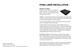
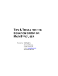
The Tea-serving Robot Developed in the Edo Period
The Karakuri Mechanical Doll
of the Flourishing Edo Period
*"Karakuri" means
the mechanism
that drives
a machine.
This automatic doll is restored according to the "Karakuri Zui": the
only existing illustrated manual written in the Edo period(1603∼
1867). It approaches a guest holding a cup of tea in its hands
and clears away the teacup when it becomes empty. This Karakuri
doll can be said to be one of the original forms of modern robots.
カラクリ人形改訂英語版印刷 06.11.13 1:10 PM ページ 3
CONTENTS
Contents and Cautions…………2
The World of Karakuri
Mechanical Dolls… … … … … 3
The Figure of the Finished
Mechanical Doll… … … … … 20
Let’s Do the Test Run! … … … 21
Parts in this Kit……………………4
Make Fine Adjustment to Each Part…22
Let’s Assemble the Cart!………6
Check the Move of the Doll……23
Make the Final Adjustment
Let’s Install the Escapement!…9
Let’s Assemble the Chest Unit! …11
Let’s Assemble the Motive
before your Performance… … … 24
Power Unit! … … … … … … … 14
How to Dress the Doll in Kimono…25
Mechanism of the Karakuri
Let’s Install the Other Parts!…19
Mechanical Doll… … … … … 26
The World of Karakuri Mechanical Dolls
The history of Karakuri ("Karakuri" means the mechanism that drives a
machine.) automatic dolls in Japan began in the early Edo period(1603~1867).
The tea-serving doll is the most typical one and it appears in the book
written by Ihara Saikaku, a very popular novelist in the Edo period. This
Karakuri doll kit is produced according to the “Karakuri Zui”, the only
existing manual of Karakuri mechanical dolls written in 1796 by
Hosokawa Hanzo, popularly
known as Karakuri Hanzo
who was an engineer of
Tosa domain. Karakuri
dolls can be said to be one
of the original foams of
CAUTION! ★Please read the following instructions before using this kit.
● Be careful of handling thin and pointed metal bars contained in this kit.
Improper use may cause injury to persons.
● Be careful of handling some metallic parts that are made thin and sharp
functionally. Improper use may cause injury to persons.
● Be careful not to swallow small parts to avoid suffocation.
● Be careful not to point your hands and eyes with the screwdriver in this kit to avoid
injury.
modern robots.
Please enjoy
the beauty of
Japanese
craftsmanship
of those days
by assembling
this kit.
● Be careful that your fingers are not caught in a machine while operation.
● Do not operate the doll on a road to avoid the risk of traffic accidents.
● Do not break up the mainspring. An inner spring may cause injury to persons.
★ Please read the assembly instructions and cautions in this booklet carefully before use.
Do not use the parts that are broken or deformed.
★ Please handle the doll with good care. The doll may be broken if it is treated roughly.
For example, do not shake it with its head down.
★ Be careful not to be scalded when the doll serves hot drinks.
★ The colors may fade out of Kimonos when it is exposed to the sun. Keep the doll with care.
★ Do not wash the Kimonos with whites. The colors may be washed off and stain whites.
● The plastic materials used in this kit
head (white) : styrene
body, tray, tweezers and other brown parts : styrene
arms, feet and other white parts : polyacetal
guards (transparent) : polyethylene terephthalate handle of the screwdriver : polystyrene
small bags (transparent) : polyethylene
*When you dispose the kit, follow the regulations of each local government.
2
3
カラクリ人形改訂英語版印刷 06.11.13 1:10 PM ページ 5
escape wheel
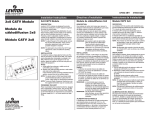
Parts in this Kit
tension spring (small)
neck (left)
neck (right)
neck joint
(upper)
looped string (small)
front wheel
tension spring (middle)
tension spring (large)
*For each size, two springs
are contained in this kit. One
is a spare.
looped string (middle)
escapement
bridge
looped string (large)
neck bridge
escapement
front wheel rubber
front wheel
connector
front wheel
bearing
left
arm
escapement
cock
front wheel bridge
upper chest
driving
wheel cover
left body
neck joint
(lower)
lower chest
right arm
driving wheel
auxiliary
wheel
bottom panel
arm shaft
*If the driving wheel cover is
stuck in the auxiliary wheel,
please separate each other.
auto-adjustment
pin
both sides
adhesive tape
head
lower
guard
reversal
stopper A
mainspring shaft
driving wheel
rubber
left foot
A Variety of Screws
upper
guard
rubber
band
right foot
A: 8 pieces of 3-by-8 mm
screws
right body
mainspring
adjuster
B: 3 pieces of 2.6-by-5 mm
screws with a collar
hakama
skirt
reversal stopper B
rotary wheel A
chanchanko vest
rotary wheel B
winding knob
kimono
top 1
kimono
top 2
tweezers
4
teacup
E: 8 pieces of 2-by-6 mm
screws
F: 4 pieces of 3-by-6 mm
screws
screwdriver
large wheel
C: 5 pieces of 2-by-5 mm
screws with a collar
D: 4 pieces of 2-by-10 mm
screws
tray
rotary plate
front chest
*For handy usage, put screws
on small trays separately.
5
カラクリ人形改訂英語版印刷 06.11.13 1:10 PM ページ 7
4
Let’s Assemble the Cart!
●Parts to be used
bottom panel
driving wheel
Fit the front wheel rubber
around the front wheel. Put the
wheel into the front wheel
bearing.
looped string
(large, middle, small)
5
Fasten the front wheel bearing
to the bottom panel with a screw
C.
front wheel bearing
screw C (2-by-5
mm with a collar)
Put it in until it snaps.
driving wheel
cover
tension spring
(large, middle, small)
driving
wheel
rubber
bottom panel
front wheel
rubber
front wheel
front wheel bridge
connector
auxiliary wheel right foot
front wheel
front wheel
rubber
1
front wheel
bearing
Screws to
be used
3 pieces of screw
C’s 2-by-5 mm
with a collar
left foot
a piece of screw E
2-by-6 mm
※ Select correct screws since all screws resemble in shape.
Insert each looped string into each tension spring.
Note: In this “Let’s make the
Pay attention to the combinations.
cart” section, only tension
spring (small) is used. At
tension spring (small)
looped string (small)
tension spring (middle)
tension spring (large)
looped string (middle)
looped string (large)
this time, however, prepare
all three tension springs by
inserting strings to avoid
mistakes, since the three
parts look alike and may be
mistaken. Keep these
springs back in the bags
when they are ready.
Insert the end of a looped string
into the other end with a knot.
Insert a string into
the hole at the tip of
a tension spring.
2
Pull and fasten it tight to the
spring as shown in the figure.
Insert the tension spring (small)
into the socket on the bottom
plate.(Put it in completely like
3
Fit the front wheel connector to the
projection of the bottom panel.
the figure below.)
front wheel
bearing
front wheel
connector
front wheel
6
Connect the front wheel bearing
and the front wheel connector
with the front wheel bridge and
fasten with screw C’s.
screw C (2by-5 mm
with a
collar)
fold line
bottom panel
6
bottom panel
Hang the string attached to the
tension spring (small) on the
hook of the front wheel connector
with tweezers.
※When you use the
tweezers it may turn
white at the pivot,
yet it is usable.
front wheel bridge
screw C (2by-5 mm
with a
collar)
front wheel
connector
◆Attach the end of
the front wheel
bridge with a fold ※However the front wheel bridge
line to the front
might twist reversely at the center,
it is no problem.
wheel bearing.
8
Move the front wheel connector
hook
◆Bend the tension
spring (small) with
your fingers until the
string reaches the
hook, then hang the
string on the hook.
tension spring (small)
Place the bottom panel with its
the front wheel turns right and
9
left smoothly.
◆Screw E is used for adjustment afterward.
back and forth and make sure
◆If the front wheel does not
move smoothly, loosen the
screw and make an adjustment.
tension
spring
(small)
◆Make sure the
direction of the
connector is like
this figure.
7
※At this point the front
wheel connector comes
off easily. Pay attention
not to lose the connector.
bottom panel
face down and turn the screw E
just a few times at this point.
screw E
(2-by-6 mm)
◆Please see
p.22 for the
※Be careful
not to mistake adjustment of
the hole.
screw E.
bottom panel
(backside)
7
カラクリ人形改訂英語版印刷 06.11.13 1:11 PM ページ 9
10
Put the driving wheel cover on
the driving wheel.
11
Fit the driving wheel rubber in
the groove between driving
Let’s Install the Escapement!
wheel and driving wheel cover.
driving wheel
cover
●Parts to be used
escapement
driving wheel
rubber
driving wheel
driving wheel
escape wheel
left body
Screws to
be used
◆Fit the projection of the driving wheel to the
holes of the driving wheel cover and snap in.
12
Attach the auxiliary wheel to
the shaft of the driving wheel.
auxiliary
wheel
driving wheel
◆The direction of
the auxiliary wheel
is like the figure.
escapement bridge
escapement cock
2 piece of screw
C’s, 2-by-5 mm
with a collar
3 pieces of screw
E’s, 2-by-6 mm
4 pieces of screw
F’s, 3-by-6 mm
※ Select right screws since all screws resemble in shape.
13
Install feet inside the driving
wheel and auxiliary wheel.
Set the escape wheel in the
1
socket of the left body.
(Be careful not to install right foot and left
foot inversely.)
right foot
escape wheel
◆Insert the point
of the shaft in the
hole at the bottom
left foot
2
Push the escapement bridge into
the left body.
◆Push the projections at the top and the bottom of
the escapement bridge into the holes of the left body.
At the same time, push the shaft of the escape wheel
into the center hole of the escapement.
left body
of the socket.
escape
wheel
left body
bottom panel
◆Push the shaft of driving
wheel in shaft bearings of the
bottom panel.
guide
guide
◆Cover the projections on the driving wheel and the
auxiliary wheel with U-shaped parts of feet.
Fit the feet with the guides on the bottom panel.
Now the cart is completed!
Caution! : This is not the hole
mentioned above.
3
Fasten the escapement
bridge to the left body
with screw E’s from the
backside.
You’ve finished
the cart. Keep it
as it is until you
escapement
bridge
screw E (2-by-6 mm)
◆ These three screw E’s
have to be fastened
firmly.
screw E (2-by-6 mm)
use it at p.18.
screw E (2-by-6 mm)
left body
8
9
カラクリ人形改訂英語版印刷 06.11.13 1:11 PM ページ 11
4
Attach four screw F's to the bottom parts of the escapement.
Let’s Assemble the Chest Unit!
pallet
◆ These four screw F’s
have to be fastened
firmly.
●Parts to be used
screw F’s (3by-6 mm )
neck
(right)
pallet
tension spring (middle)
screw F’s (3by-6 mm )
upper chest
neck
(left)
tension spring (large)
Note: Tension springs
(middle and large) are
going to be used. Strings
have already been put
through these springs at
the “Let’s assemble the
cart!” section.
front chest
neck joint (upper)
escapement
5
Place the escapement
on the escapement
left body
bridge in the
direction like
this figure.
escapement
Put the pallet in the
escapement.
6
Screws to
be used
Put the escapement
cock on the escapement
and fasten it with
screw C’s.
screw C’s
(2-by-5 mm
with a
collar)
escapement cock
left body
neck bridge
neck joint (lower)
lower chest
2 pieces of screw
B’s, 2.6-by-5 mm
with a collar
1 piece of screw
※ Select right screws carefully since all screws resemble in shape.
1
Put the neck joint (upper)
IMPORTANT Pay attention to the
between the neck parts (right
direction of the neck joint
and left) and fasten it with a
(upper).
flat part
screw E.
flat part
projection
screw E
(2-by-6 mm)
neck joint
(upper)
screw E
(2-by-6 mm)
escapement bridge
neck (left)
Now the left
body is
completed!
You’ve finished installing
the escapement to the left
body. Look at the figure to
make sure that the
escapement is correctly
attached.
10
The roll of the
escapement
The main components of the
escapement are two cylindrical
parts with pallets attached on
the upper part of the shaft.
The escapement controls the
speed of the rotation by
hanging the pallets on the
wheels. The heavier are the
sheet weights around the
bottom parts of the shaft, the
more slowly the wheel rotates,
and the lighter, the faster.
4 pieces of screw
E’s, 2-by-6 mm
D, 2-by-10 mm
2
neck (left)
Attach screw B’s on the chest (upper) as
the figure shows. Turn them a couple of
times and fasten them loose, so that a
projection
neck (right)
3
Hold the chest and the neck
as shown in the figure, and
fasten them with screw B’s.
small space remains between collars of
screws and the chest. Fit the projection
of the neck into the groove.
screw B’s, 2.6by-5 mm with
a collar
upper chest
flat part
neck
11
カラクリ人形改訂英語版印刷 06.11.13 1:11 PM ページ 13
4
Check if the neck and the neck
joint (upper) move back and
forth smoothly.
5
Put tension springs (large and
middle) into frames on the
chest (lower) to the end as
10
Put the hole of the neck bridge
on the projection of the neck
joint (upper).
11
shown in the figure.
front chest in the groove of the
lower chest.Turn the screw D for
adjustment just a couple of times.
tension spring
(middle)
Clatter!
Hold the bridge softly and fit the
neck joint (upper)
※Put in the upper
part of the front chest
first, then, fit the
lower part in the
groove below.
Side View
chest (lower)
<front side>
◆Be careful not to
take the large sheet
spring for middle,
because both springs
have the same width,
although their
lengths are different.
tension
spring
(large)
6
Turn over the lower chest and
put the neck joint (lower) on the
projection of the lower chest.
7
Fasten the upper chest and
the lower chest with screw E’s
paying attention to the
direction of each part.
neck joint (lower)
screw E (2-by-6 mm)
lower chest
<backside>
groove
lower
chest
12
neck bridge
front chest
◆See p.22 for the
adjustment of the
screw D.
Hang the string of the tension spring (large) on
the hook at the side of the neck with tweezers.
Side View
neck
hook
◆Screw enough so
that the parts will
not slip out of the
place.
upper
chest
◆Pay attention to the
direction. Attach the
joint in this direction
and angle as shown in
the figure.
screw E (2-by6 mm)
screw D (2-by10 mm)
neck bridge
◆Bend the tension spring (large) with your
fingers until the string reaches the hook, then
hang the string on the hook with tweezers.
Side View
lower
chest
◆ Pay attention to the direction.
8
Put the neck bridge in the hole
of the neck joint (lower).
9
Keep the neck bridge down.
Now the Chest Unit is Completed!
You’ve finished the
chest unit. Look at
Side View
neck bridge
the figure to make
sure if it is correctly
neck bridge
assembled.
Side View
◆Pay attention
to the direction.
neck joint (lower)
※Hold the part from the backside with
12
fingers so that you can see the hole.
neck joint
(lower)
13
カラクリ人形改訂英語版印刷 06.11.13 1:11 PM ページ 15
Let’s Assemble the Motive Power Unit!
●Parts to be used
mainspring shaft
arm shaft
adjuster
rotary wheel B
3
Attach the reversal stopper B and the rotary wheel B to the large wheel.
①Put the reversal stopper
B on the projection of the
large wheel.
②Fit the rotary wheel B
in the center hole of the
large wheel.
reversal
stopper B
reversal stopper B
③Make sure that the
rotary wheel B turns in
the only one direction
clattering.
rotary
wheel B
Clatt
er!
rotary plate
rubber band
reversal stopper A
rotary wheel A
right body
Screws to
be used
8 pieces of screw
A’s, 3-by-8 mm
large wheel
1 piece of screw B, 2.6by-5 mm with a collar
mainspring
1 piece of screw D,
2-by-10 mm
※ Select right screws since all screws resemble in shape.
1
Attach the adjuster to the rotary plate. Put the
adjuster on the projection and fasten with a screw B.
The adjuster can move left
and right to some extent
large wheel
4
Put the mainspring shaft through the rotary plate first, then though the
large wheel in the direction as shown in the figure.
by loosening the screw B.
screw B (2.6-by-5 mm with a collar)
adjuster
rotary plate
mainspring shaft
◆At this point, fasten
the adjuster temporarily
with a screw B. See p.22
for the adjustment of the
screw.
2
large wheel
Turn over the rotary plate and attach the reversal stopper A and rotary
wheel A in the right direction.
①Place the rotary plate with its
②Fit the rotary wheel A in
backside (without a screw) up
the center hole of the rotary
and put the reversal stopper A on
plate.
rotary
the projection.
reversal stopper A
wheel A
※Put it on to
rotary plate
the end.
③Make sure that the rotary
wheel A turns to only one
direction clattering. (The
mechanism a wheel can turn
only in one direction like
this, is called “ratchet
mechanism”.)
Cl
5
Put the rubber band into the
mainspring shaft to the end so
that the parts don’t come apart.
large wheel
rotary wheel B
rotary wheel A
rotary plate
rubber band
atter!
rubber band
14
rotary plate
◆ Side view is
like this figure.
mainspring shaft
15
カラクリ人形改訂英語版印刷 06.11.13 1:11 PM ページ 17
6
Attach the mainspring to the
right body in the direction like
the figure below.
◆ Fit the two small
projections of mainspring
in the holes of the right
body.
small
mainspring
projection
Fasten the mainspring to the
7
right body with screw A’s.
◆ These two
screw A’s have to
be fastened
firmly, not
temporarily.
10
Insert the mainspring shaft into the center hole of the mainspring, while
holding up the neck joint (lower) so that it isn’t in the way.
◆ Put your finger through
the front chest and push the
neck bridge to raise the neck
joint (lower).
push
mainspring
neck joint (lower)
screw A
(3-by-8 mm)
go up
mainspring
large
projection
right body
8
screw A
(3-by-8 mm)
small projection
Attach the chest unit finished
at p.13 to the right body.
9
Fasten the chest unit to the
right body with screw A’s.
11
Fasten a screw D for adjustment to the arm shaft loose. Then, put the arm
shaft through the front chest till the tip comes out from the hole of the right
body.
※ Screw just four or five times
to fasten loose.
chest unit
screw A
(3-by-8 mm)
screw A
(3-by-8 mm)
◆ Put four projections
of the chest unit in the
holes of the right body.
mainspring shaft
right body
◆ Fasten these
two screw A’s a
little bit loose
and leave a room
to screw firmly
as a finishing.
arm shaft
screw D
(2-by-10 mm)
◆ See p.22 for the
adjustment of the
screw.
◆ After the mainspring shaft was put in, the neck
joint (lower) goes between the rotary plate and the
large wheel as shown in the figure.
right body
16
17
カラクリ人形改訂英語版印刷 06.11.13 1:11 PM ページ 19
12
Attach the left body to the chest unit.
◆ Put four projections
of the chest unit in the
holes of the left body.
Let’s Install Other Parts!
◆ Fasten these two screw A’s
a little bit loose and leave a
room to screw firmly as a
finishing.
●Parts to be used
head
Screws to
be used
right arm
left arm
screw A
(3-by-8 mm)
tray
auto-adjustment pin
screw A
(3-by-8 mm)
1
Hang the string of the tension
spring (middle) on the hook of
the arm shaft.
◆ Thrust the tips
of the arm shaft
and the mainspring
shaft out of the holes
assembled above on the cart
you’ve finished on page 8.
14
arms to the arm shaft and fasten
with screw D’s.
screw D
(2-by-10 mm)
tension spring (middle)
13
Attach the right and the left
screw D (2-by-10 mm)
the hook, then hang
the string on the
hook with
tweezers.
left body
of the left body.
Place the body unit you
2
hook
◆ Bend the tension
spring (middle) with
your fingers until
the string reaches
2 pieces of
screw D’s
2-by-10 mm
Fasten the right body and
the left body with screw A’s
from the backside of the cart.
◆ Put six projections of the left body and the
right body in the holes of the cart firmly.
3
Install the auto-adjustment pin.
◆ Put the point of the pin in the hole of
the escapement bridge first, and then
snap it to fit in the groove between the
arm shaft and the lower chest.
◆ The projection of the mainspring comes to
the front.
left arm
right arm
4
Insert the head into the neck
and insert the both arms into
the tray. Now you’ve done!
head
ap!
Sn
bottom panel
<backside>
screw A
(3-by-8 mm)
screw A
(3-by-8 mm)
◆ Fasten these two screw A’s a little bit loose at
this point. Make sure that there is no distortion
all over, then fasten screw A’s (not only the two
screw A’s fastened now but also screw A’s
fastened loose at 9 and 12) again firmly.
18
tray
auto-adjustment pin
19
カラクリ人形改訂英語版印刷 06.11.13 1:11 PM ページ 21
Let’s Do the Test Run
The Finished Mechanical Doll
Check the action of each part
◆CHECK!◆
tension spring
before you dress the doll.
1
Set the doll on the flat place and
wind up the mainspring with the
winding knob.
2
When you put the teacup on
the tray, the doll starts
moving. First, it goes straight.
※Do not fill the cup with
tea during the test so that
◆CHECK!◆
escape wheel&
auto-adjustment pin
the tea might not be spilt.
◆CHECK!◆
driving wheel&
large wheel
(backside)
3
After the doll goes straight for a
5
After the turn, it goes straight.
while, it makes a bow. Then, take
the teacup and the doll stops.
4
Return the teacup on the tray
and the doll starts moving
again. Then, it makes a turn.
(backside)
◆CHECK!◆
bottom panel
(backside)
◆CHECK!◆
front wheel connector&
front wheel bridge
front wheel bridge
screw C
(2-by-5
mm with
a collar)
projection
front wheel connector
projection
6
When the doll gets back to
the starting point, take the
teacup and the doll stops.
*When you don’t use the doll for a long time*
1. Be sure to take off the teacup from the tray, otherwise the tension
spring might deteriorate and become useless.
2. Be sure to leave the mainspring unwound. Loosen it completely.
It might become out of order, if it is left wound for a long time.
20
21
カラクリ人形改訂英語版印刷 06.11.13 1:11 PM ページ 23
Make Fine Adjustments to each part
Before your performance in front of guests, test a couple of times and grasp how each part works, how
long the doll moves and how it turns. Then make fine adjustments to each action as follows if necessary.
1. The angle of the neck→Adjust
the screw at the chest.
2. The angle of the tray →Adjust the
screw at the arm shaft.
The screw at the front chest is to adjust
Adjust the angle of the tray so that it
the neck angle. Turn it clockwise or
becomes level when you put on the
counterclockwise to adjust.
teacup.
the screw for
adjustment
Remove
the head.
the screw for
adjustment
*Before you make
this adjustment,
unwind the
mainspring.
When you turn the screw clockwise,
the arms go up.
When you turn the screw counterclockwise, the doll looks upward.
When you turn the screw counterclockwise, the arms go down.
3. Course→Adjust the screw at
the bottom panel.
4. The angle of the turn→Move the
adjuster at the rotary plate.
Adjust the doll so that it goes
Loosen the screw before you move the
straightforward. (If you don’t make this
adjuster. Adjust the angle of the turn.
adjustment, the doll tends to go
Look at the consecutive action of the doll
rightward.) When the doll doesn’t go
and adjust so that it makes good turn.
adjuster
the screw for
adjustment
Loosen this
screw to move
the adjuster.
rotary plate
When you turn the screw
clockwise, the doll goes rightward.
When you turn the screw counterclockwise, the doll goes leftward.
22
If the doll moves as follows, you’ve made good adjustments. Check it now!
3
When you
return the
2
When you turn the screw clockwise,
the doll looks downward.
straight, adjust this screw.
Check the Move of the Doll
When you move the adjuster
rightward, the angle of the
turn becomes larger.
When you move the adjuster
leftward, the angle of the
turn becomes smaller.
When the doll makes
a bow, pick up the
teacup. Then, the
arms go up, the autoadjustment pin is
caught between the
cogs of the
escapement wheel
and the doll stops.
1
Wind up the
mainspring. Put
the teacup on the
tray. Then, the arm
goes down, the autoadjustment pin
becomes off and the
doll starts moving.
First, the doll goes
straightforward.
These are the three basic moves of the doll.
teacup on the
tray, the doll
starts again
and makes a
turn this time.
4
After making a
turn, the doll
goes straight.
Now the doll
repeats the
same move as
1 actually.
5
When the doll
comes back,
pick up the
teacup. Then,
the doll stops.
This is the end
of a series of
moves.
1. The doll starts moving when the teacup is put
on the tray and stops when the teacup is taken.
2. The doll goes straight about a fixed distance
(90 cm at the longest).
3. The doll turns after it makes a bow.
23
カラクリ人形改訂英語版印刷 06.11.13 1:11 PM ページ 25
Make the Final Adjustment Before your Performance
When you finish the adjustments on
p.22, make the final adjustment before
1
Wind up the mainspring.
●How to Dress the Doll
★Before you start dressing ★
Put on guards (upper and
guard (upper)
lower) beforehand so that
guard (lower)
adjustment is possible after the doll is
the dress is not caught in
dressed. In that case, pull the hakama
wheels.
◆ Pay attention
to the direction.
you show the doll to your guest.(This
up.)
● Adjust the distance between the
starting point and where the doll bows
in front of your guest.
1 Dress the kimono tops.
Parts to be used
1. Cut a both side adhesive
2. Put each arm through sleeves of the
tape into 10cm. Put it on the
inside of the back margin of
the kimono top 1 (the left
side when you face it).
kimono top 1 and the 2. Peel the thin
paper from the adhesive tape and paste
the both sides of kimono tops together at
the back.
hakama
skirt
Align the
collars of
both tops.
2
kimono
top 2
chanchanko
vest
When you wind up the mainspring, the adjuster at the rotary plate comes to
both side
adhesive tape
the position shown in the figure below. Turn the rotary plate clockwise and
change the position to suite the distance between you and the guest. (The
more you turn, the less the distance becomes. Take a look at the figure
below and adjust the distance.)
※ Be sure to turn the rotary
plate always clockwise.
When the adjuster is at this
position, the doll goes straight
about 45 cm.
When the mainspring is wound,
the adjuster comes to this position.
The doll goes straight about 90 cm
(the longest) if you set the doll in
motion in this condition.
2 Dress the hakama skirt.
1. Unfold the hakama skirt and put
through the doll from the bottom. Bring
the front laces back and tie them at the
back.(Tie the laces at the height as shown
in the figure below. Adjust the skirt so
that the insteps come out a little bit.)
the tray. →The tension spring (middle)
might not be working well. Knot the string
twice and make the loop smaller or change
the tension spring (middle) with a spare.
★The doll doesn’t go straight after the turn.
→The tension spring (small) might not be
working well. Knot the string twice and
make the loop smaller or change the tension
spring (small) with a spare.
2. Bring the back laces to the front and tie them at
the front. (Cover the back knot with the hakama skirt.
Make the back part higher and the front part lower.)
※ Check the collar, the nape, the neckline and the position
of the hakama skirt. If they are all right, cut the rest of the
adhesive tape and fasten the front with it.
◆Note: Keep the screw of the
adjuster as it is. (Do not loosen it
and change the position of the
adjuster itself.)
the back
part
higher
●If the doll doesn’t move successfully after all adjustments, check the following points.●
★The doll starts right after you wind up the
mainspring without putting the teacup on
24
kimono
top 1
★The doll bows from the beginning. →The
tension spring (large) might not be working
well. Knot the string twice and make the
loop smaller or change the tension spring
(large) with a spare.
★The doll doesn’t make a bow at all.→If the
doll is dressed already and if it is too tight
around the neck, the doll can’t bow. In this
case, loosen the Kimono a little so that the
doll can move the neck.
the front part lower
Finished!
3 Dress the chanchanko vest.
Take off the head. Turn the
vest upside down and put the
both arms through sleeve
holes as shown in the figure.
Dress the vest as it covers the
neck. Tie the laces. (If the
front knot comes out forward,
fasten with an adhesive tape.)
Put the head on again. Now
you’ve finished!
↑Take off the head
and dress the
chanchanko vest.
Note: If the front is
crossed too tight,
the doll can’t bow.
Check if the neck
can move back and
forth before you
fasten the front
with a tape.
↑Tie the
front laces.
↑Attach the tray. Be
careful that the front laces
do not touch the tray.
25
カラクリ人形改訂英語版印刷 06.11.13 1:11 PM ページ 27
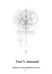
Mechanisms of the Karakuri Mechanical Doll
●The mechanism of a bow
What mechanisms make this doll move?
This karakuri doll is basically modeled after the mechanisms described in the
“Karakuri Zui”. The very best technologies of the Edo period(1603~1867) are applied
to the mechanisms of the doll.
●The mechanism of a start and a stop
What takes on the switching system for a start and a stop
is the auto-adjustment pin connected with the arms. (The
in the figure of the "Karakuri Zui") When you put the
teacup on the tray, the arms go down and the pin goes up.
This pin plays the role of the stopper for the cogwheel.
When the pin goes up, the stopper becomes off and the
cogwheel starts turning. When you take the teacup, the
arms go up and the stopper works and the cogwheel stops.
This doll makes a bow politely when it brings a
cup of tea to the guest. What a charming action
it is! The part that controls this action is the
rotary plate. When the projection catches the
part extended from the neck, the front of the
neck is pulled and the head goes down. When
the projection gets out of the place, the neck is
released and the head goes back to the former
position. Since the rotary plate also controls the
front wheel, the doll always makes a bow before
it makes a turn coordinately.
●The mechanism of adjusting the speed
What controls the speed is a cogwheel at the back
part called “gyojirin”. (See the picture.) Being
caught in the cogwheel, the two stoppers at the
escapement controls the rotation. The technology
used for the escapement of a
Japanese clock is applied to this
mechanism. The sheet weights
around the speed control bar have
made the finer speed control possible.
No.1 wheel
●The mechanism of going straight
When the mainspring loosens, it generates power.
This power first effects on the No.1 wheel. This
wheel has 80 cogs. The power is transmitted to the
No.2 wheel, and it has 12 cogs. Based on the
calculation, the No.2 wheel turns about 7 times
while No.1 wheel turns once. After 5 turns,
however, the projection at the rotary plate begins
to push the front wheel. The doll moves about 18
cm while the No.2 wheel turns once, so it goes
straight about 90 cm long before the projection
catches the front wheel (and the doll begins to
turn). For the mainspring, the “Karakuri Zui”
specifies that a whale fin should be used.
●The mechanism of a turn
What takes on a turn is the little wheel at the
bottom. The angle of the wheel decides the course of
the doll just like the front wheel of a tricycle
determines its route. The angle of the wheel changes
by being pushed by the rotary plate. The doll
continues to turn right while the wheel is pushed.
When the front wheel connector gets off the
projection, the wheel goes back to the former position
and the doll goes straight. You can control the angle
of the turn by adjusting the projection.
26
No.2 wheel
●The mechanism of the
shuffle walk
While the doll is moving, its feet move
back and forth. It looks as if the doll
conforms to the manners of the tea
ceremony and shuffles forward. This
unique walk style is realized by the
crank movement made by the pivots
controlling the move of each foot,
since their shafts are not aligned with
the center of the driving wheels. The
"Karakuri Zui" instructs that the left
pivot should be attached forward and
right pivot backward.
References:Tachikawa, Shoji, Yomigaeru Karakuri (The Revival of the Karakuri Mechanism): NTT Publishing Company.
27
Tachikawa, Shoji and coauthors, Zusetu Karakuri (The Illustrated Karakuri Mechanism): Kawade Syobo Shinsha Publishing Company.