1
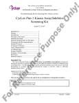
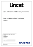
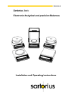
IS399 ECN3444
Dear Customer,
Thank you for purchasing this Lincat product.
This is just one of over 450 different items of catering equipment available
which is constantly being extended and improved. Details are available from
your local distributor or direct from us.
Used for the purposes for which it is intended, and with careful maintenance
as outlined in this User Guide, your Lincat product will give you years of
trouble free service.
IMPORTANT INFORMATION
Please read all of the safety and operating instructions carefully before using this
product. Please pay particular attention to all sections of this User Guide that carry
warning symbols and notices.
WARNING!
This is a Warning symbol. This symbol is used throughout the user guide
whenever there is a risk of personal injury. Ensure that these warnings are
read and understood at all times.
CAUTION!
This is a Caution symbol. This symbol is used throughout the user guide whenever
there is a risk damaging your Lincat product. Ensure that these warnings are read
and understood at all times.
NOTE:
This is a Note symbol. This symbol is used throughout the user guide to provide additional
information, hints and tips.
IS399 ECN3444
2
CONTENTS
Contents
Page
Customer Information……………………………………………………….
Warnings and Precautions…………………………………………………
Technical Data………………………………………………………………..
Commissioning……………………………………………………………….
User……………………………………………………………………………..
Servicing ………………………………………………………………………
Component Replacement ………………………………………….………
Spare Parts List………………………………………………………………
Fault Finding………………………………………………………………….
Circuit Diagrams……………………………………………………………..
Service Information…………………………………………….……………
2
3
4
5-6
7-11
12
12
13
13
14-15
16
WARNINGS AND PRECAUTIONS
It is mandatory that all appliances are installed, commissioned and serviced by a qualified
and competent person as defined by the regulations in force in the country of installation.
Failure to comply will invalidate the warranty.
WARNING!
This appliance must be installed by a competent installation engineer in accordance with the
installation instructions, and should conform to the following requirements:
It is recommended that this appliance is sited under an extraction canopy for the removal of
steam
After operation, some parts of the appliance will remain hot for a period of time. Please take
care to avoid accidental burns.
CAUTION!
All equipment must be earthed to prevent shock.
Parts which have been protected by the manufacturer or his agent must not be adjusted by
the installer or user.
IS399 ECN3444
3
TECHNICAL DATA
Description
Product Code
Overall height (mm)
Height to hob (mm)
Width (mm)
Depth, excluding handles (mm)
Tank dimensions - w x d (mm)
Legs adjustable within range (mm)
Weight (Kg)
Water capacity (litres)
Drain valve diameter (mm)
Electricity supply requirements
400 Wide
OE7701
1050
900
400
737
300 x 270
135 to 190
51Kg
24
25
3N~
600 Wide
OE7702
1050
900
600
737
500 x 270
135 to 190
65Kg
42
25
3N~
Three phase supply
Electricity supply requirements
26 amps
1N~
39 amps
1N~
Single phase supply
Power rating (kW)
26 amps
6
39 amps
9
IS399 ECN3444
4
COMMISSIONING
PREPARATION
Remove all packaging and protective coatings prior to installation.
SITING
The installer must ensure that all local regulations are met.
• The appliance must be installed on a level floor in a suitable position that is well lit, and
positioned so as to prevent accidental touching.
• On units supplied with legs, the height and level can be adjusted using the spanner provided.
• The unit should NOT be positioned next to any unit that has an exposed flame, such as a gas
range or chargrill.
• Partitions, walls, kitchen furniture and other materials less than 100 mm from the appliance
should be made from non-combustible material.
• Ensure there is a free flow of air and adequate ventilation around the appliance, and that no
vents are blocked.
• It is recommended that the appliance is sited under a canopy for the removal of steam.
ELECTRICAL SUPPLY AND CONNECTION
This appliance must be connected to the electricity supply by a qualified electrician, in
accordance with relevant regulations.
•
•
•
•
This appliance should be connected to mains electricity via a suitable isolating switch,
which should have at least a 3mm contact separation on all poles.
The isolator should be easily accessible in the event of an emergency.
Check that the power supply and the supply cable to be used is compatible with the rating of
the unit.
Remove the rear panel to gain access for connections.
WATER SUPPLY & WASTE
•
This appliance should be connected to mains water supply via the rear of the unit.
• The waste pipe (where fitted) of the unit should be connected to main drain via a Tun- Dish.
OPERATIONAL CHECK
•
•
•
•
•
Ensure that the water drain taps are closed.
Clean the tanks thoroughly with a warm mild detergent solution.
Rinse the tanks, drain pipes and taps, and then dry thoroughly.
Close the drain taps.
Fill the tank with water reach max level mark on rear wall of tank.
The appliance is fitted with a pressure switch and for the appliance to operate the tank must
be filled to the maximum level
IS399 ECN3444
5
Tank Capacities
Model No.
Capacity
OE7701
24 Litres
OE7702
42 Litres
•
•
•
•
With the control knob in the off position, switch the unit on at the isolator.
The green neon will light.
Turn the energy regulator control knob anti-clockwise to the required temperature.
The adjacent amber neon will light, indicating that the heating elements are energised.
Green Power On Indicator
Orange Element On Indicator
Mains Water Supply
Control/Tap
Temperature Control
Knob
OPERATIONAL CHECK
Although all Lincat units are functionally checked during manufacture, commissioning must
include a functional check of all controls.
Set the energy regulator to maximum and allow the water to heat up.
USER INSTRUCTION
Ensure that the person responsible understands how to safely operate, clean and shut down this
appliance and is made aware of the position of the isolating switch.
Note: This manual must be kept in a safe and accessible place for future reference.
IS399 ECN3444
6
USER INSTRUCTION
FILLING THE TANK
•
Check that the drain tap is closed in the safe locked position (see “Cleaning the tanks”).
•
Fill the tank of the appliance to the level mark on the rear tank wall by turning the mains
water supply tap on the control panel. Water will be dispersed from the inlet on the rear wall
of the tank.
If the mains water control valve is accidentally left open. There is an overflow trough in
front of the main tank, which is connected to the main drain.
•
Warning! Do not pour water onto hot elements, as this will damage the appliance.
WATER INLET
AMBER ELEMENT
ON INDICATOR
GREEN POWER
ON INDICATOR
WATER LEVEL
MARK
MAINS WATER
CONTROL VALVE/TAP
TANK THERMOSTAT
CONTROL
OPERATION
Always check that the tank is filled to the upper level before switching on the appliance.
•
•
•
•
•
Fit basket drainer locating onto pins in side of tank.
Position basket support in the bottom of the tank ensuring large cut-outs line up with
element positions.
Turn on the power supply at the isolating switch.
The green neon will light indicating that mains power is on, and amber neons will light
indicating that the heating elements are energised.
Rotate the control knob to the desired temperature setting.
IS399 ECN3444
7
•
•
•
When the temperature reaches the selected set point, the element will cycle on and off to
maintain the set temperature. Note: There is a range of 6 cycles on the control knob & a
constant power position beyond the ‘6’ setting.
Submerge baskets of pasta (positioning onto basket support) and cook as per manufacturers
instructions.
During cooking of pasta, starch may be scooped from the surface of water & poured into the
overflow/starch removal trough in front of the tank.
BASKET SUPPORT
GASTRONORM PAN
SUPPORT BAR
BASKET DRAINER
OVERFLOW COVER
•
•
•
For bains marie operation fit gastronorm
pan support (OE7702 Only) slotting into overflow cover.
Position gastronorm pans into top of tank, cover produce with gastronorm lids.
For steaming operation use perforated gastronorm pans and lids.
Should the water fail to heat when its neon is illuminated and the control knob is set to a heating
position, the high temperature cut-out may require re-setting. The cut-outs are located underneath
the control panel, accessed through the door.
Press the exposed button to reset the cut-out.
Should the appliance still fail to operate, consult a qualified electrical Engineer.
SUTTING DOWN THE APPLIANCE
To turn the appliance off completely, rotate the control knobs clockwise to the OFF position.
Warning: After operation, some parts of the appliance will remain hot for a period of
time. Please take care to avoid accidental burns.
Note: If the water level falls below the basket plate the pressure switch will operate closing power
to the elements. In the event of the unit completely boiling dry the element protector will operate
shutting down the appliance.
IS399 ECN3444
8
RESETTING THE LIMIT THERMOSTAT
•
•
•
•
Isolate the unit from the electrical supply.
Leave the unit for at least 20 minutes to cool before refilling to the indicated level with fresh
water.
Reset the limit thermostat by manually depressing the button (refer to the drawing below for
location).
Reconnect the unit to the electrical supply and operate as normal.
Right element, high temperature
limit stat, reset button.
Left element, high temperature
limit stat, reset button.
Central element, high temperature
limit stat, reset button
The above diagram shows reset button for OE7702. The OE7701 has only two reset buttons
for front and rear elements.
CLEANING
Before carrying out any cleaning of your unit, isolate the appliance from the power supply.
Allow the appliance to cool.
After use, clean the unit down with a warm detergent solution.
Do not use abrasive cleaners or any containing chlorine on stainless steel surfaces.
Do not use a water jet or a steam cleaner to clean the appliance.
IS399 ECN3444
9
SCALE
The formation of scale within a hot water system is common and if left unchecked may cause
problems to the functioning of the appliance. In hard water areas scale formation builds up quicker
than in softer water areas therefore checks on scale formation need to be more frequent. It is
advisable, in order to prevent injury, the appliance be isolated and allowed to cool before inspecting
for scale deposits within the tank.
DE-SCALING THE APPLIANCE
It is recommended that the appliance be de-scaled regularly using an approved de-scaling
compound. Excessive scale deposits may become difficult to remove with some de-scaling
products.
Do not use hydrochloric acid based de-scaling compounds on stainless steel.
•
•
•
•
•
•
To de-scale the appliance, isolate the appliance from the electricity supply.
Fill with water to the indicated level.
Turn on the electricity supply and heat the water to boiling then turn the thermostat off.
Add the de-scaling compound a little at a time, allow the frothing to subside then set the unit on
full. Some de-scaling compounds may cause hot water to erupt. It is advisable to follow the
instructions of the manufacturers.
Allow the appliance to heat for up to 30 minutes, then allow the water to cool.
In the case of severe scale deposits it may be necessary to repeat the de-scaling process.
On completion of successful de-scaling isolate from the supply, evacuate the tank via the drain tap
then rinse with clean water.
DRAINING THE WATER
•
•
•
•
•
Turn the unit off and isolate from the power supply.
Allow the water to cool to a maximum of 55°C.
Open the tap and allow the water to drain.
Open the water control valve to allow you to swirl water around the tank to assist rinsing debris
through the tank.
Close the tap to the safe locked position (see diagram below).
CLEANING THE TANKS
Food debris can be a health risk, ensure that food debris is cleaned from the unit after use.
•
Remove any debris from the bottom of the tank.
•
Wash the tanks, top surface of the body, basket drainer, overflow cover, basket support and
pan support with a warm detergent solution.
•
Rinse out the tank flushing any traces of detergent into the drain.
•
Close the drain taps into the safe locked position (see “Draining the water”).
•
Replace the basket drainer, overflow cover, batter plate and pan support.
•
Refill the tank with fresh water.
IS399 ECN3444
10
USING THE DRAIN TAP
DRAIN TAP
Depress
Align squares,
press to engage,
turn to open and close.
Turn to Open
Turn to Open
BASKET LOADS
Overloading the basket reduces the appliance output of cooked product and will result in uneven
cooking. It also increases the possibility of surge boiling (the water may suddenly boil over when
the basket is placed into the tank).
IS399 ECN3444
11
SERVICING
ROUTINE SERVICE
We recommend that all servicing, other than routine cleaning, be carried out by our authorised
service agents.
• Carry out a general check on the installation paying particular attention to the following:Is the unit installed with the correct rating of cable.
Is it connected to the supply via a suitable isolating switch.
• Check all components for correct operation and replace where necessary.
• Check the operation of the high temperature limit thermostats. The reset buttons are located
inside the unit, underneath the tank, see diagram.
• Check the operation of the high temperature limit thermostats. The reset buttons are located
inside the unit, underneath the tank, see above diagram.
COMPONENT REPLACEMENT
Warning: Disconnect all power supplies from the mains before proceeding.
Energy Regulator
•
•
•
•
Remove the control knob taking care not to lose the knob-retaining clip.
Remove the control panel by removing screws below panel and dropping panel down.
Remove wires from energy regulator & remove Two mounting screws.
Reassemble in reverse order.
Contactor
• Remove the rear cover.
• Remove the connections to the contactor.
• Remove the contactor from the frame.
• Reassemble in reverse order.
Safety Thermostat
• Remove front & rear element covers (inside unit).
• Remove thermostat mounting nut from relevant thermostat.
• Remove thermostat phial from element by sliding out of sleeve.
• Reassemble in reverse order.
Heating Element
• Remove the front & rear element covers (inside unit).
• Remove the safety thermostat as above.
• Remove element-mounting nuts (6 off) releasing element-mounting flange.
• Remove element & sealing gasket by lifting out of tank.
• Reassemble in reverse order
Important! When tightening element-mounting nuts ensure that they are tightened to a torque figure
of 1N/m. Over tightened the element gasket may not provide a watertight seal.
IS399 ECN3444
12
SPARE PARTS LIST
Part number
BA102
BA109
BA110
BA104
CO111
CO166
CO167
CO168
EL208
EN10
HA77
HA78
H157
HI60
HO107
KN233
LE37
NE39
NE40
PS05
SP56
TA101A
TE45
Description
Large basket
1/2 basket
1/3 basket
1/6 basket
Contactor
Swirl inlet fitting
½” Stop valve
Compact tee inlet
Element 3Kw
Energy Regulator
Door handle
Lid handle
Top/bottom door hinge
Bottom door hinge
Hose flexi braided
Control knob
Adjustable 150mm leg
Green neon
Amber neon
Pressure switch
Leg spanner
Drain tap
External terminal block
OE7701
X
X (2 off)
X (6 off)
X
X
X
X
X (2 off)
X
X
X
X
X
X
X
X
X
X
X
X
X
X
FAULT FINDING
APPLIANCE WILL NOT HEAT
Is the green neon
illuminated on the front
fascia?
no
Check the mains
isolator and fuse
no
Turn on the
energy regulator
no
Check safety
thermostat re-sets
no
Check the
contactor
yes
Is the energy
regulator turned on?
yes
Is the amber
neon lit?
yes
Is the contactor
operating?
yes
Check the
element
IS399 ECN3444
13
OE7702
X
X (3 off)
X (9 off)
X
X
X
X
X (2 off)
X
X
X
X
X
X
X
X
X
X
X
X
X
X
CIRCUIT DIAGRAMS
OE7701
PRESSURE SWITCH
PS05
Sleeve wires 9, 10 & 18 in
10mm sheathing, 800mm long.
Mark boots at each end with
wire number
TERMINAL BOX
TE45
LIMIT 'STAT
FRONT ELEMENT
GREEN
NEON
AMBER
NEON
LIMIT 'STAT
REAR ELEMENT
FRONT ELEMENT
EL208
ENERGY
REGULATOR
EN10
REAR ELEMENT
EL208
CONTACTOR
CO111
Sleeve wires 2 & 6 in
10mm sheathing, 600mm long.
Mark boots at each end with
wire number
Note: Wire 12 from the contactor to the pressure switch is wired to the Normally Open terminal.
Terminal numbers may vary.
CIRCUIT LEGEND
CO111
Contactor
EL208
Element
EN10
Energy Regulator
TH68
Over temp thermostat
NE39
Green neon
NE40
Orange neon
PS05
Pressure switch
TE45
Terminal block
IS399 ECN3444
14
OE7702
PRESSURE SWITCH
PS05
Sleeve wires 9, 10 and 24 in 10mm sheathing,
850mm long. Mark boots at each end with
wire number
LIMIT 'STAT
LEFT ELEMENT
GREEN
NEON
LIMIT 'STAT
CENTRE ELEMENT
AMBER
NEON
LIMIT 'STAT
RIGHT ELEMENT
ENERGY
REGULATOR
EN10
Sleeve wires 2, 6 and 14
in 10mm sheathing, 600mm long.
Mark boots at each end
with wire number
Note: Wire 12 from the contactor to the pressure switch is wired to the Normally Open terminal.
Terminal numbers may vary.
CIRCUIT LEGEND
CO111
Contactor
EL208
Element
EN10
Energy Regulator
TH68
Over temp thermostat
NE39
Green neon
NE40
Orange neon
PS05
Pressure switch
TE45
Terminal block
IS399 ECN3444
15
SERVICE INFORMATION
Catering equipment should be routinely serviced to ensure a long and trouble free life.
With this in mind it is recommended that appliances are serviced every six months by a competent
engineer.
For help regarding the installation, maintenance and use of your Lincat equipment, please call:-
LINCAT SERVICE HELP DESK
01522 875520
AUTHORISED SERVICE AGENTS
We recommend that all servicing other than routine cleaning be carried out by our authorised
service agents and will accept no responsibility for work carried out by other persons. Note that for
safe and efficient operation, appliances need regular servicing.
Please quote both the model and serial numbers from the data plate attached to the unit. Give brief
details of the service requirement.
If possible please quote the product code of the part you require.
Lincat reserve the right to carry out any work under warranty during normal working hours, i.e.
Monday to Friday, 8.30 a.m. - 5.00 p.m.
CONDITIONS OF GUARANTEE
The guarantee does not cover:-
•
•
•
Accidental breakage or damage
Operational misuse, wear and tear from normal usage, incorrect adjustment, or neglect.
Incorrect installation, maintenance, modification or unauthorised service work.
IS399 ECN3444
16