1
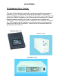
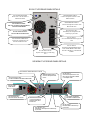
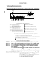
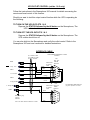
OWNER'S
GUIDE
ADDENDUM
UNINTERRUPTIBLE POWER SYSTEM
FOR MODELS:
SG1K-2T & SG1KRM-2T
SENSAPHONE 1104
FALCON® ELECTRIC
5116 Azusa Canyon Road
Irwindale, CA 91706
Tel. 626-962-7770
Fax. 626 962-7720
WWW.FALCONUPS.COM
800.842.6940
The information contained herein is the property of FALCON® ELECTRIC, is proprietary, confidential, and
not to be disclosed, disseminated or used except for the purpose provided by FALCON® Electric, Inc.
OM48204
7/03
IMPORTANT SAFETY INSTRUCTIONS
SAVE THESE INSTRUCTIONS
This manual contains important instructions which must be followed during the
installation, operation and maintenance of this device and it’s batteries. Please read
all instructions before operating this equipment and save this manual for future
reference.
CAUTION
All of the models presented herein are designed for installation and use in a
controlled environment free of contamination.
CAUTION
This device utilizes voltage that may be hazardous. Do not attempt to disassemble .
This unit contains no user replaceable parts. Refer all servicing to Falcon Electric,
Inc.
CAUTION
This device is not intended to be used in conjunction with life support or operating
room equipment.
CAUTION
Always unplug this device prior to cleaning and never apply liquid or spray detergent on the UPS.
CAUTION
When replacing the UPS batteries, use the same number and type of batteries (6
pieces of “D” Cell type batteries). Refer to the Sensaphone users manual for
details.
CHAPTER 1
SG Sensaphone Option- Overview
This User’s Guide Addendum is provided as preliminary installation and interfacing
instructions for your SG Series UPS incorporating a Sensaphone 1104 Remote
Telephone Management System. This manual is to be used in conjunction with the SG
Series User’s Manual, Sensaphone User’s Manual and the Sensaphone X10 Manual.
Read this handbook carefully in the order it is presented prior to installing and
operating your units. This will save you time and effort in your installation and application. The illustrations will also familiarize you with the equipment operating and programming modes as well as indications. Always operate this equipment within the
guidelines and specifications.
SENSAPHONE 1104
SG1K-2T UPS
SG1KRM-2T UPS
CHAPTER 2
Installation
Inspecting the Equipment
If any FALCON ® equipment has been damaged during shipment, keep
the shipping cartons and packing materials for the carrier and file a
claim for shipping damage. If you discover damage after acceptance,
file a claim for concealed damage.
To file a claim for shipping damage or concealed damage: 1) File with
the carrier within 15 days of receipt of the equipment; 2) Send a copy
of the damage claim within 15 days to the Falcon® Service Department.
UPS & Sensaphone 1104 Setup
1.
Verify that the following is included in the UPS shipping carton:
UPS, Input line cord, RS-232 software, Owner's Guide.
2.
Verify that the UPS unit is configured for the proper input/output
voltage. This information is stated on the nameplate label located on
the rear panel of the unit.
3.
Verify that the following is included in the Sensaphone shipping carton:
Sensaphone 1104 with connected UPS interface cable, Power Supply,
IEC320 to NEMA 5-15R adapter cable, User’s Manual and X10
Manual.
4.
Install the six “D” cell batteries into the Sensaphone unit. Refer to the
Sensaphone user’s manual for details.
4.
Select a suitable location for the UPS and Sensaphone unit, near
enough to the computer or equipment to be protected and monitored to
allow connection of the equipment power plug(s) to the receptacles
located on the rear panel of the UPS.
5.
DO NOT BLOCK UPS AIR VENTS. THE UPS MUST NOT BE
INSTALLED IN AN ENCLOSED AREA.
6.
Refer to the SG UPS Rear Panel Detail on the next page for the
following steps.
a.
Connect the Sensaphone input power to UPS outlet 4
using the supplied IEC320 to NEMA 5-15P adapter
cable.
b.
Connect the DB-9 MALE connector on the Sensaphone
interface cable to the Sensaphone A Port on the UPS rear
panel.
c.
Connect the DB-9 FEMALE connector on the
Sensaphone interface cable to the Sensaphone B Port on
the UPS rear panel.
SG1K-2T UPS REAR PANEL DETAILS
SG UPS DIP SWITCHES
Please refer to the SG Owner’s
Manual for details
SENSAPHONE PORT A
Connect Sensaphone interface cable
DB-9 male here
SENSAPHONE PORT B
Connect Sensaphone interface cable
DB-9 female here
SG UPS RS-232 PORT
DO NOT CONNECT SENSAPHONE
CONNECTORS HERE
IEC OUTLET 1 & 2
Switched by the Sensaphone and
backed up by the UPS
SG UPS COOLING FAN
DO NOT BLOCK AIR FLOW
IEC OUTLET 3
Not switchable and backed up by the
UPS
SG UPS LINE CORD INLET
Connect the supplied line cord
IEC320 end into the inlet.
SG UPS INPUT FUSE
Replace with same type and rating
fuse
IEC OUTLET 4
CONNECT SENSAPHONE INPUT
LINE CORD HERE USING THE
IEC320 to NEMA 5-15 ADAPTOR
CABLE.
SG1KRM-2T UPS REAR PANEL DETAILS
SG UPS DIP SWITCHES refer to manual
SENSAPHONE PORT A
Connect Sensaphone DB9 here
SG UPS RS-232 PORT
DO NOT CONNECT SENSAPHONE HERE
IEC OUTLET 4
Connect Sensaphone line cord
here using thr IEC320 to NEMA
5-15 adaptor cable
SG UPS LINE
CORD INLET
SG COOLING FAN
DO NOT BLOCK AIR FLOW
SENSAPHONE PORT B
Connect Sensaphone
interface cable, DB -9
female here
IEC OUTLET 1 & 2
Switched by Sensaphone and backed up
by the UPS
OPTIONAL EXTERNAL
BATTERY CONNECTOR
IEC OUTLET 3
Not switchable and backed up
by the UPS
d.
e.
f.
g.
h.
I.
j.
Connect the UPS input power cord to the UPS inlet
located on the UPS rear panel.
Verify the UPS output voltage Dip Switch setting match
your local utility voltage. Refer to the SG Owner’s Manual
for details.
Connect the UPS input plug to a nearby grounded
receptacle. NEVER USE AN EXTENSION CORD.
Connect the input power plugs for the equipment you want
to switch on and off to the UPS outlets 1 & 2 only. These
outlets are battery backed up.
Connect the input power plugs for the equipment you want
on all of the time to the non-switched UPS outlet 3. This
outlet is battery backed up.
UPS OUTLET 4 (BOTTOM OUTLET for SG1K-2T),
(OUTLET TO THE RIGHT FOR SG1KRM-2T) IS
RESERVED FOR CONNECTING THE SENSAPHONE
INPUT PLUG. THE SENSAPHONE INPUT PLUG MUST
BE CONNECTED TO THIS OUTLET.
READ THE SENSAPHONE OWNER’S AND X10
MANUALS BEFORE GOING ANY FURTHER.
CHAPTER 3
Preliminary Operating Instruction
SENSAPHONE CABLE CONNECTIONS & ASSOCIATED ALERT CONDITIONS
TEMPERATURE
SENSOR
5
Not
GND5 Used
SENSAPHONE REAR PANEL
ON
GND1
1
GND2
2
GND3
3
C
OFF
GND4 4
UPS & INTERFACE CABLE CONNECTIONS
GND1 Temperature Sensor Return
"Temperature Alert Condition 1"
1. ---- Temperature Sensor Signal
GND2 Utility Loss Return (orange wire)
"Alert Condition 2" (Utility Loss to UPS)
2. ---- Utility Loss Signal (brown wire)
GND3 On Battery Return (blue wire)
"Alert Condition 3" (UPS on at low battery)
3 ---- On Battery Signal (white wire)
GND4 Alarm/On bypass Return (green wire)
4 ---- Alarm/On bypass Signal (yellow wire)
GND5 UPS Output Control Return (gray wire)
5 ---- UPS Output Control Signal (violet wire)
"Alert Condition 4" (UPS in alarm or bypass)
Turns UPS outlets 1 & 2 on & off
Note: UPS outlets 1& 2 are controllable by the Sensaphone and backed up by the UPS.
UPS outlet 3 is on continuously and backed up by the UPS.
UPS outlet 4 is on continuously and backed up by the UPS. CONNECT SENSAPHONE
INPUT POWER PLUG TO THIS OUTLET
"Loss of Sensaphone Input Power Alert Condition" (UPS lost it's output)
UPS & SENSAPHONE ALERTS
ALERT 1
Room temperature (sensor located on the Sensaphone rear panel)
ALERT 2
Loss of utility voltage sensed at the UPS input. UPS in battery mode.
ALERT 3
UPS at low battery, approximately one minute of backup remaining.
ALERT 4
UPS is in bypass as a normal part of the UPS startup. Ignore and
reset the alarm.
OR
UPS has been manually placed in bypass using the front panel button.
OR
UPS is in an alarm condition. Refer to the SG user’s manual for alarm
details.
SENSAPHONE POWER ALERT The Sensaphone has lost input power. The UPS
has lost its output due to:
a. A sustained power outage and UPS shutdown
b. The UPS was manually turned off.
c. The UPS failed and lost output
UPS OUTLET CONTROL (outlets 1 & 2 only)
Follow the instructions in the Sensaphone X10 manual for details concerning the
remote and local control of this function.
Should you want to test this output control function while the UPS is operating do
the following:
TO TURN ON THE UPS OUTLETS 1 & 2
Depress the STATUS followed by the #6 button on the Sensaphone, The
UPS outlets should turn on.
TO TURN OFF THE UPS OUTLETS 1 & 2
Depress the STATUS followed by the #3 button on the Sensaphone. The
UPS outlets should turn off.
You can also dial into the Sensaphone and verify the outlet control. Refer to the
Sensaphone X10 and user’s manual for detailed instructions.
INTERFACE CABLE
SENSAPHONE INTERFACE CABLE
CA080338
12 Conductor Cable
Type CMR or CL2R
26 Awg, stranded
GND2
2 -Uty. Loss
White
Shrink Tube
in separate
cable
CN1
Rear View
DB-9M
PE56524
1
Blue
GND3
9
Brown
3 - Low Batt.
Orange
Yellow
GND4
4 - Bypass/Alm
5
6
Green
CN2
Rear View
Shrink Tube
DB-9F
in separate
PE56501
cable
5 - Output SD
GND5
Violet
5
Red #6 Ring Lug
6 places
PE57507
Gray
Note: Cut off all unused conductors in cable
1
6
9
Use DB-9 Back Shell PE655365
(2) places (mouser 152-1309
CHAPTER 4
Technical Support
Your FALCON ® Electric SG Series UPS is backed by one of the finest customer
service teams assembled. Write, Call, Fax or Email should you require
technical assistance or service.
For Sensaphone 1104 technical support or repair issues please contact the
manufacturer directly. Technical support contact information is referenced in the
Sensaphone User’s Manual.
FALCON ELECTRIC, INC.
5116 Azusa Canyon Road
Irwindale, CA. 91706
Voice 626.962.7770
Fax 626.962.7720
Service 800.842.6940
Email: [email protected]
WWW.FALCONUPS.COM
Should service be desired, you must first obtain a Return Material Authorization
number (RMA) and return shipping instructions from our customer service
department. Please have your UPS model, serial numbers and date of
purchase on hand prior to the call. This information is located on the
identification label on the rear panel of the unit. This information is essential in
retrieving your unit's historical records.
The RMA number issued must appear on the outside of the shipping carton.
The original shipping container must be used when returning any SG
Series product. Falcon ® Electric will not assume any responsibility for shipping
damage. In the event of shipping damage you will be charged for repairs due
to the damage.
All units must be returned prepaid. The address and shipping instructions will
be given to you at the time the RMA is issued.
7.
Requesting Technical Information or Support.
You may request technical information or support by Email or telephone.
Please send your technical or support questions by Email to:
[email protected]
You may contact a FALCON support engineer directly by calling the FALCON
support line between 9:00 am and 4:00 pm PST.
626.962.7770
8.
FALCON Web Support
Product data sheets, specification and owner’s guides are available in Adobe
.PDF format on our corporate website.
WWW.FALCONUPS.COM