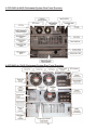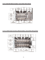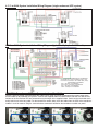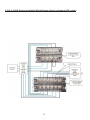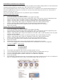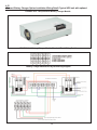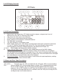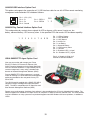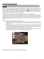
1
OWNER'S
OPERATING
MANUAL
FN SeriesTM Rackmount UPS Plus®
Parallel or N+1 Redundant 3kVA to 24kVA
Hardwire models with a 208-240Vac Input and 120Vac, 208Vac & 240Vac Outputs
Uninterruptible Power Supply Models:
FN3KRM-2, -2TX & -2TXI
FN4KRM-2, -2TX & -2TXI
FN5KRM-2, -2TX, & -2TXI
FN6KRM-2, -2TX & -2TXI
FN8KRM-2, -2TX & -2TXI
FN10KRM-2, -2TX & -2TXI
FALCON® Electric, Inc., 5116 Azusa Canyon Rd., Irwindale, California 91706, (626) 962-7770, Fax (626) 962-7720, Email: [email protected]
2011 Falcon® Electric Inc. All rights reserved.
All other brand names and trademarks are the property of their respective owners.
The information stated in this document is subject to change without notice. 2011-11-03
Falcon®, Falcon® Electric, FN and UPS Plus logos are registered trademarks of Falcon Electric, Inc.
TABLE OF CONTENTS
FN Rackmount Series Parallelable and N+1 Redundant UPS Features..
FN -2TX Double-Conversion On-line UPS Block Diagram.
.
Important Safety Instructions
(READ FIRST)
.
.
Chapter 1. Introduction
1.1 Manual Overview.
.
.
.
1.2 Brief FN Overview.
.
.
.
Chapter 2. FN UPS Circuit Descriptions
Galvanically Isolated Output.
.
.
Input & Power Factor Correction
.
.
Power Factor Correction.
.
.
DC/DC Converter. .
.
.
.
DC/AC Inverter
.
.
.
Battery Packs
.
.
.
.
Internal Battery Charger
.
.
.
Static Bypass Function.
.
.
.
Automatic Bypass Transfers
.
.
Output FIlter
.
.
.
.
Chapter 3. Unpacking the UPS and Battery Bank
3.1 Unpacking Instructions
.
.
.
Chapter 4. Pre-installation Details
4.1 Floor Loading Requirements
.
.
.
4.2 UPS Input Power Requirements. .
.
.
4.3 UPS Input/Output Requirements .
.
.
4.4 UPS Output Rating Details
.
.
.
4.5 FN 3-6kVA System Rear Panel Overview
.
.
4.6 FN8-10kVA System Rear Panel Overview .
.
4.7 3-6kVA Hardwire Terminal Block Wiring Details
.
4.8 UPS Rear Panel Details .
.
.
.
4.11 3-6kVA System Installation Wiring Diagram, Single UPS Unit
4.12 3-6kVA System Installation Wiring Diagram, Multiple Parallel
4.13 UPS & Transformer Module Communications Bus Cabling..
4.14 8-10kVA System Installation Wiring Diagram, Typical
4.15 External Battery Charger Option Installation
.
.
.
.
.
.
.
.
.
.
3
3
4
.
.
.
.
.
.
5
5
.
.
.
.
.
.
.
.
.
.
.
.
.
.
.
.
.
.
.
.
.
.
.
.
.
.
.
.
.
.
6
6
6
6
6
6
6
7
7
7
.
.
.
8
.
.
.
.
.
.
.
.
.
.
.
.
.
.
.
.
.
.
UPS Units..
.
.
.
.
.
.
.
.
.
.
.
.
.
.
.
.
.
.
.
9
10
10
13
12
12
13
15
15
15
15
16
19
Chapter 5. Displays & Controls
5.1 Control Button and LCD Locations
.
.
.
.
.
5.2 Control Button Operation
.
.
.
.
.
.
5.3 LED Display Modes
.
.
.
.
.
.
.
5.4 LCD Display Overview .
.
.
.
.
.
.
5.5 LCD Icon Descriptions .
.
.
.
.
.
.
5.6 Status & Error Code Descriptions .
.
.
.
.
.
Chapter 6. Operation
6.1 How to start up the UPS with utility power present. .
.
.
.
6.2 How to start up the UPS without utility power present.
.
.
.
6.3 How to turn off the UPS inverter and place the UPS into bypass mode .
.
6.4 How to completely shutdown the UPS
.
.
.
.
.
6.5 How to display Readings.
.
.
.
.
.
.
6.6 How to display Programmed Settings
.
.
.
.
.
6.7 How to change the Programmed Settings .
.
.
.
.
6.8 How to use the Maintenance Bypass Switch
.
.
.
.
36
Chapter 7. Communications
7.1 Advanced Communications Option Cards Available .
.
.
.
7.2 RS-232 Port
.
.
.
.
.
.
.
.
7.3 Optional Remote Emergency Power Off
.
.
.
.
.
7.4 Optional Communications Interface Board Details. .
.
.
.
Chapter 8. Maintenance
1. UPS & Battery Care
.
.
.
.
.
.
2. Storing the UPS and Batteries
.
.
.
.
.
3. When to Replace Batteries
.
.
.
.
.
Chapter 9. Parallel Mode Operation
9.1 How to configure FN models for Transformer Module, Parallel or N+1 Communications. .
9.2 How to connect the FNB Battery Module to the UPS Module .
.
.
Chapter 10. Environmental
10.1 Recycling the Used Battery Packs
10.2 FCC Considerations
.
.
Chapter 11. Technical Support
.
.
Warranty .
.
.
.
.
.
.
.
.
2
.
.
.
.
.
.
.
.
.
.
.
.
.
.
.
.
20
20
21
22
22
22
24
25
25
25
26
29
30
37
37
38
39
40
40
40
41
42
42
42
43
44
FN SeriesTM Parallelable and N+1 Redundant UPS Features
Parallel Mode and N+1 Redundant Mode Operation
True Double Conversion On-Line Sinewave Design
Output Galvanic Isolation
LCD Display with Advanced Monitoring
Remote Emergency Power Off (REPO) Option
Input Power Factor Correction
Wide Input Voltage Window
Precision Output Voltage Regulation
Superior Brownout, Surge and Transient Protection
Frequency Converter Operation
User-Replaceable and Hot-Swappable Battery Pack
Optional Extended Battery Banks & Chargers
RS-232, USB & Optional SNMP/HTTP Communications
UPSilon UPS Monitoring & Management Software
Two-Year Warranty
FN -2TX Model Double Conversion On-line UPS Block Diagram
3
IMPORTANT SAFETY INSTRUCTIONS,
SAVE THESE INSTRUCTIONS
RETAIN THIS USER MANUAL!
This manual contains important instructions which must be followed during the installation, operation
and maintenance of the FN Series UPS, battery banks transformer box and options. Please read all
instructions before operating this equipment and save this manual for future reference.
All of the models presented herein are designed for installation and use in a temperature-controlled
environment, free of contamination.
This UPS operates from utility power and contains a number of high current back-up
batteries; this information is important to all personnel involved. Please read this manual first
before continuing to unpack, install or operate this UPS.
STORAGE AND TRANSPORTATION
This UPS must be handled with care and given special attention due to the high amount of energy
stored within its internal sealed, lead acid batteries. Please retain the UPS shipping container in the
event the UPS needs to be returned for service. It has been designed to ship the UPS safely,
without shipping damage.
INSTALLATION
This UPS must be installed in a clean environment, free from moisture, flammable gases or fumes
and corrosive substances. Operate the UPS in an indoor environment with an ambient temperature
range of 32ºF to +104ºF (0ºC to +40ºC).
This UPS is designed for use with industrial, scientific or data processing class equipment.
DO NOT USE TO POWER LIFE SUPPORT EQUIPMENT OR OTHER DESIGNATED
“LIFE CRITICAL” APPLICATIONS.
The maximum UPS output load (in watts) must never exceed that shown on the UPS rating
label. NEVER CONNECT equipment that could overload the UPS or demand half-wave
rectification from the UPS, for example: electric drills, vacuum cleaners or hair dryers.
Storing magnetic media on top of the UPS may result in data loss or corruption.
WARNING
This UPS must be installed according to the instructions in this manual. Failure to do so could result
in unsafe operation and could invalidate your warranty.
WARNING
Once batteries have reached the end of their life, ensure they are disposed of properly.
PLEASE REFER TO YOUR LOCAL LAWS AND REGULATIONS FOR BATTERY RECYCLING
REQUIREMENTS. NEVER DISPOSE OF BATTERIES IN A LAND FILL.
Do not dispose of battery pack or batteries in a fire. The battery may explode. Do not open
or mutilate the battery pack. Released electrolyte is harmful to skin and eyes. It may be toxic.
WARNING
A battery can present a risk of electrical shock and high short circuit current. The following
precautions should be observed when working on batteries:
*
*
Remove watches, rings, and other metal objects.
Use tools with insulated handles.
4
1.0 INTRODUCTION
Manual Overview
This user manual has been written to provide basic information about Falcon FN Series -2TXI rackmount
models. The FN Series is a rugged, double conversion, "on-line" UPS. It has galvanic output isolation configured for single or dual voltage output(s). The FN Series provides continuous power conditioning and accepts
a wide range input voltage, while providing tight voltage regulation and a true sinewave output. The FN Series
UPS is specifically designed to protect sensitive computers, laboratory and industrial equipment against the
widest range of power problems. These problems include power failures, voltage sags, voltage surges,
brownouts, utility line noise, high voltage spikes, frequency variations, common mode noise, switching
transients, and harmonic distortion.
This manual also details unpacking, unit installation and the major features of the FN Series UPS, in addition
to detailed UPS operation, configuration and troubleshooting information.
The specifications section at the end of this manual provides detailed operating parameters and general
information on approvals and certifications.
FN Rackmount Overview
The Falcon FN Series UPS system consists of (1) 2U Rackmount UPS module, (1) 3U rackmount battery
module and (1) 2U rackmount output isolation transformer module. An optional input isolation transformer
module is also available. The modules are designed to be easily installed in a standard 19” equipment rack.
The equipment rack must be equipped with hard mounted shelves to properly support the weight of the modules. The modules do not support the mounting of equipment slide rails.
The FN Series front panel features a graphical LCD display, providing detailed operational information at a
glance. The display enables the user or field service engineer to easily monitor and troubleshoot localized
power problems, in addition to UPS operation. UPS control and programming are easily accessed using
pushbuttons located adjacent to the LCD display.
FN rackmount UPS, Battery and Transformer module rear panels have the following features and functions:
a. Circuit Breakers.
b. Hardwire input/output terminal blocks.
c. Maintenance Bypass Switch
The maintenance bypass switch is located behind a protective cover plate on the transformer box rear panel.
The UPS must be placed into manual static bypass mode prior to switching the maintenance bypass switch.
d. RS-232 Port - This port may be used to provide communications between the UPS and a network server
or other computer system. When used in conjunction with the supplied UPSilon software, remote UPS
monitoring and control are facilitated. The software will automatically save all open computer files and initiate
an unattended, orderly operating system shutdown in the event of a utility power outage. UPSilon supports
most MS Windows and Linux operating systems. An optional UNIX version is available through Falcon at an
additional cost.
e. Two Communications Option Board Expansion Slots - The slots support the installation of an
optional SNMP/HTTP Agent or contact closure interface boards. The SNMP/HTTP Agent board is a TCP-IP
addressable solution to remote UPS monitoring and management via LAN, WAN or the Internet. The agent
board is supplied with client software that will remotely shut down multiple servers or computers through the
Ethernet LAN. A CD containing software clients and a SNMP MIB II compliant MIB is provided that supports
most popular operations systems.
f. Two RJ45 connectors for connection of UPS parallel operation or remote maintenance
bypass interface cables. Used when UPS and transformer modules, or multiple UPS systems are
connected in parallel.
WARNING: Only FN rackmount models of identical power ratings may be connected in parallel. For example, a
FN3KRM-2TXI may only be connected in parallel with another FN3KRM-2TXI unit. The FN5KRM-2TXI may only be
connected in parallel with another FN5KRM-2TXI. The same is true for the FN6KRM-2TXI model.
5
g. One Local Maintenance Bypass Switch. The switch is located on the transformer module rear panel
and provides a manual means of placing the UPS into bypass mode to allow for servicing to be performed on
the UPS and battery modules.
2.0 FN RACKMOUNT UPS CIRCUIT DESCRIPTIONS
Galvanically Isolated Output
The FN -2TXI output isolation transformer module provides a galvanically isolated, 120/240Vac, hardwire output. To meet UL and code requirements, a dedicated electrical panel should be provided by your electrical
contractor or electrician. The FN -2TXI output configuration can be configured for a 120Vac, 208, 220, 230, or
240Vac output. It may also be configured for a dual voltage or 120/240Vac split-phase hardwire output. This
configuration allows for the use of a standard electrical panel and readily available branch rated circuit breakers It also simplifies the distribution to 240Vac and 120Vac loads. The outputs of up to four FN -2TXI units
may be connected in parallel. Please refer to pages 12-13 of this manual for wiring details.
Additionally, the FN galvanic output isolation in conjunction with a derived neutral greatly reduces common
mode noise and ground loops.
Input & Power Factor Correction
All FN rackmount models require a 2 wire plus ground type 208-240Vac power source, at 50 or 60Hz. Each
UPS module input must be connected to a dedicated circuit having a branch rated circuit breaker. If multiple
FN units are to be connected in parallel, care must be taken to verify the source electrical panel has enough
capacity. It must be rated to supply the total input power requirements of all FN Series units being connected,
including all optional extended battery chargers, in addition to any other circuits that may be connected to the
panel. Please have your electrical contractor review the FN datasheet located at the end of this manual and
perform a site survey several weeks in advance of the installation date.
While the FN Series UPS is operating from the utility power, it’s internal power factor correction circuit
converts utility AC power into regulated DC power for inverter use. The circuit also corrects the input current
to maintain the phase relationships between both current and voltage sine waveforms. this also minimize the
amount of current distortion that is reflected back to the utility line.
DC/DC Converter
The DC/DC converter utilizes energy from the batteries and boosts up the DC voltage to a level required by
the inverter. This allows the inverter to operate continuously at optimum efficiency and voltage. The converter
incorporates a patented circuit which reduces the amount of ripple current and EMI interference to the battery,
increasing the overall battery life.
DC/AC Inverter
In utility mode operation, the inverter utilizes the regulated DC output and converts it back into clean,
regulated sinewave AC power. When utility power fails, the inverter will receive its energy from the battery
through the DC/DC converter. In both modes of operation, the UPS inverter is online and continuously
generates clean, regulated AC output power to the load. The IGBT, PWM inverter is of a very robust design
and produces a pure sinewave output with a +/-2% voltage regulation. Having a very low output impedance, it
can supply the high current demands of high inrush and non-linear loads.
6
Battery Packs
IMPORTANT: UPS can be used with only one Battery Cabinet.
FN rackmount battery modules utilize flame retardant batteries. They consist of (20) 12V, 7AH valve-regulated, sealed lead acid (VRLA) batteries in each module (Yuasa NP7-12). See replacement instructions on page
34.
To maintain the optimum battery life, the UPS should be installed in an environment with an ambient
temperature of 68ºF to 77ºF (20ºC to 25ºC). Due to the battery manufacturer specification, the FN Series UPS
batteries may be operated at 32ºF to 104ºF (0ºC - 40ºC) , but battery life will be substantially reduced if continuously operated at the higher temperature levels. Optional extended battery modules and external battery
charger modules are available through Falcon to extend the amount of battery runtime.
Internal Battery Charger
The internal battery charger located inside the UPS module utilizes energy from the utility power source to
continuously charge the UPS batteries. The charger operates in "constant power" mode. The UPS batteries
are being charged whenever the UPS is plugged in, turned on and operating from utility power. The internal
UPS battery charger output is rated at 1.9 amps.
Static Bypass Function
NOTE: Bypass power will only be available If the bypass input is connected at the time of UPS
installation.
A manual static bypass pushbutton is located on the FN front control panel. When the UPS is operating from
utility in the normal utility mode on-line state, depressing this button will cause the UPS to transfer to bypass.
Depressing the bypass button again will return the UPS to normal inverter operation.
Automatic Bypass Transfers
The FN Series UPS module will automatically switch to bypass mode under the following conditions: To
energize the connected load when the UPS is first turned on; encounters an overload; encounters an over
temperature condition; or upon a UPS failure condition. Should any of these events occur, the UPS will
automatically transfer to bypass mode, sound an audible alarm and provide a "bypass" indication on the UPS
module LCD display.
Output Filter
As with the input filter stage, the output filter maintains conducted (EMC) and RFI levels below FCC Class A
limits.
7
3.0 UNPACKING THE UPS AND BATTERY BANK
Due to their size and weight the FN rackmount UPS, battery and transformer modules are packaged inside
shipping cartons that are secured to a shipping pallet. Removal of the UPS, transformer and battery bank
modules should never be attempted by one person.
Upon unpacking the UPS, transformer or battery bank, verify the following items were shipped. Should you
have not received any of the items listed below, please contact Falcon Electric Customer Service at 1-800842-6940.
FN Rackmount UPS Module
Shipping pallet contents:
(1)
(1)
(1)
(1)
(1)
(1)
FNBRM-1S7 Battery Module
Shipping pallet contents:
FN Rackmount UPS (verify model shipped)
RS-232 Cable
UPSilon Software CD
Software Interface Cable
Owner’s Manual
Installation Kit
(1) FN Extended Battery Bank
(1) Interface Cable
(1) Installation Kit
FNITRM-2 Rackmount Output Transformer Module
(1) Installation kit
(2) UPS Communications Interface Cables
NOTE:
If multiple FN UPS units were received for connection in parallel, please verify
that one parallel interface cable kit has been received for each FN Rackmount
system unit received.
3.1 Unpacking Instructions
1. Cut the bands securing the protective carton and lift it off of the UPS, Transformer and battery
modules in their shipping cartons. Due to the weight of the units, a second person will be required.
2. Remove the Individual modules from their shipping cartons. Take care to remove separate
cables, software, hardware packages and any other items shipped with the modules.
Note: The UPS or extended battery bank weighs over 100 pounds. It is not
recommended that you attempt to lift and remove them from the shipping pallet
without the proper equipment.
8
4.0 PRE-INSTALLATION DETAILS
Falcon Electric, Inc. is not responsible for shipping damage or for filing shipping damage claims. Visually
inspect the equipment for freight damage. If any equipment has been damaged during shipment, retain the
shipping pallet and packing materials for inspection by the carrier, and immediately file a claim for “shipping
damage” with the carrier. If you discover damage after acceptance, file a claim for “concealed damage”.
To file a claim for shipping damage or concealed damage:
a.
YOU MUST file with the carrier within 15 days of receipt of the equipment;
b.
YOU MUST send a copy of the damage claim within 15 days to Falcon Electric, Inc.
WARNING
The UPS, Transformer and Battery Modules are very heavy. Use the proper lifting equipment and take the
proper precautions when lifting or moving them.
1. Always install the FN system indoors in a controlled environment.
2. Install the FN modules in a location with unrestricted airflow around the front and rear sides of the modules,
away from water, flammable liquids, gases, corrosive, and conductive contaminants.
3. Maintain a minimum clearance of 4 inches in the front and rear of the UPS.
4. Maintain an ambient temperature range of 32ºF to 104ºF (0ºC to 40ºC). To assure the maximum life of the
batteries, operation in an ambient temperature of 68ºF to 77ºF (20ºC to 25ºC) is recommended.
OPERATION IN TEMPERATURES ABOVE 77ºF (25ºC) WILL REDUCE BATTERY LIFE.
5. The FN Series Rackmount system modules must be installed in a standard 19” equipment rack having hard
mounted shelves under the modules to properly support their weight.
6. When selecting a suitable rack location for the UPS, Transformer and battery bank(s) always verify the
floor loading capabilities:
4.1 Floor Loading Requirements
a. VERIFY THE FLOOR OR SUPPORTING SURFACE UNDER THE EQUIPMENT RACK IS RATED TO SUPPORT
THE WEIGHT OF THE TOTAL WEIGHT OF THE RACK, THE FN MODULES AND ALL OTHER EQUIPMENT INSIDE
THE RACK.
UPS Module:
(1)
(2)
(3)
(4)
FN3KRM-2TXI
FN3KRM-2TXI
FN3KRM-2TXI
FN3KRM-2TXI
or
or
or
or
FN4KRM-2TXI
FN4KRM-2TXI
FN4KRM-2TXI
FN4KRM-2TXI
or
or
or
or
FN5KRM-2TXI
FN5KRM-2TXI
FN5KRM-2TXI
FN5KRM-2TXI
or
or
or
or
FN6KRM-2TXI
FN6KRM-2TXI
FN6KRM-2TXI
FN6KRM-2TXI
=
=
=
=
53 lbs. (24 kg)
106 lbs. (48 kg)
159 lbs. (72 kg)
212 lbs. (96 kg)
Battery Bank Modules (for all FN 3-6kVA Rackmount models)
(1)
(2)
(3)
(4)
FNBRM-1S7
FNBRM-1S7
FNBRM-1S7
FNBRM-1S7
=
=
=
=
150
300
450
600
lbs.
lbs.
lbs.
lbs.
(68 kg)
(136 kg)
(204 kg)
(272 kg)
Output Transformer Module (for all FN 3-6kVA rackmount models)
(1) FNITRM-2 = 91 lbs. (41 kg)
(2) FNITRM-2= 181 lbs. (82 kg)
(3) FNITRM-2= 272 lbs. (123 kg)
(4) FNITRM-2= 362 lbs. (164 kg)
Refer to the FN 8-10kVA rackmount model datasheet for UPS, Transformer and Battery Bank
weights.
9
4.2 UPS Input Power Requirements
a.
VERIFY THE PROPER UPS INPUT POWER IS AVAILABLE (for each UPS installed)
FN3KRM-2TXI Input
FN4KRM-2TXI Input
FN5KRM-2TXI Input
FN6KRM-2TXI Input
FN8KRM-2TXI Input
FN10KRM-2TXIInput
-------
Hardwire,
Hardwire,
Hardwire,
Hardwire,
Hardwire,
Hardwire,
208-240Vac,
208-240Vac,
208-240Vac,
208-240Vac,
208-240Vac,
208-240Vac,
50/60Hz,
50/60Hz,
50/60Hz,
50/60Hz,
50/60Hz,
50/60Hz,
20A,
30A,
30A,
40A,
50A,
65A,
single-phase,
single-phase,
single-phase,
single-phase,
single-phase,
single-phase,
2
2
2
2
2
2
wire
wire
wire
wire
wire
wire
plus
plus
plus
plus
plus
plus
ground
ground
ground
ground
ground
ground
4.3 UPS Input/Output Requirements
a.
VERIFY THE INPUT AND OUTPUT WIRING REQUIREMENTS
FN3KRM-2TXI Wiring Type -- THHN, 600V, insulated solid copper wire
Gage -- Input, 12 awg. - Output, 10 awg.
Terminal Block Screw Torque -- 20 inch-pounds
Required Branch Rated input circuit breaker -- 20A (40A with 3 external battery charger module
options installed)
Required Branch Rated output circuit breaker -- 20A
FN4KRM-2TXI Wiring Type -- THHN, 600V, insulated solid copper wire
Gage -- Input, 10 awg. - Output, 8 awg.
Terminal Block Screw Torque -- 20 inch-pounds
Required Branch Rated input circuit breaker -- 30A (50A with 3 external battery charger module
options installed)
Required Branch Rated output circuit breaker -- 30A
FN5KRM-2TXI Wiring Type -- THHN, 600V, insulated solid copper wire
Gage -- Input, 10 awg. - Output, 8 awg.
Terminal Block Screw Torque -- 20 inch-pounds
Required Branch Rated input circuit breaker -- 30A (50A with 3 external battery charger module
options installed)
Required Branch Rated output circuit breaker -- 30A
FN6KRM-2TXI Wiring Type -- THHN, 600V, insulated solid copper wire
Gage -- Input, 8 awg. - Output, 4 awg.
Terminal Block Screw Torque -- 25-30 inch-pounds
Required Branch Rated input circuit breaker -- 40A (60A with 3 external battery charger module
options installed)
Required Branch Rated output circuit breaker -- 40A
FN8KRM-2TXI Wiring Type -- THHN, 600V, insulated solid copper wire
Gage -- Input, 8 awg., 75C copper wire - Output, 4 awg.
Terminal Block Screw Torque -- 11 inch-pounds
Required Branch Rated input circuit breaker -- 50A (60A with 3 external battery charger module
options installed)
Required Branch Rated output circuit breaker -- 50A
FN10KRM-2TXI Wiring Type -- THHN, 600V, insulated solid copper wire
Gage -- Input, 8 awg., 75C copper wire- Output, 4 awg.
Terminal Block Screw Torque -- 11 inch-pounds
Required Branch Rated input circuit breaker -- 65A (70A with 3 external battery charger module
options installed)
Required Branch Rated output circuit breaker -- 65A
CAUTION - A disconnect switch shall be provided by others for ac output circuit. To reduce the risk
of fire, connect only to a circuit provided with branch circuit
overcurrent protection for 30 amperes rating in accordance with the National Electric Code,
ANSI/NFPA 70
CAUTION - To reduce the risk of fire, unit input connect only to a circuit provided with branch circuit
overcurrent protection for 40 amperes rating in accordance with the National Electric Code,
ANSI/NFPA 70”.
10
4.4 UPS Output Rating Details
a.
VERIFY THE LOAD TO BE CONNECTED DOES NOT EXCEED THE UPS OUTPUT
RATING for the single or combined paralleled UPS units.
(1) FN3KRM-2TXI
(2) FN3KRM-2TXI
(3) FN3KRM-2TXI
(4) FN3KRM-2TXI
1) FN4KRM-2TXI
(2) FN4KRM-2TXI
(3) FN4KRM-2TXI
(4) FN4KRM-2TXI
(1) FN5KRM-2TXI
(2) FN5KRM-2TXI
(3) FN5KRM-2TXI
(4) FN5KRM-2TXI
(1) FN6KRM-2TXI
(2) FN6KRM-2TXI
(3) FN6KRM-2TXI
(4) FN6KRM-2TXI
1) FN8KRM-2TXI
(2) FN8KRM-2TXI
(3) FN8KRM-2TXI
(4) FN8KRM-2TXI
1) FN10KRM-2TXI
(2) FN10KRM-2TXI
(3) FN10KRM-2TXI
(4) FN10KRM-2TXI
Not N+1
Not N+1
N+1
Not N+1
N+1
Not N+1
N+1
Hardwire, 120/240Vac, 2,100W, split-phase, 3 wire plus ground
4,200W
2,100W
6,300W
4,200W
8,400W
6,300W
Not N+1
Not N+1
N+1
Not N+1
N+1
Not N+1
N+1
Hardwire, 120/240Vac, 2,800W, split-phase, 3 wire plus ground
5,600W
2,800W
8,400W
5,600W
11,200W
8,400W
Not N+1
Not N+1
N+1
Not N+1
N+1
Not N+1
N+1
Hardwire, 120/240Vac, 3,500W, split-phase, 3 wire plus ground
7,000W
3,500W
10,500W
7,000W
14,000W
10,500W
Not N+1
Not N+1
N+1
Not N+1
N+1
Not N+1
N+1
Hardwire, 120/240Vac, 4,200W, split-phase, 3 wire plus ground
8,400W
4,200W
12,600W
8,400W
16,800W
12,600W
Not N+1
Not N+1
N+1
Not N+1
N+1
Not N+1
N+1
Hardwire, 120/240Vac, 5600W, split-phase, 3 wire plus ground
11,200W
5,600W
16,800W
11,200W
22,400W
16,800W
Not N+1
Not N+1
N+1
Not N+1
N+1
Not N+1
N+1
Hardwire, 120/240Vac, 7000W, split-phase, 3 wire plus ground
14,000W
7,000W
21,000W
14,000W
28,000W
14,000W
11
4.5 FN 3kVA to 6kVA Rackmount System Rear Panel Overview
4.6 FN 8kVA to 10kVA Rackmount System Rear Panel Overview
12
4.7 3 to 6kVA Output Transformer Module Hardwire Terminal Block Wiring Details
4.8 3 to 6kVA UPS Module Hardwire Terminal Block Wiring Details
13
4.9 8 to 10kVA UPS Module Hardwire Terminal Block Wiring Details
4.10 8 to 10kVA Output Transformer Module Hardwire Terminal Block Wiring Details
14
4.11 3 to 6kVA System Installation Wiring Diagram (single rackmount UPS system)
4.12 3 to 6kVA System Installation Wiring Diagram (typical multiple parallel UPS units,
Suggested UPS Output Panel & Circuit Breakers
UPS Output Panel = Square D P/NQQ12L125G (1 each)
Panel Master Circuit Breaker 120A = QQM110VH (1 Each)
Individual UPS Circuit Breakers
3kVA -- 20A Square D P/N QQ220VH
4kVA to 6kVA -- 30A Square D P/N QQ230VH
8kVA -- 50A Square D P/N QQ250VH
10kVA -- 60A Square D P/N QQ260VH
4.13 UPS & Transformer Modules Communications Bus Cabling
Use one UA88385 parallel communications bus cabling kit for each UPS to be connected to the system output transformer module or to paralleled UPS systems. Connect the supplied cables as shown below. Note the first and last connectors on the first and last UPS are connected using the longer of the supplied cables. Switch on the termination resistor dip switch next to the long cable. For the transformer module, daisy chain the cables from the UPS to the transformer
module in a similar manner using the communications connectors located on the transformer module rear panel.
15
4.14 8 to 10kVA System Installation Wiring Diagram (typical rackmount UPS system)
17
Parallel Mode Installation and Configuration
Whenever FN Series UPS units are connected in parallel with the parallel communications cabling installed, the communicaitons bus
termination switched located to the right side of the cable connectors must be set as follows:
When convifuring paralleled units, set the termination resistor switch to the “on” position for the first and last paralleled UPS only. IF
two units are paralleled set the switch to “on” for units 1 & 2, for three units, set the swirches on for units 1 & 3. For four unit set
switches on the units 1 & 4 to “on”.
Never set the termination resistor switch to the “on” position for single unit installations.
Primary N+1 UPS Setup Procedure
1.
2.
3.
4.
5.
6.
7.
8.
9.
Connect UPS to utility source 208Vac or 240 Vac
Turn on CB1 and CB2 on rear panel and leave the unit in bypass mode (BPS)
Press and hold the “ON” and “Next Page” button simultaneously until the unit beeps twice and enters programming mode.
Using the “Next Page” button, scroll down to confirm the UPS unit address is “¦d01” (Default setting)
Using the “Next Page” button, scroll down to the parallel configuration “¦P01” (Default Setting, Non-Parallel)
Using the “Change Setting” button, change the configuration to “¦P02” which enables parallel operation.
Using the “Next Page” button scroll down to “Save” then press the “Enter” button until it beeps.
The unit will then automatically exit the programming mode and will display “Off” on the front panel.
Shut off CB1 and CB2
Second, Third, Fourth N+1 UPS Setup Procedure
1.
2.
3.
4.
5.
6.
7.
8.
9.
10.
11.
12.
13.
14.
15.
16.
17.
18.
Connect UPS to utility source 208Vac or 240 Vac
Turn on CB1 and CB2 on rear panel and leave the unit in bypass mode (BPS)
Press and hold the “ON” and “Next Page” button simultaneously until the unit beeps twice and enters programming mode.
Using the “Next Page” button, scroll down to the UPS address setting. “¦d01” (Default setting)
Using the “Change Setting” button, assign the UPS address to either “¦d02”, “¦d03”, or “¦d04” depending on how many UPS
are being connected in parallel.
Using the “Next Page” button, scroll down to the parallel configuration “¦P01” (Default Setting, Non-Parallel)
Using the “Change Setting” button, change the configuration to “¦P02” which enables parallel operation.
Using the “Next Page” button scroll down to “Save” then press the “Enter” button until it beeps.
The unit will then automatically exit the programming mode and will display “Off” on the front panel.
Shut off CB1 and CB2
Repeat steps 1 through 10 to set up the, third, and fourth UPS in a parallel string if necessary.
Set UPS Communication Bus Termination Resistor Switch to the “ON” position. See Table 1 for configuration.
Table 1.
Switch Setting
# of UPS in Parallel
1
Off
2
1st and 2nd UPS ON
3
1st and 3rd UPS ON
4
1st and 4th UPS ON
Connect daisy chain (3076) bus cable to link up each UPS in parallel. See Fig 1.
Connect wrap around (3077) bus cable between the first and last UPS in the parallel string. See Fig. 1
Connect the UPS outputs together in parallel to load bank. See Manual for configuration
Connect the UPS Inputs together in parallel to utility source. See Manual for configuration
Turn on CB1 and CB2
Press and hold the “ON” button until it beeps. The unit will take a few minutes to switch to inverter mode. If the following set
tings were not programmed correctly, the alarm will sound and will give and error code. (Er 27)
18
4.15
External Battery Charger Option Installation Wiring Detail (Typical UPS unit with optional
FN6KBC-5A-2 5 Amp External Battery Charger Module
FN6KBC-5A-2 Battery Charger Module Terminal Block Wiring Details
Battery Charger Module/UPS System Wiring Diagram
19
5.0 DISPLAY & CONTROLS
The pictures below outline the various control panel, LED and LCD functions and locations.
5.1 Control Button and LCD Locations
1. LCD Display
2. N+1 Status LED
3. Utility Status Indicator LED
4. Bypass Input Status LED
5. UPS On / Alarm Silence Control Button
6. Previous Page / Change Setting Button
7. Confirm Button
8. Next Page Button
9. UPS Off / Bypass Button
10. Function Button
11. Economy/Green Mode Status LED
12. UPS Alarm LED
5.2 Control Button Operation
Control Panel
On/Alarm Silence Button
1.
2.
3.
When utility power is present and the UPS input
circuit breakers are in the “On” position,
depressing and holding this button for 5 seconds
will turn on the UPS.
When utility power is not present or the UPS input
circuit breaker is in the “Off” position, depressing
and holding this button for 5 seconds will initiate a
preliminary startup sequence. When “Off” or “BPS”
is displayed on the LCD, depressing the “On”
button again for 6 seconds will start up the UPS in
battery mode (cold start).
When the UPS is in utility or battery mode,
depressing this button will silence any audible
alarms.
Off/Bypass Button
1.
1.
When the UPS is operating in utility or battery
mode, depressing and holding this button until an
audible beep is sounded will leave the load
powered in bypass mode. To completely shut down
the UPS and connected load, press the Off/Bypass
button until “Off” is displayed on the LCD, and then
turn off the UPS and Bypass input circuit breakers.
The UPS will shut down in about one minute.
2.
The LCD display will also return to “Normal
Mode” automatically after 30 seconds of
button inactivity.
Previous Page/Change Setting Button
Function Button
1.
When the UPS is operating in utility or battery
mode, depressing the Function Button will switch
the LCD to display the “Programmed Parameter”
settings. When in this mode, depressing the “Next
Page” button will display the next programmed
parameter setting. Repeatedly depress the “Next
Page” button to display all of the programmed
parameter settings.
2.
20
When the LCD is in the “Display
Programmed Settings” mode, depressing
the Function Button will return the LCD
to normal mode.
When the LCD display is in “Normal Mode”,
repeated pressing of this button will
sequence up through the
input/output/battery parameters and
readings will be displayed.
When in “Programming Mode”, pressing
this button will change the selected
parameter setting. The new setting will be
displayed on the LCD Measurement display.
Next Page Button
1.
2.
3.
When the LCD display is in “Normal Mode”, repeated pressing of this button will sequence down
through the input/output/battery parameters and readings.
When the UPS is displaying “OFF” or “BPS”, depressing the “Next Page” and “Function” buttons at the
same time will place the UPS into “Programming Mode”. Refer to the “How to Change the Programmed
Settings” section of this manual for more details.
When in “Programming Mode”, repeated pressing of this button will sequentially select the various
programmable parameters. Refer to page 27, “How to Change the Programmed Settings” section of this
manual for more details.
Confirm Button
1.
When in “Programming Mode” and prompted on the LCD display to SAVE settings, pressing this button
will save all changed parameters.
5.3 LED Display Modes
Utility (AC Source 1) UPS Input Power Present LED (Green) -- Indicates utility power is present and the
UPS input circuit breakers is turned on. If the utility voltage is out of tolerance the LED will turn off.
Bypass (AC Source 2) Bypass Input Power Present LED (Green)-- Indicates bypass power is present
and the Bypass circuit breaker is turned on. If bypass power is out of range, the LED will turn off.
N+1 Mode Enabled (Green) - Indicates multiple UPS units are connected in parallel and have been
properly configured and programmed for Parallel N+1 mode operation.
Economy/Green Mode Enabled (Yellow) -- Indicates Economy/Green mode has been enabled.
Alarm Condition Present (Red) -- Indicates the UPS in an alarm condition.
21
5.4 LCD Display Overview
LCD Display
Shown in Test Mode
5.5 LCD Icon Descriptions
1.
Bypass input is out of tolerance, UPS failed to transfer to bypass, or bypass input is out of
tolerance when the UPS is in Economy/Green Mode.
2.
Utility loss or the utility input is out of tolerance.
3.
UPS lost inverter output and transferred to bypass.
4.
Battery voltage is out of tolerance, or defective batteries.
5.
The UPS output is overloaded.
6.
The UPS is presently in maintenance mode.
7.
MIMIC Display showing Line, UPS, Battery and Load. When referenced in conjunction with arrows
8, 9 and 11, it defines the operational state of the UPS. They also indicate the source of the
input/output/battery parameter readings displayed on the Measurement Display (12).
8, 9 & 11.
MIMIC display and Measurement location indicators.
10.
Battery and Low Battery Icons. The battery icon is displayed as part of the MIMIC display.
In the event of a utility loss that depletes that battery charge, the Low Battery icon is displayed
until the batteries have recharged to a reasonable level. In the event of a complete battery discharge,
the low battery icon will be displayed along with an audible alarm. When the batteries have recharged
to a reasonable level, the normal battery icon will be displayed.
12.
Measurement Display. The Measurement display is used to show the input/output/battery readings,
program mode settings, status and error codes.
5.6 Status and Error Code Descriptions
OFF or BPS-Displayed when the UPS is turned off with the “Off” button, EPO or remote shutdown.
EPO -When an optional EPO communications board is installed, EPO is displayed alternately with
the OFF or BPS message, after an EPO signal has been applied to the EPO interface
connector. After an EPO condition, the UPS input circuit breaker must be turned off and the
“Off” button must be depressed twice for 5 seconds to reset the UPS prior to turning the UPS
and Bypass input circuit breakers back on.
22
Er04 -Er05 -Er06 --
Er07
Er08
Er09
Er10
-----
Er11 -Er12 --
Er13
Er14
Er15
Er18
Er22
Er24
-------
Er26 -Er28 -Er29 -Er** --
Error code 04 indicates the UPS inverter has malfunctioned. Contact Falcon Service.
Error code 05 indicates the UPS batteries are weak or dead and must be replaced.
Call Falcon Service upon receiving the message for further instructions.
Error code 06 indicates the UPS output has a short circuit connected to it.
Remove the connected equipment load from the UPS output and restart the UPS. If the
shorted output condition is corrected, determine the location of the shorted wiring or
equipment.
EPO Mode.
DC Bus high voltage level out of specification. Contact Falcon Service.
DC Bus low voltage level out of specification. Contact Falcon Service.
Error code 10 indicates the UPS inverter has encountered an over-current condition.
This could indicate the connected equipment exceeds the output rating of the UPS.
Disconnect some of the connected equipment in an attempt to correct the condition.
Error code 11 indicates the UPS is in an over-temperature condition. Verify the ambient
operating temperature is not too high. Verify the UPS cooling fan operation.
Error code 12 indicates the UPS output is overloaded, similar to error code 10. This could
indicate the connected equipment exceeds the output rating of the UPS.
Disconnect some of the connected equipment in an attempt to correct the condition.
Battery charger malfunction. Contact Falcon Service.
Cooling fan failure. Contact Falcon Service.
Maintenance bypass initiated improperly. Refer to page 31, Maintenance Bypass section.
Internal software error, UPS programming reset to default values.
Static bypass malfunction. Contact Falcon Service.
Fixed 50 or 60Hz output mode programmed without turning off the bypass input circuit breaker
Should a fixed 50 or 60Hz output be desired, turn the bypass input circuit breaker off. To clear
error code 24, startup the UPS with the Bypass input circuit breaker turned off.
PFC over-current condition. Verify the UPS output is or has been overloaded.
The UPS output has experienced a 120% overload in bypass for over 2 minutes.
Bypass has been shutdown.
The battery charger is overcharging the batteries. Contact Falcon Service.
Other error code, consult with Falcon Service.
23
6.0 OPERATION
The following sections outline the operation and programming of the FN -2TXI UPS models. Please read and
understand them completely prior to connecting any equipment to the UPS output.
6.1 How to start up the UPS with utility power present
1. Verify the UPS input wiring is correct and connected to a live circuit.
2. Turn on the UPS and Bypass input circuit breakers located on the UPS rear panel, and the following
LCD Display will be displayed. The UPS output will be immediately turned on, with the UPS in
bypass mode.
Display A is an LCD test display
and is shown for about 3 seconds
after the input circuit breaker is
turned on.
Next, display B is shown (OFF or
BPS displayed). The UPS is OFF
with the load supported by the
bypass output. The UPS will
remain in this state until the “On”
button is depressed. When the
UPS is turned off using the “Off”
button, it will return to this state
until the input circuit breaker is
turned off.
3. Depress the “On” button for 3 seconds until two audible beeps are sounded.
4. The UPS fans will turn on and the following LCD display will be shown:
Note the MIMIC portion of the
display with the arrow under the
line and the input voltage is
displayed.
The UPS will sound two short
beeps continuously until the
following is displayed.
NOTE: Always allow the UPS to charge its batteries for 8 hours prior to use.
5. The UPS will now sequence up to on-line mode and display the following:
The UPS initiates a self-test.
Go to the next page.
24
If the UPS passes the self-test,
“OK” is displayed.
If the UPS fails the self-test,
“FAIL” is displayed alternately
with an error code. Please note
the error code and contact Falcon
Service.
The UPS is now turned on and
in on-line inverter mode. Using an
AC volt meter, verify the UPS
input voltage measurement.
25
6.2 How to start up the UPS without utility power present (Cold Start)
1. Press the “On” button for 6 seconds to awaken the UPS. The UPS will beep twice and
display G below. Immediately upon G being displayed, press the “On” button for another 6
seconds. The UPS will beep twice again and sequence through H and I.
After depressing the “On” button
for 6 seconds the first time, the
UPS will beep twice and “OFF”
or “BPS” will be displayed.
After depressing the “On” button
the second time for 6 seconds,
the UPS will display input
voltage H and I. The UPS output
voltage will be present and the
UPS will continue to run on
battery until the batteries are
discharged or the “Off” button is
pressed for 3 seconds.
6.3 How to turn off the UPS inverter and place the UPS into bypass mode
1. While the UPS is operating in utility, inverter or battery mode, depress the “Off” button until the UPS
sounds two audible beeps. The UPS will switch to static bypass and turn off the inverter. The LCD
will display “OFF” or “BPS”. The connected load will now be powered directly from the utility source.
The UPS will continue to operate in bypass mode until:
a. The “On” button is depressed for three seconds, which will return the UPS to normal
inverter mode operation.
b. The UPS and Bypass Input circuit breakers are turned off, which will shut down the UPS and
the connected load completely.
6.4 How to completely shutdown the UPS
1. While the UPS is operating in utility, inverter or battery mode, depress the “Off” button until the UPS
sounds two audible beeps. The UPS will switch to static bypass and turn off the inverter. The LCD
will display “OFF” or “BPS”.
2. Turn off the UPS and Bypass input circuit breakers, which will shutdown the UPS and the
connected load completely.
Note, the UPS may continue to run for 30 seconds to one minute prior to turning off.
26
6.5 How to display readings
1. The bypass input voltage is displayed immediately after the UPS and Bypass circuit breakers are
turned on and has sequenced up to inverter mode as shown in I1. Depressing the “Next Page”
button will change to display the utility frequency as shown in J below.
The “b” denotes the reading is
for the bypass. The arrow under
the LINE indicates the reading is
for the bypass input voltage.
Depress the “Next Page” button.
The “r” denotes the reading is for
utility. The arrow under the LINE
indicates the reading is for the
utility frequency.
Depress the “Next Page” button.
The “b” denotes the reading is for
the bypass.
Depress the “Next Page” button.
The arrow under the LOAD
indicates the reading is for the
UPS output voltage.
Depress the “Next Page” button.
The arrow under the LOAD
indicates the reading is for the
UPS output frequency.
Depress the “Next Page” button.
The arrow under the LOAD
indicates the reading is for the
UPS output and indicates the
percentage of output load
connected to the UPS.
27
Depress the “Next Page” button.
The arrow next to the battery
icon indicates the reading is for
the battery voltage.
Depress the “Next Page” button.
The degree C symbol indicates
the reading is for the internal
UPS temperature.
Depressing the “Next Page”
button again will return the
display to reading I1.
28
6.6 How to Display Programmed Settings
1. The UPS must be turned on and operating in on-line inverter mode prior to attempting to read the
“programmed settings”.
2. Depress the “Function” button and the following first function parameter will be displayed:
The first function status
displayed will be the audible
alarm buzzer status. It is
shown here to be turned on.
If the “Previous Page/Change
Setting” button is pressed, the
audible alarm will be turned
off. Depressing the button
again will turn the alarm back
on.
Depress the “Next Page”
button.
Next, the self-test status is
displayed. Here the self-test is
shown to be in the “Test Not
On” state.
If the “Previous Page/Change
Setting” button is pressed, a
UPS self-test will be initiated
and the following displays will
be shown.
Depress the “Next Page”
button.
Go to the next page.
29
Note: The following functions are a continuation from the previous page. These functions can only be
displayed and must have their settings changed using another programming method referenced later in
the manual. As the other programming method requires turning the UPS off to perform, they are
accessible here as a convenient reference while the UPS is in normal online operation.
The next parameter displayed
shows the “bypass input
voltage acceptable window”
setting. The voltage window
can be set to “Lo” (184-260Vac)
or “Hi” (195-260Vac), which is
shown below.
Depress the “Next Page”
button.
The next parameter displayed
shows acceptable input
frequency window. The window
can be set to +/-3Hz (shown), or
+/-1Hz (not shown).
Depress the “Next Page”
button.
The next parameter display is
the inverter output voltage
setting. The inverter output
voltage can be set to 200Vac
(not shown), 220Vac (shown),
230Vac (not shown) or 240Vac
(not shown).
Depress the “Next Page”
button.
The following V1, V2, V3 and V4
show the operational status
setting of the UPS. This
function may be set to one of
four modes. “Normal”
indicates none of the other
modes are set.
Economy/Green Mode:
Indicates the UPS will
automatically transfer to
bypass mode to save energy,
one minute after the output
load drops below 10% of the
UPS output rating.
30
Fixed or constant frequency
output mode: In normal mode
the UPS output frequency will
automatically be set to the
utility frequency and is
synchronized with that
frequency. When set to cf50Hz
mode, the UPS inverter output
frequency will always be 50Hz.
When set to cf60Hz mode, the
UPS inverter output frequency
will always be 60Hz.
Setting the UPS to a fixed or
constant output frequency
should be done when the input
source is a generator.
Depress the “Next Page”
button.
The next parameter displayed
shows the inverter output
voltage adjustment. The
adjustment can be set to 0%
(shown), +1%, -1%, +2%, -2%,
+3%or -3% (not shown).
Depress the “Next Page”
button.
The next parameter displayed
shows the UPS unit address.
If only one UPS is being used,
the address should be set to
“d0” as shown.
X
If multiple parallel UPS units
are connected in a parallel
configuration of 6, 12, 18 or
24kVA, or 6, 12, 18kVA N+1
operation, the units would be
addressed “d0”, “d1”, “d2” and
“d3”. See the parallel mode
configuration section on page
30 of this manual for more
details.
Depress the “Next Page”
button.
The next parameter displayed
shows the UPS position when
it is used in a parallel
configuration. The positions
are “01”, “02”, “03”, or “04”.
If only one UPS is being
configured, the position should
be set to “01” as shown.
31
6.7 How to Change the Programmed Settings
Note: The UPS must be placed into Off / Bypass mode prior to attempting to change the
following parameter settings.
1. To enter programming mode depress the “On” and “Next Page” buttons at the same time and hold
them down until the UPS sounds two beeps. The audible alarm status parameter setting will be
displayed.
The audible alarm parameter
settings cannot be set in this
programming mode. Refer to
section 6 of this manual for
setup instructions.
Depress the “Next Page”
button.
Self-test parameter settings
cannot be set in this
programming mode. Refer to
section 6 of this manual for
setup instructions.
Depress the “Next Page” button
and go to the next page.
32
The next parameter displayed
shows the “bypass input
voltage acceptable window”
setting. The voltage window can
be set to “Lo” (184-260Vac) or
“Hi” (195-260Vac), which is
shown below.
To change the settings, depress
the “Previous Page/Change
Setting” button. To change to
the alternate setting, press the
button again. All setting changes
will be saved when prompted at
the end of the parameter
sequence.
Depress the “Next Page” button.
The next parameter displayed
shows the acceptable input
frequency window. The window
can be set to +/-3Hz (shown), or
+/-1Hz (not shown).
To change the settings, depress
the “Previous Page/Change
Setting” button. To change to
the alternate setting, press the
button again. All setting changes
will be saved when prompted at
the end of the parameter
sequence.
Depress the “Next Page” button.
The next parameter display is
the inverter output voltage
setting. The inverter output voltage can be set to 200Vac (not
shown), 220Vac (shown), 230Vac
(not shown) or 240Vac (not
shown).
To change the settings, depress
the “Previous Page/Change
Setting” button. To change to
another voltage setting, repeat
pressing the button until the
desired voltage is
displayed. All setting changes
will be saved when prompted at
the end of the parameter
sequence.
Depress the “Next Page” button
and go to the next page.
33
The following V1, V2, V3 and V4
show the operational status
setting of the UPS. This function
may be set to one of four modes.
“Normal”: which
indicates none of the other
modes are set.
The Economy/Green Mode:
indicates the UPS will
automatically transfer to bypass
mode to save energy, should the
output load drop below 10% of
the UPS output rating.
Fixed or constant frequency
output mode: In normal mode the
UPS output frequency will
automatically be set to the utility
frequency and is synchronized
with that frequency. When set to
cf50Hz mode, the UPS inverter
output frequency will always be
50Hz. When set to cf60Hz mode,
the UPS inverter output frequency will always be 60Hz.
Setting the UPS to a fixed or
constant output frequency
should be done when the input
source is a generator.
To change between these
settings, depress the”Previous
Page/Change Setting” button.
Repeat pressing the button until
the desired mode setting is
displayed. All setting changes
will be saved when prompted at
the end of the parameter
sequence.
Depress the “Next Page” button.
The next parameter displayed
shows the inverter output
voltage adjustment. The
adjustment can be set to 0%
(shown), +1%, -1%, +2%, -2%,
+3%or -3% (not shown).
To change between these
settings, depress the “Previous
Page/Change Setting” button.
Repeat pressing the button until
the desired mode setting is
displayed. All setting changes
will be saved when prompted at
the end of the parameter
sequence.
34
The next parameter displayed
shows the UPS unit address. If
only one UPS is being used, the
address should be set to “d0”
as shown.
X
If multiple parallel UPS units are
connected on a parallel configuration of 6, 12, 18 or 24kVA, or 6,
12, 18kVA N+1 operation, the
units would be addressed “d0”,
“d1”, “d2” and “d3”. See the
parallel mode configuration section of this manual for more
details.
To change between these
settings, depress the “Previous
Page/Change Setting” button.
Repeat pressing the button until
the desired address
setting is displayed. All setting
changes will be saved when
prompted at the end of the
parameter setup.
Depress the “Next Page” button.
The next parameter displayed
shows the UPS position when
used in a parallel configuration.
The positions are “01”, “02”,
“03”, or “04”.
If only one UPS is being
configured, the position should
be set to “01” as shown.
To change between these
settings, depress the “Previous
Page/Change Setting” button.
Repeat pressing the button until
the desired UPS position
setting is displayed. All setting
changes will be saved when
prompted at the end of the
parameter setup.
Depress the “Next Page” button.
At the end of the parameter
setup mode, you will be prompted to save the settings.
To save the settings press the
“Confirm” button. If you do not
wish to save the settings, press
the Off / Bypass button for five
seconds. The LCD will display
OFF to indicate the
settings are not saved.
IMPORTANT:The UPS must be switched to maintenance bypass mode, shut down and restarted after
entering the programming mode.
35
6.8 How to Use the Maintenance Bypass Switch Located on the Rear Panel
IMPORTANT: Improper use of the internal Maintenance Bypass Switch will void the equipment
warranty. The following instructions must be followed whenever this switch is used.
1. Press the”Off/Bypass” button for 5 seconds to place the UPS into bypass mode.
2. On the rear of the transformer module, remove the two phillips screws securing the upper and lower sides
of the maintenance bypass security cover plate.
3. On the rear of the transformer module, turn the Maintenance Bypass Switch to “Bypass”. The maintenance
bypass icon will be displayed on the LCD display.
4. The output transformer is now in maintenance bypass mode.
5. To return to normal UPS mode operation, switch the Maintenance Bypass Switch to INV. Replace the
switch cover plate and secure it with the screws previously removed.
6. Press the “On” button on the UPS module to return the UPS to normal inverter operation.
36
7.0 COMMUNICATIONS
All FN models are provided with the following communication ports:
RS-232 port with standard DB-9F serial port connector located on the UPS module rear panel.
Two advanced communications option slots are provided on the rear panel of the UPS module.
Unless an advanced communications option board has been previously purchased and
installed, the port will be covered with a small cover plate. This plate will be secured with (2) screws.
CAUTION:
NEVER INSTALL OPTION CARDS THAT HAVE NOT BEEN SUPPLIED BY
FALCON ELECTRIC, OR ARE FOR ANOTHER FALCON MODEL, WITHOUT
CONSULTING WITH FALCON SERVICE.
MOST SG SERIES COMMUNICATIONS BOARDS WILL NOT WORK IN FN
SERIES MODELS.
ONLY USE OPTION BOARDS THAT ARE SPECIFIED FOR FN 3, 5 & 6kVA
MODELS.
7.1 Advanced Communications Option Cards Available:
a. USHA TYPE SNMP/HTTP Agent Board
b. Dry Contact with EPO Interface Board (P/N UA88383)
c. USB & EPO Interface Board (P/N UA88382)
d. RS485 & EPO Interface Board (P/N UA88381)
e. Second RS-232 Interface Card (P/N UA88380)
CAUTION:
The internal USHA SNMP/HTTP AGENT device must be installed into the
Advanced Communications Option Slot specified in this manual.
Do not attempt to install it in the contact closure option card slot.
The RS-232 port and UPSilon software may not be used when the USHA
card is installed.
7.2 RS-232 Port
The UPS is equipped with (1) RS-232 port located on the UPS module rear panel. A standard RS-232C interface cable is provided to allow for the connection of the UPS to another RS-232 port found on most computers. When an RS-232 cable has been connected, and the supplied UPSilon computer shutdown and
management software has been properly installed on the connected computer, a high level of UPS
management and protection against lost or corrupted files is in effect. Please follow the installation and
setup instructions supplied on the UPSilon software CD.
The UPSilon users manual is also located on the UPSilon CD supplied with this unit. UPSilon supports most
popular operating systems. Should you have special UNIX requirements, please contact Falcon Sales for
information and pricing of UPSilon for UNIX.
The UPS & PC Computer DB-9 pin designations are as follows:
37
The supplied Falcon RS-232 interface cable pin designations are as follows:
UPS Side
RS-232C Interface
Computer Side
The computer RS-232 Port settings should be set to the following:
7.3 Optional Remote Emergency Power Off (REPO)
A two-pin REPO connector (green connector) is located on the UPS module rear panel. The connector is
shipped with no jumper wire installed, and is a normally open interface requiring a CLOSED EPO connection
to initiate EPO UPS shutdown.
Upon receiving the remote EPO switch contact closure, the UPS will immediately turn off it’s inverter and
bypass outputs, in addition to placing the UPS into an “OFF” state and sounding an audible alarm. “OFF” and
“EPO” will be alternately displayed on the LCD panel.
After removal of the EPO contact closure, the UPS must be completely shut down and restarted to clear the
EPO condition.
7.4 Optional Communications Interface Board Details
UA88380 Second RS-232 Interface Option Board
This communications board supports the connection of a second RS-232 DB-9 connection to the UPS, in
addition to providing (1) two-pin EPO interface connector. The DB-9 pinout is identical to the standard DB-9
RS-232 interface found on the UPS rear panel.
UA88381 RS-485 Interface Option Board
This communications board has (1) RS485 standard interface (CN2), in addition to providing (1)
two-pin EPO interface connector (CN1), and (1) two-pin remote power connector (CN3).
Pin 1 - Ground
Pin 2 - A/Data+
Pin 3 - B.DataPin 1 - AC+
Pin 2 - AC-
CN2
1 2
3
Pin 1 - REPO 1
Pin 2 - REPO 2
CN1
1 2
CN3
1 2
38
UA88382 USB Interface Option Card
This option card supports the connection of (1) USB interface cable for use with UPSilon remote monitoring,
management and unattended O/S shutdown software.
2
1
3
4
Pin
Pin
Pin
Pin
1
2
3
4
-
VCC (+5V)
DD+
Ground
Pin 1 - REPO 1
Pin 2 - REPO2
CN1
1 2
UA88383 Dry Contact Interface Option Card
This card provides dry contact closure signals for UPS on bypass, utility normal, inverter on, low
battery, abnormal battery, UPS summary alarm. It also provides EPO and remote UPS shutdown capability.
1
2
3
4
5
6
7
8
9 10
Pin
Pin
Pin
Pin
Pin
Pin
Pin
Pin
Pin
Pin
1 - UPS on Bypass
2 - Utility Abnormal
3 - Utility Normal
4 - Inverter On
5 - Low Battery
6 - Abnormal Battery
7 - UPS Summary Alarm
8 - Common
9 - Shutdown UPS (+) signal
10 - Shutdown UPS (-) signal
Pins 9 & 10 apply 6-25Vdc for 5
seconds to activate shutdown.
USHA SNMP/HTTP Agent Option Card
Now you can monitor and manage your Falcon
Electric FN Series UPS across an Ethernet LAN,
WAN, Enterprise Network or via the World Wide Web.
With our Universal SNMP/HTTP Agent board (USHA),
remote management is easy using a standard web
browser or Network Management Software (NMS).
Remote SNMP/HTTP UPS management is a simple
matter of inserting our USHA board into the designated
option port provided on the rear panel of every FN
Series UPS.
The USHA board is supplied with a SNMP UPS MIB II
compliant "snap-in" Management Information Base
(MIB). The MIB is compatible with HP OpenView and
other Network Management Software (NMS).
Remote server and computer shutdown client software is also provided on the CD that is shipped with this option. The
software supports the shutdown of multiple servers or computers “in-band” across any Ethernet LAN. The client software
may be installed on as many systems as required and supports most MS Windows and server platforms, in addition to
LINUX.
39
8.0 MAINTENANCE
The FN Series UPS requires very little maintenance. The batteries are located inside the battery module and
consist of (20) Yuasa 12V, 7AH or equivalent, sealed, VRLA, maintenance-free, lead-acid batteries.
Batteries must be kept recharged to prevent excessive self-discharging, which may result in their
premature failure. When connected to the battery module, the UPS will continuously recharge the batteries when plugged in and turned on. When not in use, batteries must be recharged every 6 months
to keep your warranty valid.
1. The UPS and Battery Care
Keep the area around the UPS clean and dust free. If the area around the UPS becomes very dusty, clean it
with a vacuum cleaner. To assure the full 3-5 year battery life, keep the UPS battery module at an ambient
temperature of 77ºF (25ºC). Other than replacement at three to five years of service, no other battery
maintenance is required.
2. Storing the UPS and Batteries
When storing the UPS for any amount of time, it is recommended to connect the battery module and turn on
the UPS for at least 24 hours, every four to six months to ensure full recharging of the batteries. This will prevent excessive battery self-discharge.
3. When to Replace Batteries
We suggest the battery pack(s) be replaced every 3-5 years for FN units that are operated and maintained in
a 77ºF (25ºC) environment. Higher temperature operating environments will decrease the battery life.
Typically, if the UPS is installed in a 104ºF (40ºC) or above operating environment, the batteries will need to
be replaced once a year.
In order to assure the performance of the FN Series UPS, check the battery every two to three months by
performing a UPS self-test. If at any time the UPS LCD panel displays the weak or defective battery icon or
error code, the batteries need replacing. Contact the Falcon Electric Service Department to order replacement
batteries.
4. Battery Replacement
Battery replacement inside the battery module must be performed by a qualified service technician. Contact
Falcon service when battery replacement is required.
NOTE!
NEVER ATTEMPT TO REPLACE THE BATTERY PACKS WHILE THE UPS IS IN
BATTERY MODE.
40
9.0 PARALLEL MODE OPERATION
9.1 How to configure FN rackmount models for transformer module, parallel or N+1 mode
operation.
Up to (4) like kVA FN model UPS units may be connected to their respective transformer modules and/or in
parallel, in single UPS increments, to provide a single 3-24kVA UPS output a true N+1 redundant output. This
is accomplished by connecting each UPS to be paralleled, wired to a single utility source rated for the combined UPS load. The UPS outputs should be connected together. A licensed electrician can provide the hardwire output connections and circuit. Each individual UPS output must have a branch rated circuit breaker as
specified prior, installed between the UPS output and load.
FN models have two special bus connectors located on the UPS rear panel that supports
interconnection of the transformer module and/or paralleled UPS units. (1) parallel UPS interface kit must be
purchased from Falcon for each UPS to be paralleled. The cable kit is shipped with each transformer module
inside the shipping container. The interface kit contains (1) daisy chain bus cable (3076), (1) wrap around bus
cable (3077), detailed installation instructions and assorted hardware. The Falcon part number for the kit is
UA88385.
9.2 How to connect the Battery Module to the UPS module.
1. Open the battery connector cover plate from the UPS module rear panel and connect the supplied
red, black and green battery cable connectors to the respectively colored mating connectors on the
UPS module.
2. On the battery module rear panel verify the battery circuit breaker is in the off position. Next, open
the top battery connector cover plate. Connect the red, black and green connectors on the opposite
side of the battery cable to the respectively colored mating connectors on the battery module. Turn
on the battery module circuit breaker. The UPS may now be powered up.
3. To add a more battery modules, remove the lower cover plate on the first module and connect a the
supplied battery cables to this connector on the previous battery module.
For more details, contact Falcon Sales or Support Engineering.
41
10.0 ENVIRONMENTAL
10.1 Recycling the Used Battery Packs
NEVER discard the UPS module, the UPS battery module, the transformer module or batteries in the trash.
Contact your local recycling or hazardous waste center for information on proper disposal of the used battery
pack and batteries. The entire spent battery packs may be returned to the Falcon Service Center at the end
user’s expense for recycling. Prior to returning the spent battery pack(s), please call the Falcon Service
Center and obtain a Return Materials Authorization (RMA) number.
NEVER dispose of batteries in a fire, as batteries will explode.
NEVER dispose of used batteries or the UPS in the trash or a landfill as it is a violation of federal and state
laws. The UPS and batteries must be recycled. For UPS and battery recycling information, please contact
Falcon Service for the name and address of the nearest battery recycling facility.
NEVER open or mutilate the battery or batteries. Released electrolyte is harmful to the skin and eyes. It may
be toxic. A battery can present a risk of electrical shock and burns due to their high short circuit current
capability.
WARNING
Observe all warnings, cautions, and notes before replacing batteries. Batteries can present a risk of
electrical shock and burns due to high short circuit current. The following precautions should be
observed when working on batteries:
*
*
*
*
*
*
Remove watches, rings, and other metal objects.
Use tools with insulated handles.
Do not lay tools or metal parts on top of batteries.
Do not attempt to alter any battery wiring or connectors. Attempting to alter
wiring can cause injury.
Do not dispose of batteries in a fire. The batteries may explode. Refer to your
local codes for disposal requirements.
Do not open or mutilate the battery packs or batteries. Released electrolyte is
harmful to the skin and eyes. It may be toxic.
10.2 FCC Considerations
Note:
This equipment has been tested and found to comply with the limits for a Class A digital
device, pursuant to part 15 of the FCC Rules. These limits are designed to provide reasonable
protection against harmful interference in an industrial installation. This equipment generates,
uses and can radiate radio frequency energy and, if not installed and used in accordance with
the instructions, may cause harmful interference to radio communications. However, there is no
guarantee that interference will not occur in a particular installation. If this equipment does
cause harmful interference to radio or television reception, which can be determined by turning
the equipment off and on, the user is encouraged to try to correct the interference by one or
more of the following measures:
*
*
*
*
Reorient or relocate the receiving antenna.
Increase the separation between the equipment and receiver.
Connect the equipment into an outlet on a circuit different from that to
which the receiver is connected.
Consult the dealer or an experienced radio/TV technician for help.
42
11.0 TECHNICAL SUPPORT
In the event your FN Series UPS requires service or should any other technical support
be required, write, call, fax or email Falcon Service.
Falcon Electric, Inc.
5116 Azusa Canyon Road
Irwindale, CA. 91706
Service 800.842.6940
Voice 626.962.7770
Fax 626.962.7720
Email: [email protected]
WWW.FALCONUPS.COM
Please have your UPS model, serial number and date of purchase on hand prior to your
call. This information is located on the identification label on the rear panel of the UPS.
This information is essential in retrieving your unit’s historical records. Should our service
department determine service is required, you will be given a Return Material Authorization
number (RMA) along with return shipping instructions.
The RMA number issued must appear on the outside of the shipping carton. The original
shipping container must be used when returning any FN Series product. Failure to use
the original shipping container and packing materials will likely result in the unit
being received by Falcon with shipping damage.
Falcon Electric will not assume any responsibility for shipping damage. In the event
shipping damage is found, you will be notified of the damage and be instructed to file a
claim with the freight carrier. You will be billed for all required repairs due to the shipping
damage. You must submit a copy of our repair invoice to the carrier for reimbursement.
All units must be returned prepaid. The address and shipping instructions will be given to
you at the time the RMA is issued.
Requesting Technical Information or Support
You may request technical information or support by email or telephone.
Please send your technical or support questions by email to:
[email protected]
You may contact a FALCON support engineer directly by calling the FALCON
support line between 9:00 am and 4:00 pm PST.
800.842.6940
FALCON Web Support
Product data sheets, specifications and owner’s manuals are available in Adobe®
Acrobat .PDF format on our corporate website at:
WWW.FALCONUPS.COM
43
FALCON ELECTRIC, INC.
NEW PRODUCT LIMITED WARRANTY
Limited Warranty: Falcon warrants that this product will be free from defects in materials
and workmanship for a period of two years from the date of shipment by Falcon.
Procedures: Any defective product must be returned to Falcon. No product can be returned
without first obtaining a Return Material Authorization (RMA) number from Falcon. Falcon will
repair, replace or refund the purchaser price, at Falcon’s sole discretion, for any defective
product that is returned to Falcon with an RMA number. For defective product returned within
30 days of shipment, Falcon will pay for shipping costs to and from its service center. For
defective product returned after 30 days but within 90 days of shipment, Falcon will only pay
for shipping costs in sending the new or repaired product back to the end-user. For defective
product returned more than 90 days after shipment, all shipping costs will be borne by the
end-user.
Exclusions: This limited warranty does not cover damage caused by: (i) improper
installation, misuse or neglect; (ii) unauthorized repairs or modifications or use of unauthorized parts; (iii) acts or events outside of Falcon’s control, such as fire, accidents, impacts; (iv)
normal wear and tear, such as cleaning and replacement of batteries. The warranty is null and
void if: (i) the product is used in conjunction with life support equipment; (ii) the factory seal is
broken or shows signs of tampering; or (iii) the battery is allowed to discharge below the
minimum battery cutoff point. To prevent this discharge, remove the battery fuse, or switch
the battery disconnect to the “off” position when the unit is to be stored without the AC power
being supplied to the UPS for more than two days. The battery must be recharged every four
to six months when not in use. This limited warranty is not transferable.
Limitations: IN NO EVENT IS FALCON RESPONSIBLE FOR ANY SPECIAL, INDIRECT,
SECONDARY OR CONSEQUENTIAL DAMAGES, SUCH AS PERSONAL INJURY,
DAMAGE TO PROPERTY, LOSS OF DATA, LOST PROFITS, ETC. IN NO EVENT WILL
FALCON’S LIABILITY UNDER THIS LIMITED WARRANTY EXCEED THE PURCHASE
PRICE PAID FOR THE PRODUCT IN QUESTION.
Disclaimers: The limited warranties set forth in this document are the only warranties that
apply to Falcon’s products. ALL OTHER WARRANTIES ARE EXPRESSLY DISCLAIMED,
INCLUDING ANY IMPLIED WARRANTIES OF MERCHANTABILITY OR FITNESS FOR A
PARTICULAR PURPOSE. THIS WARRANTY GIVES YOU SPECIFIC LEGAL RIGHTS,
AND YOU MAY HAVE OTHER LEGAL RIGHTS THAT VARY FROM STATE TO STATE.
2007-04 Rev. C
44