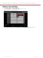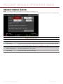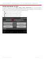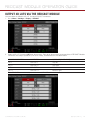
1
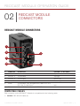
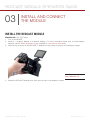
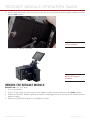
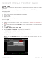
REDCAST Module
O P E R AT I O N G U I D E
REDCAST Module
RED.COM
R E D C A S T M o d u l e O P E R AT I O N G U I D E
TABLE OF CONTENTS
Disclaimer3
Copyright Notice
3
Trademark Disclaimer
3
Compliance Statements
3
Safety Instructions
5
Chapter 1: REDCAST Module Introduction
6
Introduction6
System Requirements
7
Additional Resources
7
Chapter 2: REDCAST Module Connectors
8
REDCAST Module Connectors
8
SDI-OUT Pinout
9
SYNC Pinout
9
TC Pinout
9
Chapter 3: Install and Connect the Module
10
Install the REDCAST Module
10
Remove the REDCAST Module
11
Output Quad UHD or 1080p
12
Set Up Timecode with the REDCAST Module
16
Set Up Genlock with the REDCAST Module
17
Enable a Test Pattern
20
REDCAST Module Status
21
Chapter 4: Load and Use 3D LUTs
22
Compatible 3D LUT Formats
22
Manage 3D LUTs
22
Output 3D LUTs via the REDCAST Module
24
3D LUT Algorithms
25
Chapter 5: REDCAST Module Maintenance
26
Clean REDCAST Module Exterior Surfaces
26
Store REDCAST Module
26
Water Damage
26
Chapter 6: Troubleshoot Your REDCAST Module
27
Err (Error) Link Status
27
Video Does Not Display Correctly
27
No Timecode in Via REDCAST Module
27
Cannot Genlock Via REDCAST Module
28
Genlock Not In Sync When Using Long Cables
28
Can Only Select Quadrant as Output
28
Appendix A: Technical Specifications
29
Appendix B: REDCAST Module Compatibility
30
Supported Frequencies
30
Attach REDCAST Module
30
Compatible RED Devices
30
Compatible Timecode and Genlock Devices
30
Compatible Third-Party Devices
31
Appendix C: REDCAST Module Workflow
32
Essential (Basic) Broadcast Setup
32
Broadcast Setup with SMPTE Fiber Bridge
33
COPYRIGHT © 2015 RED.COM, INC 955-0072, REV-H |
2
R E D C A S T M o d u l e O P E R AT I O N G U I D E
DISCLAIMER
RED has made every effort to provide clear and accurate information in this document, which is provided solely for the user’s information. While thought to be accurate, the information in this document is provided strictly “as is” and RED will not be held responsible
for issues arising from typographical errors or user’s interpretation
of the language used herein that is different from that intended by
RED. All safety and general information is subject to change as a
result of changes in local, federal or other applicable laws.
RED reserves the right to revise this document and make changes
from time to time in the content hereof without obligation to notify
any person of such revisions or changes. In no event shall RED, its
employees or authorized agents be liable to you for any damages
or losses, direct or indirect, arising from the use of any technical or
operational information contained in this document.
For comments or questions about content in this Operation Guide,
please send a detailed email to [email protected].
Increase the separation between the equipment and receiver.
Connect the equipment into an outlet on a circuit different from
that to which the receiver is connected.
Consult the dealer or an experienced radio/TV technician for
help.
In order to maintain compliance with FCC regulations, shielded
cables must be used with this equipment. Operation with non-approved equipment or unshielded cables is likely to result in interference to radio and TV reception. The user is cautioned that changes
and modifications made to the equipment without the approval of
manufacturer could void the users authority to operate this equipment.
NOTE: This device complies with Part 15 of the FCC Rules.
Operations subjected to the following two conditions (1) this device
may not cause harmful interference, and (2) this device must accept
any interference received, including that may cause undesirable interference.
COPYRIGHT NOTICE
COPYRIGHT© 2015 RED.COM, INC.
CAUTION: Regulations of the FCC and FAA
prohibit airborne operation of radio-frequency
wireless devices because there signals could
interfere with critical aircraft instruments.
All trademarks, trade names, logos, icons, images, written material,
code, and product names used in association with the accompanying product are the copyrights, trademarks or other intellectual
property owned and controlled exclusively by RED.COM, INC.
TRADEMARK DISCLAIMER
All other company, brand and product names are trademarks or
registered trademarks of their respective holders. RED has no affiliation to, is not associated or sponsored with, and has no express
rights in third-party trademarks. Torx is a registered trademark of
Acument Intellectual Properties, LLC in the United States or other
countries. DaVinci Resolve is a registered trademark of Blackmagic
Design Pty. Ltd. Adobe is a registered trademark of Adobe Systems
Incorporated. NIPROS is a trademark of Nippon Video Systems
(NVS). Sony is a registered trademark of Sony Electronics Inc. AJA
is a registered trademark of AJA Video Systems, Inc. in the United
States and other countries.
CAUTION: If the device is changed or modified
without permission from RED, the user may
void his or her authority to operate the equipment.
AUSTRALIA AND NEW ZEALAND STATEMENTS
RED declares that the radio equipment described in this document
comply with the following international standards.
IEC 60065 – Product Safety
RED declares digital devices described in this document comply
with the following Australian and New Zealand standards.
COMPLIANCE STATEMENTS
AS/NZS CISPR 22 – Electromagnetic Interference
INDUSTRIAL CANADA EMISSION COMPLIANCE STATEMENTS
AS/NZS 61000.3.2 – Power Line Harmonics
AS/NZS 61000.3.3 – Power Line Flicker
This Class B digital apparatus complies with Canadian ICES-003.
Cet appareil numérique de la classe B est conforme à la norme
NMB-003 du Canada.
FEDERAL COMMUNICATIONS COMMISSION (FCC) STATEMENTS
This equipment has been tested and found to
comply with the limits for a Class B digital
device, pursuant to part 15 of the FCC Rules.
These limits are designed to provide reasonable protection against harmful interference
in a residential installation. This equipment
generates, uses and can radiate radio frequency energy and, if not installed and used
in accordance with the instructions, may cause harmful interference
to radio communications. However, there is no guarantee that interference will not occur in a particular installation. If this equipment
does cause harmful interference to radio or television reception,
which can be determined by turning the equipment off and on, the
user is encouraged to try to correct the interference by one or more
of the following measures:
JAPAN STATEMENTS
This is a Class B product based on the
standard of the Voluntary Control Council
for Interference (VCCI) for information technology equipment. If this equipment is used
near a radio or television receiver in a domestic environment, it may cause radio interference. Install and use the equipment
according to the instruction manual.
Reorient or relocate the receiving antenna.
COPYRIGHT © 2015 RED.COM, INC 955-0072, REV-H |
3
R E D C A S T M o d u l e O P E R AT I O N G U I D E
EUROPEAN UNION COMPLIANCE STATEMENTS
INFORMATION
Products with the CE marking comply with the EMC
Directive (2004/108/EC) and
the Low Voltage Directive
(2006/95/EC) issued by the
Commission of the European Community. Compliance with these directives implies conformity
to the following European Product Family Standards.
EN 55022 (CISPR 22) – Electromagnetic Interference
EN 55024-1 (CISPR 24) – Electromagnetic Immunity
EN 61000-3-2 (IEC610000-3-2) – Power Line Harmonics
EN 61000-3-3 (IEC610000) – Power Line Flicker
EN 60065 (IEC60065) – Product Safety
WASTE ELECTRICAL AND ELECTRONIC EQUIPMENT (WEEE)
new product.
The Waste Electrical and Electronic Equipment (WEEE) mark applies only to countries
within the European Union (EU) and Norway.
This symbol on the product and accompanying documents means that used electrical
and electronic products should not be mixed
with general household waste. For proper
treatment, recovery and recycling, please
take this product to designated collection
points where it will be accepted free of
charge. Alternatively, in some countries you
may be able to return your products to your
local retailer upon purchase of an equivalent
Disposing of this product correctly will help save valuable resources
and prevent any potential negative effects on human health and the
environment, which could otherwise arise from inappropriate waste
handling. Please contact your local authority for further details of
your nearest designated collection point. Penalties may be applicable for incorrect disposal of this waste, in accordance with you
national legislation.
For business users in the European Union, if you wish to discard
electrical and electronic equipment, please contact your dealer or
supplier for further information.
RESPONSIBLE PARTY:
RED Digital Cinema
34 Parker
Irvine, CA 92618
USA
COPYRIGHT © 2015 RED.COM, INC 955-0072, REV-H |
4
R E D C A S T M o d u l e O P E R AT I O N G U I D E
SAFETY INSTRUCTIONS
DO NOT use the camera or accessories near water. Avoid exposing your camera to moisture. The unit is not waterproof,
so contact with water could cause permanent damage to the
unit as well as electric shock and serious injury to the user. DO
NOT use the camera in the rain or under other conditions with
high moisture without appropriate protection, and immediately
remove power source if camera or accessories are exposed to
moisture.
DO NOT bypass the third prong of the grounding-type plug on
the power cord of the AC Power Adapter. A grounding-type
plug has two blades and a third “grounding” prong. The third
prong is provided for your safety. A grounding-type plug shall
be connected to an outlet with a protective earthen connection. If the grounding-type plug does not fit into your outlet,
do not attempt to modify the plug or outlet, consult a qualified
electrician.
Protect all power cords from being pinched, walked on or
driven over by a vehicle. Replace any power cords suspected
of sustaining damage due to crushing or other forms physical
damage.
WARNING: To reduce the risk of fire or electric shock, do not expose the camera to
rain or moisture.
DO NOT expose the DSMC to laser beams, as laser beams may
damage the sensor.
DO NOT expose your camera to excessive vibration or impact
(shock). Be careful not to drop your camera. Internal mechanisms may be damaged by severe shock. Mechanical alignment
of optical elements may be affected by excessive vibration.
ELECTROMAGNETIC INTERFERENCE: The use of devices using radio or other communication waves may result in the malfunction or interference with the unit and/or with audio and
video signals.
Clean only using a dry cloth. When cleaning your camera, remember that it is not waterproof and moisture can damage
electronic circuitry. DO NOT rinse or immerse any element
of the camera, lens or other accessory, keep them dry at all
times. DO NOT use soaps, detergents, ammonia, alkaline
cleaners, and abrasive cleaning compounds or solvents. These
substances may damage lens coatings and electronic circuitry.
Maintain sufficient ventilation—DO NOT block any ventilation
openings or obstruct cooling fan airflow.
CAUTION: Proper camera ventilation requires a minimum 1/2" (1.25 cm) clearance between the camera ventilation
openings and external surfaces. Verify
that objects that can block the fan intake
and exhaust ports do not impede airflow.
Failure to permit adequate airflow may result in overheating of the camera, degraded operation and in extreme situations,
damage to the camera.
DO NOT operate or store near any heat sources such as radiators, heat registers, stoves, or any other apparatus that produce heat. Store in a protected, level and ventilated place.
Avoid exposure to temperature extremes, damp, severe vibration, strong magnetic fields, direct sunlight or local heat sources during storage. Remove any batteries from the camera before storage. Recommended storage and usage temperatures
for your camera, lenses and other accessories are:
‒‒
Operating range: 0°C to 40°C (32°F to 104°F)
‒‒
Storage range: –20°C to 50°C (–4°F to 122°F)
CAUTION: The power cord plug for the AC
Power Adapter is used as the power disconnect. To disconnect all power from the
AC Power Adapter, unplug the power cord
plug from the wall outlet. During use, the
power cord plug should remain easily accessible at all times.
Lithium Ion batteries may be subject to special handling requirements pursuant to federal and local laws. Please refer to
specific shipping instructions included with your battery regarding proper transport of your battery. DO NOT handle your
battery if it is damaged or leaking. Disposal of batteries must
be in accordance with local environmental regulations. For
example, California law requires that all rechargeable batteries must be recycled by an authorized recycle center. Storing
batteries fully charged or in high temperature, conditions may
permanently reduce the life of the battery. Available battery
capacity may also be temporarily lessened after storage in low
temperature conditions.
WARNING: DO NOT expose the battery to
excessive heat.
WARNING: Danger of explosion if an incorrect battery is charged with the RED Charger or is used to power the camera and
accessories. Replace only with the same
or equivalent type battery.
CAUTION: Refer all service and repair to
qualified RED service personnel. To reduce
the risk of electric shock, and damage to
the camera or accessories, DO NOT attempt to perform any servicing other than
any procedures that are recommended in
the operating instructions.
If there are any performance issues with your camera or accessories when operating within this temperature range, please
file a support ticket on support.red.com.
The DSMC Side Handle, Side SSD Module, rear modules and
lens mount are NOT HOT SWAPPABLE, meaning you cannot
remove or install them while the camera is turned on. Before
installing or removing any of these accessories, you MUST turn
off the camera. Failure to do so may result in damage to the
accessory and/or camera BRAIN that will not be covered under
warranty.
COPYRIGHT © 2015 RED.COM, INC 955-0072, REV-H |
5
R E D C A S T M od u l e O P E R AT I O N G U I D E
01
REDCAST MODULE
INTRODUCTION
INTRODUCTION
The REDCAST™ Module (formerly the RED 4K Broadcast Module) provides a 4K Ultra-High Definition (UHD)
video stream, enabling you to capture and view action in real-time. The REDCAST Module uses four (4) 1080p
3G-SDI output connections to broadcast 4K video at up to 59.94 frames per second (FPS).
Alternately, you can stream a full-frame 1080p video out of each 3G-SDI connector, providing four (4) additional
HD-SDI monitoring and recording paths.
For the first time, the unrivaled crisp and detailed images created by the EPIC DRAGON ® and SCARLET
DRAGON ® cameras can be broadcasted, creating a refined 4K viewing experience. The REDCAST Module adds
to the arsenal of features the EPIC DRAGON and SCARLET DRAGON offer. In addition to streaming a live 4K
UHD video feed from the REDCAST Module, the BRAIN ® can simultaneously:
Record to SSD at 6K, 5K, or 4K.
Live stream at up to 1080p via the HD-SDI connector.
Live stream at up to 1080p via the HDMI connector.
Five (5) 1/4-20 mounting holes are built into the top of the module, allowing for various mechanical peripherals
to be attached.
You can apply 3D LUTs to the 3G-SDI outputs on the REDCAST Module.
NOTE: The REDCAST Module features differ between v5.3 and v6.0 firmware. This operation guide describes
features available in both firmware versions. Unless noted otherwise, all screen shots are from v6.0.
REDCAST Module
COPYRIGHT © 2015 RED.COM, INC 955-0072, REV-H |
6
R E D C A S T M od u l e O P E R AT I O N G U I D E
SYSTEM REQUIREMENTS
The REDCAST Module is ONLY compatible with EPIC DRAGON and SCARLET DRAGON. The
REDCAST Module is NOT compatible with EPIC MYSTERIUM-X ® or SCARLET MYSTERIUM-X ® .
The REDCAST Module requires either the Module Adaptor or the +1 Adaptor Module to be connected to
the BRAIN.
The REDCAST Module requires that your DSMC ® is on firmware v5.2.28 or later.
Using a 3D LUT requires that your DSMC is on firmware v6.0 or later.
Streaming full-frame 1080p video from the 3G-SDI connectors requires that your DSMC is on firmware v6.0
or later.
ADDITIONAL RESOURCES
The following resources offer additional information about RED ® , the DSMC system, and the RED community:
RED.com: Check the official RED website for the latest information about RED products.
RED Learn Articles: RED offers in-depth technical articles about RED cameras, post-production, and digital
cinematography.
RED.com/downloads: Go to the RED Downloads page to download the latest firmware, operation guides,
and post-production software.
DSMC Toolkit: Go to the RED Downloads page to find the DSMC Toolkit, which offers many helpful tools and
resources to customize and improve your DSMC workflow.
Support.red.com: Check the RED SUPPORT site for FAQs, or to file a support ticket.
Bomb Squad Support: For more information, contact your Bomb Squad representative.
In-Camera Help: Select the Help button on an in-camera screen to open up the help for that screen.
Reduser.net: Discuss all things RED on the REDUSER third-party forum.
COPYRIGHT © 2015 RED.COM, INC 955-0072, REV-H |
7
R E D C A S T M od u l e O P E R AT I O N G U I D E
02
REDCAST MODULE
CONNECTORS
REDCAST Module CONNECTORS
1
2
5
3
4
6
#
CONNECTOR
DESCRIPTION
QUADRANT (IN UHD MODE)
1
SDI-OUT 1
75 ohm BNC
Top left
2
SDI-OUT 2
75 ohm BNC
Top right
3
SDI-OUT 3
75 ohm BNC
Bottom left
4
SDI-OUT 4
75 ohm BNC
Bottom right
5
SYNC
75 ohm BNC; sync and genlock in; SMPTE ST 274;
RS 170A Tri-Level Sync
N/A
6
TC
75 ohm BNC; timecode in; SMPTE ST 12-2
N/A
COMPATIBLE CABLES
Each connector on the REDCAST™ Module is compatible with the following cable:
790-0341: RED HD-SDI Cable (6')
COPYRIGHT © 2015 RED.COM, INC 955-0072, REV-H |
8
R E D C A S T M od u l e O P E R AT I O N G U I D E
SDI-OUT PINOUT
Each SDI OUT port outputs an uncompressed 1920 × 1080p Level-A YCbCr 4:2:2 10-bit (Rec 709) video feed.
In UHD mode, each SDI OUT port outputs an image quadrant. When each quadrant is combined, the four (4)
outputs form a 3840 × 2160p (4K UHD) image.
75 OHM BNC CONNECTOR 1
PIN
SIGNAL
DESCRIPTION
DIRECTION
Center
3G-SDI
SMPTE ST 424
Out
Shield/Screen
GROUND
Camera ground
N/A
1. The SDI output is progressive scan (p); it does not support progressive segmented frame (PsF) or interlaced (i) scan formats.
SYNC PINOUT
75 OHM BNC CONNECTOR
PIN
SIGNAL
DESCRIPTION
DIRECTION
Center
SYNC
SMPTE ST 274
In
RS 170A Tri-Level Sync
Shield/Screen
GROUND
Camera ground
N/A
TC PINOUT
75 OHM BNC CONNECTOR
PIN
SIGNAL
DESCRIPTION
DIRECTION
Center
TIMECODE
SMPTE ST 12-2
In
Shield/Screen
GROUND
Camera ground
N/A
COPYRIGHT © 2015 RED.COM, INC 955-0072, REV-H |
9
R E D C A S T M od u l e O P E R AT I O N G U I D E
03
INSTALL AND CONNECT
THE MODULE
INSTALL THE REDCAST MODULE
REQUIRED TOOL: T20 Torx ® driver
1. Turn off the BRAIN ® .
2. Install a +1 Adaptor Module or a Module Adaptor. For more information about how to install adaptor
modules, see the DSMC Operation Guide, available at www.red.com/downloads.
3. Insert the lip at the top of the REDCAST™ Module into the recess at the top of the adaptor module.
Insert Module Lip
4. Rotate the REDCAST Module down flush with the rear of the adaptor module.
COPYRIGHT © 2015 RED.COM, INC 955-0072, REV-H |
10
R E D C A S T M od u l e O P E R AT I O N G U I D E
5. Apply pressure and use a T20 Torx driver to turn the lock on the bottom of the adaptor module clockwise
into the Lock position.
Lock In Module
The REDCAST Module is secured.
REDCAST Module
Installed
REMOVE THE REDCAST Module
REQUIRED TOOL: T20 Torx ® driver
1. Turn off the BRAIN.
2. Use a T20 Torx driver to turn the lock on the adaptor module counter-clockwise to the Unlock position.
3. Rotate the REDCAST Module upwards and down to disengage the lip at the top of the module from the
adaptor module.
4. Remove the REDCAST Module from the adaptor module.
COPYRIGHT © 2015 RED.COM, INC 955-0072, REV-H |
11
R E D C A S T M od u l e O P E R AT I O N G U I D E
OUTPUT QUAD UHD OR 1080P
With the REDCAST Module, you can output the following:
“Output Quad UHD” on page 12
“Set Up 1080p” on page 14
OUTPUT QUAD UHD
This section explains how to output 4K Ultra-High Definition (UHD) via the REDCAST Module.
REQUIRED ITEMS
DSMC ® BRAIN
Adaptor module (either a +1 Adaptor Module or a Module Adaptor)
REDCAST Module
Four (4) 3G/HD-SDI cables
Quad 3G/HD-SDI device
SET UP QUAD UHD 3G/HD-SDI
1. Turn the BRAIN off.
2. Install the REDCAST Module on the BRAIN. For more information, go to “Install the REDCAST Module” on
page 10.
3. Use four (4) 3G/HD-SDI cables to connect the four (4) SDI-OUT ports on the REDCAST Module to the four
(4) 3G/HD-SDI IN ports on a quad 3G/HD-SDI device.
NOTE: Be careful to connect each cable from the REDCAST Module to the appropriate connector on the
device. For example, connect SDI-OUT 1 on the REDCAST Module (top left quadrant) to 3G/HD-SDI IN
1 on the device.
4. Turn on the BRAIN.
5. Go to Menu > Settings > Project > Format > UHD.
The UHD menu lists the formats that are capable of displaying on a 4K display.
6. Select the Resolution and Aspect Ratio. Options depend on the camera type:
‒ ‒ EPIC DRAGON ® : 6K 16:9 (HD); 5K 16:9 (HD); 4K 16:9 (HD)
‒ ‒ SCARLET DRAGON ® : 5K 16:9 (HD); 4K 16:9 (HD)
NOTE: The REDCAST Module scales down to the output resolution you select in Step 9. However, the
resolution you select in this step is recorded to the SSD.
COPYRIGHT © 2015 RED.COM, INC 955-0072, REV-H |
12
R E D C A S T M od u l e O P E R AT I O N G U I D E
7. Select Set Format.
NOTE: You must select Set Format to apply the format. Closing the menu any other way DOES NOT apply
the format.
8. Select a Recording Frame Rate (Sensor Frame Rate). Available menus are determined by DSMC firmware:
‒ ‒ v5.3: Menu > Settings > Project > Frame Rates > Sensor Frame Rate
‒ ‒ v6.0: Menu > Settings > Display > REDCAST > FrmRate
NOTE: Ensure that the Recording Frame Rate (Sensor Frame Rate) matches the Project Time Base.
9. Select your output:
A. Go to Menu > Settings > Display > REDCAST.
B. Select UHD from the Output drop-down menu.
COPYRIGHT © 2015 RED.COM, INC 955-0072, REV-H |
13
R E D C A S T M od u l e O P E R AT I O N G U I D E
OUTPUT 1080P
NOTE: Streaming full-frame 1080p video from the 3G-SDI connectors requires that your DSMC is on firmware
v6.0 or later.
This section explains how to output 1080p from each SDI-OUT connector on the REDCAST Module.
REQUIRED ITEMS
DSMC BRAIN
Adaptor module (either a +1 Adaptor Module or a Module Adaptor)
REDCAST Module
3G/HD-SDI cables
HD-SDI monitors or recording devices
SET UP 1080P
1. Turn the BRAIN off.
2. Install the REDCAST Module on the BRAIN. For more information, go to “Install the REDCAST Module” on
page 10.
3. Use 3G/HD-SDI cables to connect each SDI-OUT port you plan on using to an HD-SDI monitor or recording
device.
4. Turn on the BRAIN.
5. Go to Menu > Settings > Project > Format > UHD.
The UHD menu lists the formats that are capable of displaying on a 4K display.
6. Select the Resolution and Aspect Ratio. Options depend on the camera type:
‒ ‒ EPIC DRAGON: 6K 16:9 (HD); 5K 16:9 (HD); 4K 16:9 (HD)
‒ ‒ SCARLET DRAGON: 5K 16:9 (HD); 4K 16:9 (HD)
NOTE: The REDCAST Module scales down to the output resolution you select in Step 9. However, the
resolution you select in this step is recorded to the SSD.
7. Select Set Format.
NOTE: You must select Set Format to apply the format. Closing the menu any other way DOES NOT apply
the format.
COPYRIGHT © 2015 RED.COM, INC 955-0072, REV-H |
14
R E D C A S T M od u l e O P E R AT I O N G U I D E
8. Go to Menu > Settings > Display > REDCAST.
9. Select 4x 1080p from the Output drop-down menu.
10. Select a frame rate from the FrmRate drop-down menu.
NOTE: Ensure that the Recording Frame Rate matches the Project Time Base.
COPYRIGHT © 2015 RED.COM, INC 955-0072, REV-H |
15
R E D C A S T M od u l e O P E R AT I O N G U I D E
SET UP TIMECODE WITH THE REDCAST Module
The REDCAST Module has BNC TC (timecode) and SYNC ports that support incoming timecode signals. This
section describes how to set up the camera to receive timecode signals from an external timecode generator
via the REDCAST Module.
NOTE: When a REDCAST Module is installed, you can still receive timecode via the SYNC port on the BRAIN.
For more information, see the DSMC Operation Guide, available at www.red.com/downloads.
1. Set up the REDCAST Module. For more information, go to “Output Quad UHD or 1080p” on page 12.
2. Connect the REDCAST Module to a timecode generator:
A. Ensure that the timecode generator is off.
B. Use a 75 Ω coaxial cable to connect the TC port on the REDCAST Module to the TIMECODE port (or
equivalent timecode output port) on the compatible timecode generator.
C. On the timecode generator, set the frames per second to the Recording Frame Rate (Sensor Frame
Rate) you are using for the project.
NOTE: Ensure that the frame rate matches the camera’s Recording Frame Rate (Sensor Frame Rate) and
Project Time Base.
D. Turn on the timecode generator.
3. Set up the timecode source in the camera:
A. Go to Menu > Settings > Project > Timecode.
B. Select External: Rear Module from the Time Code Source drop-down menu.
The TC indicator in the Lower Status Row illuminates green.
√
COPYRIGHT © 2015 RED.COM, INC 955-0072, REV-H |
16
R E D C A S T M od u l e O P E R AT I O N G U I D E
SET UP GENLOCK WITH THE REDCAST MODULE
The REDCAST Module has a BNC SYNC port that supports incoming sync signals. This section describes
how to set up the camera to receive sync signals from an external genlock device via the REDCAST Module.
NOTE: When a REDCAST Module is installed, you can still receive sync signals via the SYNC port on the
BRAIN. For more information, see the DSMC Operation Guide, available at www.red.com/downloads.
1. Set up the REDCAST Module. For more information, go to “Output Quad UHD or 1080p” on page 12.
2. Connect the REDCAST Module to a genlock device:
A. Ensure that the genlock device is off.
B. Use a 75 Ω coaxial cable to connect the SYNC port on the REDCAST Module to a compatible genlock
device.
C. Turn on the genlock device.
3. Go to Menu > Settings > Display > REDCAST.
4. Select On from the Genlock drop-down menu.
COPYRIGHT © 2015 RED.COM, INC 955-0072, REV-H |
17
R E D C A S T M od u l e O P E R AT I O N G U I D E
5. Set up the genlock source in the camera:
A. Go to Menu > Settings > Setup > GPIO/Sync.
B. Select Rear Module from the Genlock Source drop-down menu.
The GEN indicator in the Lower Status Row illuminates green.
6. If the video feed is delayed, set the genlock offset. For more information, go to “Set Genlock Offset” on
page 19.
COPYRIGHT © 2015 RED.COM, INC 955-0072, REV-H |
18
R E D C A S T M od u l e O P E R AT I O N G U I D E
SET GENLOCK OFFSET
If the video feed is delayed, adjust the genlock offset for the REDCAST Module.
1. Go to one of the following menus (available menus are determined by DSMC firmware):
‒ ‒ v5.3 or v6.0: Menu > Settings > Display > REDCAST
‒ ‒ v6.0: Menu > Settings > Display > Monitor Control > Advanced > REDCAST
2. Select the genlock offset from the Genlock drop-down menu. Range is –8,000 pixels to 10 pixels. Default
is 0 pixels.
‒ ‒ Negative offset: Advances the video, so the video reaches the switcher earlier than it would otherwise.
‒ ‒ Positive offset: Advances the video, so the video reaches the switcher later than it would otherwise.
3. Continue to adjust the genlock offset until the video ingest equipment indicates that the video signal aligns
with the genlock signal.
COPYRIGHT © 2015 RED.COM, INC 955-0072, REV-H |
19
R E D C A S T M od u l e O P E R AT I O N G U I D E
ENABLE A TEST PATTERN
1. Go to Menu > Settings > Display > REDCAST.
2. Select Test Pattern from the Test Pattern / Video drop-down menu.
The SDI ports output SMPTE color bars.
3. To switch back to the video feed, select Video from the Test Pattern / Video drop-down menu.
COPYRIGHT © 2015 RED.COM, INC 955-0072, REV-H |
20
R E D C A S T M od u l e O P E R AT I O N G U I D E
REDCAST Module STATUS
NOTE: The module status information is only visible in firmware v5.3.
The REDCAST menu provides status information about the module. These statuses are helpful for troubleshooting.
REDCAST Module STATUS
#
STATUS ITEM
DESCRIPTION
1
Upgrade
Hardware and firmware revision of the module.
2
Link Status
Connection status between BRAIN and the module. For more information about
an “Err” (error) status, go to “Err (Error) Link Status” on page 27.
3
Chip Temperature
Temperature of the module’s application-specific integrated circuit (ASIC).
4
Board Temperature
Internal temperature of the module.
5
Fan Speed
Current fan speed as a percentage.
COPYRIGHT © 2015 RED.COM, INC 955-0072, REV-H |
21
R E D C A S T M od u l e O P E R AT I O N G U I D E
04
LOAD AND
USE 3D LUTS
You can output a 3D lookup table (LUT) via each SDI-OUT connector on the REDCAST™ Module.
NOTE: Using a 3D LUT requires that your DSMC ® is on firmware v6.0 or later.
COMPATIBLE 3D LUT FORMATS
The REDCAST Module is compatible with the following 3D LUTs:
DaVinci Resolve ® 3D Cube LUT (.cube)
IRIDAS/Adobe ® 3D Cube LUT (.cube)
Nucoda CMS 3D LUT (.cms)
The REDCAST Module is compatible with the following 3D LUT formats:
17x17x17
26x26x26
32x32x32
33x33x33
MANAGE 3D LUTS
To manage 3D LUTs, go to Menu > Settings > Display > Monitor Control.
3D LUTs can be stored on the camera or transferred to SSD, so that you can build a library of 3D LUTs, or
quickly copy 3D LUTs from one camera to another via SSD.
In Camera: 3D LUTs that are saved internally on the camera.
On Media \luts: 3D LUTs that are on the SSD.
COPYRIGHT © 2015 RED.COM, INC 955-0072, REV-H |
22
R E D C A S T M od u l e O P E R AT I O N G U I D E
EXPORT AND IMPORT 3D LUTS
To export and import 3D LUTs, go to Menu > Settings > Display > Monitor Control. 3D LUTs can be stored on
the camera or transferred to SSD to be shared with other cameras. When exporting 3D LUTs from camera to
an SSD, the 3D LUTs are saved to a folder on the SSD called “luts”. When importing 3D LUTs from an SSD to
camera, the 3D LUTs must be stored on the SSD in a folder called “luts”.
All
: Export selected 3D LUT from camera to SSD.
: Export all 3D LUTs from camera to SSD.
: Import selected 3D LUT from SSD to camera.
All: Import all 3D LUTs from SSD to camera.
COPYRIGHT © 2015 RED.COM, INC 955-0072, REV-H |
23
R E D C A S T M od u l e O P E R AT I O N G U I D E
OUTPUT 3D LUTS VIA THE REDCAST Module
You can select a different 3D LUT for each SDI-OUT connector.
1. Go to Menu > Settings > Display > REDCAST.
2. Select a 3D LUT from each LUT drop-down menu. Each drop-down menu corresponds to a REDCAST Module
connector and output quadrant (if in UHD mode), as described in the table below:
LUT DROP-DOWN MENU
CONNECTOR
QUADRANT (IN UHD MODE)
LUT 1
SDI-OUT 1
Top left
LUT 2
SDI-OUT 2
Top right
LUT 3
SDI-OUT 3
Bottom left
LUT 4
SDI-OUT 4
Bottom right
Each SDI-OUT connector outputs the selected 3D LUT.
COPYRIGHT © 2015 RED.COM, INC 955-0072, REV-H |
24
R E D C A S T M od u l e O P E R AT I O N G U I D E
3D LUT ALGORITHMS
The camera processes 3D LUTs using the following logic:
If the input RGB triplets do not coincide with a knee point in the 3D LUT, the camera uses tetrahedral
interpolation to estimate RGB output triplets.
The camera performs all 3D LUT mathematical operations with 16-bit precision.
These algorithms ensure accuracy, but that accuracy may cause the results to be different than the results from
other programs applying identical 3D LUTs. RED ® recommends reviewing the output to ensure that the results
match the needs of your project.
COPYRIGHT © 2015 RED.COM, INC 955-0072, REV-H |
25
R E D C A S T M od u l e O P E R AT I O N G U I D E
05
REDCAST Module
MAINTENANCE
All RED ® products are designed for rugged durability, but precision instruments demand proper care. Follow the
instructions in this chapter to clean, maintain, and store the REDCAST™ Module.
WARNING: DO NOT rinse or immerse the REDCAST Module in water. Keep dry at all times.
WARNING: DO NOT use soaps, detergents, ammonia, acetone, alkaline cleaners, abrasive cleaning compounds,
or solvents. These substances may damage lens coatings and electronic circuitry.
WARNING: DO NOT attempt to modify, dismantle, or open your REDCAST Module as doing so may expose you
to electric shock and serious injury. There are no user-serviceable parts inside. Alteration or repairs made to
the REDCAST Module, except by a RED authorized service facility, voids all warranties.
CLEAN REDCAST Module EXTERIOR SURFACES
Use a gas duster to clean around the recesses on the exterior of the REDCAST Module.
Clean with a damp, lint-free cloth. When cleaning your REDCAST Module, remember that the device is
not waterproof and moisture can damage electronic circuitry.
STORE REDCAST Module
WARNING: DO NOT store the REDCAST Module in any place with extreme temperatures, direct sunlight, high
humidity, severe vibration, or strong magnetic fields.
WATER DAMAGE
If your device has come in contact with water or you suspect water damage, contact your Bomb Squad
representative immediately.
WARNING: DO NOT attempt to power any device that may have water damage.
WARNING: DO NOT place the device in a container of rice, silica gel, or desiccant packets in an attempt to dry
the device.
COPYRIGHT © 2015 RED.COM, INC 955-0072, REV-H |
26
R E D C A S T M od u l e O P E R AT I O N G U I D E
06
TROUBLESHOOT YOUR
REDCAST Module
ERR (ERROR) LINK STATUS
SYMPTOM
NOTE: The Link Status is only visible in firmware v5.3.
The REDCAST menu shows that the Link Status for either the Camera or Module is “Err” (error).
POTENTIAL RESOLUTION
Reboot the BRAIN ® .
Remove the REDCAST™ Module and the adaptor module. Check the module connectors. If the connectors
have dust or debris, clean the connectors. If any connectors are damaged, contact your Bomb Squad
representative.
Use a different adaptor module.
VIDEO DOES NOT DISPLAY CORRECTLY
SYMPTOMS
Image does not display.
Image freezes.
Quadrants are not in sync.
POTENTIAL RESOLUTIONS
Go to Menu > Settings > Display > REDCAST and select Video Reset (v5.3) or SDI Reset (v6.0 or later). This
resets the video connection.
Go to Menu > Settings > Project > Format > UHD and re-select the Resolution. Then select Set Format.
NO TIMECODE IN VIA REDCAST Module
SYMPTOMS
Camera does not receive timecode signal when a timecode generator is connected to the REDCAST Module.
The TC indicator does not illuminate green.
POTENTIAL RESOLUTIONS
Ensure that each of the following has the same frame rate:
Recording Frame Rate (Sensor Frame Rate)
Project Time Base
Timecode generator
COPYRIGHT © 2015 RED.COM, INC 955-0072, REV-H |
27
R E D C A S T M od u l e O P E R AT I O N G U I D E
CANNOT GENLOCK VIA REDCAST Module
SYMPTOMS
Cannot genlock the camera when a genlock device is connected to the REDCAST Module.
The GEN indicator does not illuminate green.
POTENTIAL RESOLUTION
Ensure that each of the following has the same frame rate:
Recording Frame Rate (Sensor Frame Rate)
Project Time Base
GENLOCK NOT IN SYNC WHEN USING LONG CABLES
SYMPTOM
The camera is receiving an incoming genlock signal, but third-party broadcast infrastructure (such as a switcher
or video ingest equipment) indicates that the video does not align with the genlock signal.
Since this issue occurs when the video reaches third-party infrastructure, the camera does not indicate any
errors due to this issue.
EXPLANATION
If using long cables to connect the REDCAST Module to a genlock device or the video ingest point, the video
may be delayed once it reaches the video ingest point.
For example, using a 1 km fiber optic cable to connect the REDCAST Module to a switcher creates a 2 km
round trip for the video signal. This results in a round trip delay of about 10,000 nanoseconds. For 59.94 FPS,
one pixel time is 6.73 nanoseconds, so the round trip delay is about 1485 pixels.
POTENTIAL RESOLUTIONS
Offset the signal in the broadcast truck using third-party infrastructure.
Offset the video signal in-camera to align it with the genlock signal. For more information, go to “Set
Genlock Offset” on page 19.
CAN ONLY SELECT QUADRANT AS OUTPUT
SYMPTOM
In firmware v5.3, the only Output option in the REDCAST menu is Quadrant.
EXPLANATION
This is normal behavior. In firmware v5.3, the only option in the Output menu is Quadrant. To access additional
options, upgrade the DSMC ® firmware to v6.0.
COPYRIGHT © 2015 RED.COM, INC 955-0072, REV-H |
28
R E D C A S T M od u l e O P E R AT I O N G U I D E
A
TECHNICAL
SPECIFICATIONS
SPECIFICATION
DESCRIPTION
Weight
1.606 lb (728.5 g)
Dimensions
Height: 4.29" (109 mm)
Width: 5.43" (138 mm)
Depth: 2.24" (56.8 mm)
Additional Mounting
5x 1/4-20 mounting points on top
Construction
Machined, Tooled (Early models are machined)
Material
Aluminum
Coating
Black powder coat
Operating Temperature
0°C to 40°C (32°F to 104°F)
Storage Temperature
–20°C to 50°C (–4°F to 122°F)
Operating Humidity Range
0% to 85%, non-condensing
Storage Humidity Range
0% to 85%, non-condensing
Broadcast Output Formats
3840 × 2160p (4K UHD), up to 59.94 FPS
4x 1080p (HD), up to 59.94 FPS
Broadcast Output Frame Rates 23.98p, 24p, 25p, 29.97p, 50p, 59.94p
Recording Format (Video)
Currently selected resolution settings, up to 6K up to 59.94 FPS
Audio Out
N/A. Module does not currently support audio through SDI
SMPTE Timecode
Timecode (TC)
3G/HD-SDI Output
4x BNC (rated for 3G-SDI) 1
4x uncompressed 1920 × 1080p Level-A YCbCr 4:2:2 10-bit video (Rec 709) 2
3G-SDI (3G): Meets SMPTE ST 424 and 425 when frame rates > 30 Hz 3
HD-SDI (1.5G): Meets SMPTE ST 292 when frame rates < 30 Hz 3
HD (1080p): SMPTE ST 274 2
Genlock In
1x BNC, 75 Ω
Timecode In
1x BNC, 75 Ω, SMPTE ST 12-2
Power Consumption
Approximately 15 W
DSMC ® Compatibility
RED DRAGON ® sensor based ONLY (NOT MYSTERIUM-X ® )
Firmware Requirement
5.2.28 or later
1. In UHD mode, each SDI-OUT connector sends one (1) quadrant of the UHD video.
2. Applicable to each SDI-OUT connector.
3. Applicable to the full 4K UHD video.
COPYRIGHT © 2015 RED.COM, INC 955-0072, REV-H |
29
R E D C A S T M od u l e O P E R AT I O N G U I D E
B
REDCAST Module
COMPATIBILITY
SUPPORTED FREQUENCIES
SUPPORTED FREQUENCIES 1
FREQUENCY (HZ)
SMPTE STANDARD
23.98, 24.00, 25.00, 29.97, 30.00
HD-SDI
SMPTE ST 292 (1.485 Gbps)
50.00, 59.94
3G-SDI
SMPTE ST 424 (2.970 Gbps)
SMPTE ST 425 (2.970 Gbps)
1. Ensure you select a frequency supported by your monitor.
ATTACH REDCAST Module
You can dock the REDCAST™ Module to the following devices:
Module Adaptor
+1 Adaptor Module
COMPATIBLE RED DEVICES
You can attach the following devices directly to the back of the REDCAST Module:
Pro Battery Module (Dual)
Pro Battery Module (Quad)
Quickplate Adaptor
Quickplate Module
REDMOTE ®
REDVOLT XL Module
COMPATIBLE TIMECODE AND GENLOCK DEVICES
The REDCAST Module is compatible with the same timecode generators and genlock devices as the DSMC ®
BRAIN ® . For more information about what devices are compatible with the DSMC BRAIN, see the DSMC
Operation Guide, available at www.red.com/downloads.
COPYRIGHT © 2015 RED.COM, INC 955-0072, REV-H |
30
R E D C A S T M od u l e O P E R AT I O N G U I D E
COMPATIBLE THIRD-PARTY DEVICES
The following devices are compatible with the REDCAST Module. Other devices may also be compatible, but
have not been tested by RED ® .
Nipros ® LS-750GT 4K+X Optical Fiber Camera Adapter
Nipros LS-750 GTS 4K+X Optical Fiber Camera Adapter
Nipros LS-850 4K+X Base Station (when used with the Nipros LS-750GT or Nipros LS-750 GTS)
Sony ® RCP-1500 (when used with a compatible adaptor and Ethernet switcher)
AJA ® Hi5-4K SDI to HDMI Converter
Quad 4K-compliant SMPTE fiber adaptors
Quad 4k-compliant peripheral recorders
Quad 4k-compliant broadcast switchers
COPYRIGHT © 2015 RED.COM, INC 955-0072, REV-H |
31
R E D C A S T M od u l e O P E R AT I O N G U I D E
C
REDCAST Module
WORKFLOW
This section describes the basic setup and workflow for using the REDCAST™ Module in different environments.
For more information about different setup and integration options, go to www.red.com/products/4k-broadcast.
ESSENTIAL (BASIC) BROADCAST SETUP
This section describes an example setup and workflow for connecting the REDCAST Module directly to a
monitor.
ESSENTIAL (BASIC) SETUP: RECOMMENDED EQUIPMENT
REDCAST Module (required)
+1 Adaptor Module or Module Adaptor (required)
Four (4) 3G/HD-SDI cables (required)
4K recorder
Monitor (required for playback)
RED ® Touch 7.0" LCD
DSMC Tactical Top Plate 2.0
ESSENTIAL (BASIC) INSTALLATION
The example installation below describes how to record to an external 4K recorder while viewing the live image
on a monitor. If your setup does not require using either an external 4K recorder or a monitor, skip the steps
related to the device.
1. Set up the camera:
A. Set up the camera rig.
B. Install the REDCAST Module on the BRAIN ® . For more information, go to “Install the REDCAST Module”
on page 10.
2. Connect all four (4) SDI-OUT ports on the REDCAST Module to four (4) 3G/HD-SDI IN ports on a 4K recorder
using four (4) 3G/HD-SDI cables.
3. Connect the 4K recorder to a monitor.
NOTE: This setup may require a signal converter. Check the input/output connectors on your devices to
determine what cables and convertors are necessary.
COPYRIGHT © 2015 RED.COM, INC 955-0072, REV-H |
32
R E D C A S T M od u l e O P E R AT I O N G U I D E
BROADCAST SETUP WITH SMPTE FIBER BRIDGE
This section describes example setups and workflows for using the REDCAST Module in configurations that
incorporate a SMPTE fiber bridge and a fiber adaptor. Example configurations include:
Handheld/EFP (electronic field production) broadcast setup
Fixed/studio broadcast setup
HANDHELD/EFP SETUP: RECOMMENDED EQUIPMENT
REDCAST Module (required)
+1 Adaptor Module or Module Adaptor (required)
Four (4) 3G/HD-SDI cables (required)
RED WIRELESS MOTOR DRIVER (W.M.D.)
Iris motor
Cinema zoom lens with servo drive unit and power cable
Iris rods and rod mount
RED Touch 7.0" LCD
RED BOMB EVF ®
Tally light
Shoulder pad
Fiber adaptor (required)
Fiber adaptor base station (required)
311M SMPTE hybrid fiber cable (required)
Ethernet cable (required for camera control)
Remote camera panel (RCP) system (required for camera control)
FIXED/STUDIO SETUP: RECOMMENDED EQUIPMENT
REDCAST Module (required)
+1 Adaptor Module or Module Adaptor (required)
Four (4) 3G/HD-SDI cables (required)
RED WIRELESS MOTOR DRIVER (W.M.D.)
Lens motors
Zoom and focus demands
Display viewfinder
Headset intercom
Sled
Tripod
Fiber adaptor (required)
Fiber adaptor base station (required)
311M SMPTE hybrid fiber cable (required)
Ethernet cable (required for camera control)
Remote camera panel (RCP) system (required for camera control)
COPYRIGHT © 2015 RED.COM, INC 955-0072, REV-H |
33
R E D C A S T M od u l e O P E R AT I O N G U I D E
INSTALLATION WITH SMPTE FIBER BRIDGE
The example installation below describes how to broadcast live content using a SMPTE fiber bridge and a fiber
adaptor. If your setup does not require camera control, skip the steps related to the device.
1. Set up the camera:
A. Set up the camera rig.
B. Install the REDCAST Module on the BRAIN. For more information, go to “Install the REDCAST Module”
on page 10.
C. Connect all four (4) SDI-OUT ports on the REDCAST Module to four (4) 3G/HD-SDI IN ports on a fiber
adaptor using four (4) 3G/HD-SDI cables.
2. Set up genlock. For more information, go to “Set Up Genlock with the REDCAST Module” on page 17.
3. Set up the truck or control center:
A. Connect the fiber adaptor to a fiber adaptor base station using a 311M SMPTE hybrid fiber cable.
B. Connect the fiber adaptor base station to an RCP system via an Ethernet cable.
NOTE: The DSMC ® provides a 1000BASE-T (IEEE 802.3ab) gigabit Ethernet connection.
COPYRIGHT © 2015 RED.COM, INC 955-0072, REV-H |
34
RED DIGITAL CINEMA
COPYRIGHT© 2015 RED.COM, INC.
All trademarks, trade names, logos, icons, images, written material, code and product names used in
association with the accompanying product are the copyrights, trademarks or other intellectual property owned
and controlled exclusively by RED.COM, INC.