1
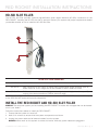
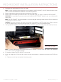
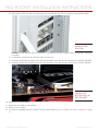
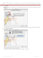
RED ROCKET
I N S TA L L AT I O N I N S T R U C T I O N S
RED ROCKET
RED.COM
R E D R O C K E T I N S TA L L AT I O N I N S T R U C T I O N S
TABLE OF CONTENTS
Disclaimer3
Copyright Notice
3
Trademark Disclaimer
3
Compliance Statements
3
Safety Instructions
4
Chapter 1: RED ROCKET Introduction
5
Scope of These Instructions
5
System and Hardware Requirements 5
RED ROCKET Components
6
How to Handle the RED ROCKET
6
Additional Resources
6
Chapter 2: Install RED ROCKET
7
Thunderbolt Chassis Considerations
7
Required Tools
7
RED ROCKET Board
8
HD-SDI Slot Filler
9
Install the RED ROCKET and HD-SDI Slot Filler
9
Chapter 3: Install Driver and Firmware
12
Download Driver and Firmware
12
Install RED ROCKET Driver
12
Upgrade RED ROCKET Firmware
19
Validate RED ROCKET Installation
21
Chapter 4: Set Up RED ROCKET in REDCINE-X PRO
24
Set Up Decoding and Error Message Preferences 24
Set Up Video Out
25
Chapter 5: Troubleshoot Your RED ROCKET
26
Warning about x8 Lane Requirement
26
RED ROCKET Out of Date
26
Thunderbolt Chassis Installations
27
Appendix A: Technical Specifications
28
Technical Data
28
Hardware Specifications
28
Supported Input Formats
29
Appendix B: DVI-I Cable Pinout
30
Digital Video Interface
30
Appendix C: Video Rasters
31
Supported Output Video Rasters
31
COPYRIGHT © 2015 RED.COM, INC 955-0035, REV-D |
2
R E D R O C K E T I N S TA L L AT I O N I N S T R U C T I O N S
DISCLAIMER
RED has made every effort to provide clear and accurate information
in this document, which is provided solely for the user’s information.
While thought to be accurate, the information in this document is
provided strictly “as is” and RED will not be held responsible for issues arising from typographical errors or user’s interpretation of the
language used herein that is different from that intended by RED.
All safety and general information is subject to change as a result of
changes in local, federal or other applicable laws.
NOTE: Connecting this device to peripheral devices that do not comply with Class A requirements or using an unshielded peripheral data
cable could also result in harmful interference to radio or television
reception. The user is cautioned that any changes or modifications
not expressly approved by the party responsible for compliance
could void the user’s authority to operate this equipment. To ensure
that the use of this product does not contribute to interference, it is
necessary to use shielded I/O cables.
RED reserves the right to revise this document and make changes
from time to time in the content hereof without obligation to notify
any person of such revisions or changes. In no event shall RED, its
employees or authorized agents be liable to you for any damages
or losses, direct or indirect, arising from the use of any technical or
operational information contained in this document.
For comments or questions about content in this Operation Guide,
please send a detailed email to [email protected].
COPYRIGHT NOTICE
COPYRIGHT© 2015 RED.COM, INC.
All trademarks, trade names, logos, icons, images, written material,
code, and product names used in association with the accompanying product are the copyrights, trademarks or other intellectual
property owned and controlled exclusively by RED.COM, INC.
TRADEMARK DISCLAIMER
All other company, brand, and product names are trademarks or
registered trademarks of their respective holders. RED has no affiliation to, is not associated with or sponsored by, and has no express rights in third-party trademarks. The terms HMDI and HDMI
High-Definition Multimedia Interface, and the HDMI Logo are trademarks or registered trademarks of HDMI Licensing LLC in the Untied
States and other countries. Mac, Mac Pro, and OS X are registered
trademarks of Apple Inc., registered in the U.S. and other countries.
Windows and Windows Vista are registered trademarks of Microsoft
Corporation in the United States and other countries. Thunderbolt is
a trademark of Intel Corporation in the U.S. and/or other countries.
DaVinci Resolve is a trademark of Blackmagic Design Pty. Ltd. Linux
is a registered trademark of LMI.
COMPLIANCE STATEMENTS
FEDERAL COMMUNICATIONS COMMISSION (FCC) STATEMENTS
This equipment has been tested and found to
comply with the limits for a Class A digital device, pursuant to Part 15 of the FCC Rules.
These limits are designed to provide reasonable protection against harmful interference
when the equipment is operated in a commercial environment. This equipment generates, uses, and can radiate radio frequency
energy and, if not installed and used in accordance with the instruction manual, may cause harmful interference to radio communications. Operation of this equipment in a residential area is likely to
cause harmful interference in which case the user will be required to
correct the interference at his own expense.
COPYRIGHT © 2015 RED.COM, INC CAUTION: If the device is changes or modified
without permission from RED, the user may
void his or her authority to operate the equipment.
EUROPEAN UNION COMPLIANCE STATEMENTS
RED herewith declares that
the following product(s) according to the provisions of
the mentioned EC Directives—including their relevant revisions at the time of
this declaration—is (are) in
conformity with the detailed standards or other normative documents.
EMC Directive 2004/108/EC
Low-Voltage Directive 2006/95/EC
IEC 61000-4-2
IEC 61000-4-3
IEC 61000-4-4
IEC 61000-4-5
IEC 61000-4-6
IEC 61000-4-8
INFORMATION
Products with the CE marking comply with the EMC Directive
(2004/108/EC) and the Low Voltage Directive (2006/95/EC) issued
by the Commission of the European Community. Compliance with
these directives implies conformity to the following European Product Family Standards.
EN 55022 (CISPR 22) – Electromagnetic Interference
EN 55024-1 (CISPR 24) – Electromagnetic Immunity
EN 61000-3-2 (IEC610000-3-2) – Power Line Harmonics
EN 61000-3-3 (IEC610000) – Power Line Flicker
EN 60065 (IEC60065) – Product Safety
ROHS COMPLIANCE
The EU directive 2002/95/EC ’Restriction of Hazardous Substances
(RoHS)’ prohibits the use of certain substances in electrical and
electronic equipment.
RESPONSIBLE PARTY:
RED Digital Cinema
34 Parker
Irvine, CA 92618
USA
955-0035, REV-D |
3
R E D R O C K E T I N S TA L L AT I O N I N S T R U C T I O N S
SAFETY INSTRUCTIONS
Please read the following safety instructions very carefully before
attempting any installation and/or performing any work on the
RED ROCKET board.
If the RED ROCKET board is not used in compliance with the safety
instructions, the warranty and all resulting liability claims will be
void.
DO NOT use the RED ROCKET board near water. Avoid exposing your RED ROCKET board to moisture. The unit is not waterproof, so contact with water could cause permanent damage to the unit as well as electric shock and serious injury
to the user. DO NOT use the RED ROCKET board in the rain
or under other conditions with high moisture, and immediately
remove power source if the RED ROCKET board is exposed to
moisture.
board whatsoever.
CAUTION: Refer all service and repair to
qualified RED service personnel. To reduce
the risk of electric shock, and damage to
the RED ROCKET board, DO NOT attempt
to perform any servicing other than the
procedures that are recommended in the
operating instructions.
WARNING: To reduce the risk of fire
or electric shock, do not expose the
RED ROCKET board to rain or moisture.
DO NOT expose your RED ROCKET board to excessive vibration or impact (shock). Be careful not to drop your RED ROCKET
board. Internal mechanisms may be damaged by severe shock.
DO NOT operate or store near any heat sources such as radiators, heat registers, stoves, or any other apparatus that produce heat. Store in a protected, level and ventilated place.
Avoid exposure to temperature extremes, damp, severe vibration, strong magnetic fields, direct sunlight or local heat sources during storage. Recommended storage and usage temperatures for your RED ROCKET board are:
‒‒
Operating range: 5°C to 40°C (41°F to 104°F)
‒‒
Storage range: –20°C to 50°C (–4°F to 122°F)
If there are any performance issues with your RED ROCKET
board when operating within this temperature range, please file
a support ticket on support.red.com.
Only use the RED ROCKET board when it is in good working
order.
The system in which you are trying to install the RED ROCKET
board usually works with voltages that can be hazardous to
your health. Never work on the system or access its interior with any power cable attached and plugged into a power
source. Make sure the power supply is disconnected from the
components you intend to work on.
Computer hardware contains components that are sensitive to
electrostatic discharge. If you touch them without precautionary measures, they can be destroyed. Use a wrist strap connected to ground when accessing electronic parts and take
care of grounding the video system. Avoid touching the components of the computer system and the RED ROCKET board
whenever possible.
Computer hardware contains components that are sensitive to changing voltages. Connecting or disconnecting the
RED ROCKET board to or from peripheral hardware while any
system component is powered on may damage the hardware.
Power off all peripheral hardware before connecting or disconnecting any component, including the RED ROCKET board.
The RED ROCKET board may not be misused, abused, physically damaged, neglected, exposed to fire, water or excessive
changes in the climate or temperature, or operated outside
maximum rating.
Do not perform any changes or extensions to the RED ROCKET
COPYRIGHT © 2015 RED.COM, INC 955-0035, REV-D |
4
R E D R O C K E T I N S TA L L AT I O N I N S T R U C T I O N S
01
RED ROCKET
INTRODUCTION
The RED ROCKET ® enhances transcode and playback abilities of R3D ® files in various resolutions in real time
speeds. The RED ROCKET drastically accelerates transcode times for still image sequences and video formats
(such as QuickTime ® and DPX) in all applications that support RED ROCKET.
RED ROCKET provides real time, full quality playback onto a 1080/2K/4K monitor or projector via DVI and HDSDI through REDCINE-X PRO ® (4K requires the RED ROCKET Breakout Box available at www.red.com/store).
Up to six (6) RED ROCKET cards may be used in one system to boost system performance when working with
R3D files.
The RED ROCKET supports all MYSTERIUM ® and MYSTERIUM-X ® formats.
NOTE: The RED ROCKET DOES NOT support DRAGON formats.
NOTE: You can install and use a RED ROCKET and a RED ROCKET-X ® in the same system. However, you will
only be able to use one (1) of these cards at a time. For example, DaVinci Resolve ® can access a RED ROCKET
while REDCINE-X PRO accesses a RED ROCKET-X.
NOTE: With the RED ROCKET, you can perform video out in REDCINE-X PRO. At this time, you cannot perform
video out with a third party application.
SCOPE OF THESE INSTRUCTIONS
In order to install the RED ROCKET system, you should have experience with installing hardware components in
a computer system and be familiar with the hardware structure and interior of such a system. Additionally, you
should have general knowledge in the field of digital video and be comfortable working with computer software.
SYSTEM AND HARDWARE REQUIREMENTS
REQUIRED HARDWARE
The computer system must meet the following hardware requirements in order to use the RED ROCKET:
PCIe slot that accepts a x16 card, and has at least 8 lanes of data
2048 MB RAM
SUPPORTED HARDWARE
The RED ROCKET can be installed in any of the following:
Mac Pro ® (Late 2012 model and earlier)
Thunderbolt expansion chassis
PCIe expansion chassis
PC
NOTE: RED ® does not recommend using a RED ROCKET or a RED ROCKET-X with a new Mac Pro (Late 2013
model or later) because it may interrupt audio playback and slow down data transfer rates for both Ethernet
and Thunderbolt. These issues do not occur with earlier models of the Mac Pro.
COPYRIGHT © 2015 RED.COM, INC 955-0035, REV-D |
5
R E D R O C K E T I N S TA L L AT I O N I N S T R U C T I O N S
SUPPORTED OPERATING SYSTEMS
The RED ROCKET board can be used with the following operating systems:
Mac ® OS X 10.5 or later
Windows ® XP SP2 or later
Linux ® (Red Hat)
NOTE: Be sure that you have installed the latest system updates and service packs for your system; otherwise
you may encounter software or hardware problems.
NOTE: If you are using a Linux application with RED ROCKET, you’ll need to obtain the appropriate driver from
the company providing the application. If you are interested in developing your own tools for Linux you may
want to sign up for the R3D SDK. RED DOES NOT provide drivers for Linux.
REQUIRED SOFTWARE
RED ROCKET Installer: Available for download at www.red.com/downloads.
REDCINE-X PRO: Available for download at www.red.com/downloads.
Please contact third party software vendors about the availability of other RED ROCKET enabled software.
RED ROCKET COMPONENTS
Each RED ROCKET package contains the following:
RED ROCKET
HD-SDI slot filler
DMS-59 to Dual DVI-I Y Splitter Cable
HOW TO HANDLE THE RED ROCKET
When handling the RED ROCKET, hold the card by the metal of the DVI slot filler and the corners of the card.
Avoid touching the connectors and the black fan enclosure.
ADDITIONAL RESOURCES
The following resources offer additional information about RED, RED ROCKET, and the RED community:
RED.com: Check the official RED website for the latest information about RED products.
RED Learn Articles: RED offers in-depth technical articles about RED cameras, post-production, and digital
cinematography.
RED.com/downloads: Go to the RED Downloads page to download the latest firmware, operation guides,
and post-production software.
Support.red.com: Check the RED SUPPORT site for FAQs, or to file a support ticket.
DSMC Toolkit: Go to the RED Downloads page to find the DSMC Toolkit, which offers many helpful tools and
resources to customize and improve your DSMC workflow.
Bomb Squad Support: For more information, contact your Bomb Squad representative.
Reduser.net: Discuss all things RED on the REDUSER third-party forum.
COPYRIGHT © 2015 RED.COM, INC 955-0035, REV-D |
6
R E D R O C K E T I N S TA L L AT I O N I N S T R U C T I O N S
02
INSTALL
RED ROCKET
This chapter explains how to install a RED ROCKET ® and HD-SDI slot filler in a Mac Pro ® , Thunderbolt expansion chassis, PCIe expansion chassis, and PC. Since each system is different, the instructions in this section
are general and cover the essential steps for installing a RED ROCKET and HD-SDI slot filler.
Depending on how your system is set up, you may need to rearrange components in your system or perform
actions not described in these instructions in order to successfully install the RED ROCKET. For more information about installing components in your system, refer to the system manufacturer’s instructions.
NOTE: Some systems, particuarly Thunderbolt expansion chassis, may not have a slot for the HD-SDI slot filler.
THUNDERBOLT CHASSIS CONSIDERATIONS
SELECT A PCIE SLOT
Since the majority of Thunderbolt expansion chassis do not have x8 slots, install the RED ROCKET in the slot
that has the highest number of electrical PCIe lanes. Refer to the Thunderbolt expansion chassis’ manual to
determine which slot has the most number of electrical PCIe lanes and can accommodate the card.
PCIE LANE SPEEDS
Due to Thunderbolt 1.0 and 2.0 specifications, each slot is limited to x4 lane speeds. Full resolution, real time
playback of 4K footage with a recording time base of 23.98 FPS should be unaffected.
REQUIRED TOOLS
Since each system is different, you may need a screwdriver to remove or install screws. Review your system
before you install the RED ROCKET to determine if you need any tools.
COPYRIGHT © 2015 RED.COM, INC 955-0035, REV-D |
7
R E D R O C K E T I N S TA L L AT I O N I N S T R U C T I O N S
RED ROCKET BOARD
NOTE: Your RED ROCKET may be either green or red. Earlier models are green, and later models are red. However, there is no difference in functionality between the different models.
3
4
1
2
RED ROCKET BOARD CONNECTORS
#
CONNECTOR
DESCRIPTION
1
DVI A/B
DMS-59 connector for an output of digital RGB 8 bit video signals (channel A/B, two
single-link connections). This connector can be connected to a DMS-59 to Dual DVI-I
Y Splitter Cable (included) to provide two standard DVI connectors.
2
DVI C/D
DMS-59 connector for an output of digital RGB 8 bit video signals (channel C/D, used
for two single-link connections in quad display applications). This connector can be
connected to a DMS-59 to Dual DVI-I Y Splitter Cable (included) to provide two standard DVI connectors.
3
SDI Out A
MCX connector for an output of digital video signals (serial digital interface, port A);
either output of YUV in single-link or first stream of RGB in dual-link mode.
4
SDI Out B
MCX connector for an output of digital video signals (serial digital interface, port B);
output of the second stream of RGB in dual-link mode.
COPYRIGHT © 2015 RED.COM, INC 955-0035, REV-D |
8
R E D R O C K E T I N S TA L L AT I O N I N S T R U C T I O N S
HD-SDI SLOT FILLER
The HD-SDI slot filler provides optional high-definition serial digital interface (HD-SDI) connectors for the
RED ROCKET. Installing the HD-SDI slot filler is optional. Review your system and project requirements before
you decide whether or not to install the HD-SDI slot filler.
1
2
HD-SDI SLOT FILLER CONNECTORS
#
CONNECTOR
DESCRIPTION
1
SDI Out A
BNC connector for an output of digital video signals (serial digital interface, port A);
either output of YUV in single-link or first stream of RGB in dual-link mode
2
SDI Out B
BNC connector for an output of digital video signals (serial digital interface, port B);
output of the second stream of RGB in dual-link mode
NOTE: When the RED ROCKET Breakout Box is on and connected to the RED ROCKET board, the SDI outputs
of the RED ROCKET board will become inoperative.
INSTALL THE RED ROCKET AND HD-SDI SLOT FILLER
WARNING: The computer system you are installing the RED ROCKET in works with voltages that can be hazardous to your health.
Follow the instructions below to install the RED ROCKET:
1. Ensure that the system is turned off.
2. Wait 5–10 minutes to ensure that the system components cool down.
3. Unplug the power cable and all external cables from the system.
WARNING: Never work on the system or access its interior while any power cables are plugged in.
COPYRIGHT © 2015 RED.COM, INC 955-0035, REV-D |
9
R E D R O C K E T I N S TA L L AT I O N I N S T R U C T I O N S
4. Discharge any static electricity from your body.
NOTE: To avoid generating static electricity while installing the RED ROCKET, DO NOT walk around the room
until you have completed the installation and closed the system.
5. Remove the access panel so that you can access the PCIe slots.
6. Remove the PCI bracket from the PCI slot in the computer where you want to install the RED ROCKET.
IMPORTANT: On most Mac Pro towers, you should install the RED ROCKET board in only one of the two (2)
lower slots.
NOTE: The RED ROCKET must be installed in a slot providing at least eight lanes that are PCIe x8 electrical
in a physical x16 slot for power.
CAUTION: During the next step, use care not to break off any parts of the PCI video board. Apply pressure
to the slot panel and/or the printed circuit board only, and NOT to any of its attached parts.
7. Line up the RED ROCKET connectors with the slot, and then gently but firmly press the card into the slot.
Insert RED ROCKET
NOTE: To prevent damage to your system and the RED ROCKET, DO NOT rock the card or use excessive
force when installing the RED ROCKET.
8. If necessary, fasten the RED ROCKET into the slot.
9. If you are using the HD-SDI slot filler, follow the instructions below to install and connect the HD-SDI slot
filler:
A. Remove one (1) free slot bracket from the system.
COPYRIGHT © 2015 RED.COM, INC 955-0035, REV-D |
10
R E D R O C K E T I N S TA L L AT I O N I N S T R U C T I O N S
B. Slide the HD-SDI slot filler into the empty slot so that the SDI Out B connector is toward the back.
Install HD-SDI
Slot Filler
CAUTION: Ensure that the HD-SDI slot filler or connectors DO NOT contact other components inside the
computer.
C. If necessary, fasten the HD-SDI slot filler into the slot.
D. Connect the SDI Out A cable on the HD-SDI slot filler to the SDI Out A connector on the RED ROCKET.
E. Connect the SDI Out B cable on the HD-SDI slot filler to the SDI Out B connector on the RED ROCKET.
Connect HDSDI Slot Filler to
RED ROCKET
10. Reinstall the access panel.
11. Reconnect all cables to the system.
12. Power on the system.
13. To install or upgrade the RED ROCKET driver and firmware, go to “Install Driver and Firmware” on page
12.
COPYRIGHT © 2015 RED.COM, INC 955-0035, REV-D |
11
R E D R O C K E T I N S TA L L AT I O N I N S T R U C T I O N S
03
INSTALL DRIVER AND
FIRMWARE
DOWNLOAD DRIVER AND FIRMWARE
To download the RED ROCKET ® driver and firmware, follow the instructions below:
1. Go to www.red.com/downloads and locate the RED ROCKET Installer.
2. Download the RED ROCKET Installer to your computer. The drivers, firmware, and installation instructions
for the RED ROCKET are located inside the installation package.
3. After downloading, you will see the new compressed (zipped) folder in the location to which you downloaded the Installer (your system may unzip the folder automatically).
The folder name uses this format: RED_Rocket_Installer_vx.x.x.
4. Open the zipped folder (your system may unzip the folder automatically).
5. Extract the folder specific to your operating system (Mac ® or Windows ® ) to your desktop.
INSTALL RED ROCKET DRIVER
INSTALL RED ROCKET DRIVER (MAC OS X)
On Mac OS X, the driver must be installed before upgrading the firmware; otherwise the firmware upgrade will
fail.
To install the RED ROCKET driver on Mac OS X, follow the instructions below:
1. Ensure that you have already downloaded the RED ROCKET Installer. For more information about how to
download the RED ROCKET Installer, go to “Download Driver and Firmware” on page 12.
2. Locate and open the RED_Rocket_Installer_vx.x.x > RED_Rocket_MacOSX folder.
3. Open the REDrocket_Driver_OSX_vx.x.x.x.pkg file.
The Install RED Rock window opens.
COPYRIGHT © 2015 RED.COM, INC 955-0035, REV-D |
12
R E D R O C K E T I N S TA L L AT I O N I N S T R U C T I O N S
4. Click Continue on the Install RED Rocket window.
The license agreement displays.
5. Read the license agreement and click Continue.
An additional confirmation window opens.
6. Click Agree.
COPYRIGHT © 2015 RED.COM, INC 955-0035, REV-D |
13
R E D R O C K E T I N S TA L L AT I O N I N S T R U C T I O N S
7. Click Install.
NOTE: Depending on your system, you may be required to enter your user name and password to begin
installation.
A window opens, notifying you that you must shut down your computer after the software finishes installing.
8. Click Continue Installation.
A progress bar displays during the installation.
The message “Install Succeeded” displays when installation is complete.
COPYRIGHT © 2015 RED.COM, INC 955-0035, REV-D |
14
R E D R O C K E T I N S TA L L AT I O N I N S T R U C T I O N S
9. Click Shut Down to finish installing the software.
Your computer shuts down.
10. If the RED ROCKET is in a Thunderbolt chassis, disconnect power from the Thunderbolt chassis after the
computer fully shuts down.
11. Wait a minimum of 60 seconds.
12. If the RED ROCKET is in a Thunderbolt chassis, power up the Thunderbolt chassis.
13. Start the computer.
14. To upgrade RED ROCKET firmware, go to “Upgrade RED ROCKET Firmware” on page 19.
INSTALL RED ROCKET DRIVER (WINDOWS)
To install the RED ROCKET driver for a Windows based computer, follow the instructions below:
1. Ensure that you have already downloaded the RED ROCKET Installer. For more information about how to
download the RED ROCKET Installer, go to “Download Driver and Firmware” on page 12.
2. Ensure that you have already installed the RED ROCKET.
3. Click Start, right-click Computer, and select Properties.
The System window opens.
COPYRIGHT © 2015 RED.COM, INC 955-0035, REV-D |
15
R E D R O C K E T I N S TA L L AT I O N I N S T R U C T I O N S
4. Click Device Manager.
5. Expand Other devices, right-click Multimedia Video Controller, and select Properties.
NOTE: Your Device Manager may display multiple instances of Multimedia Video Controller; you can select
any of these instances.
The Multimedia Video Controller Properties window opens.
COPYRIGHT © 2015 RED.COM, INC 955-0035, REV-D |
16
R E D R O C K E T I N S TA L L AT I O N I N S T R U C T I O N S
6. Click Update Driver.
The Update Driver Software - Multimedia Video Controller window opens.
7. Click Browse my computer for driver software.
8. Click Browse on the Update Driver Software - Multimedia Video Controller window.
COPYRIGHT © 2015 RED.COM, INC 955-0035, REV-D |
17
R E D R O C K E T I N S TA L L AT I O N I N S T R U C T I O N S
9. Navigate to and select the RED_Rocket_Installer_vx.x.x > RED_Rocket_Windows > REDrocket_Driver_Win_
vx.x.x.x folder.
10. Click Next on the Update Driver Software - Multimedia Video Controller window.
11. If the Windows Security window opens, select the Always trust software from “RED.COM, Inc.” check box and
click Install.
COPYRIGHT © 2015 RED.COM, INC 955-0035, REV-D |
18
R E D R O C K E T I N S TA L L AT I O N I N S T R U C T I O N S
A progress bar shows the progress of the driver installation. The message “Windows has successfully updated your driver software” displays when installation is complete.
12. Restart the computer.
13. To upgrade RED ROCKET firmware, go to “Upgrade RED ROCKET Firmware” on page 19.
UPGRADE RED ROCKET FIRMWARE
On Mac OS X, the driver must be installed before upgrading the firmware; otherwise the firmware upgrade will
fail.
To upgrade the RED ROCKET firmware, follow the instructions below:
1. Ensure that you have already downloaded the RED ROCKET Installer. For more information about how to
download the RED ROCKET Installer, go to “Download Driver and Firmware” on page 12.
2. Open the folder on your desktop that contains the downloaded firmware.
3. Open the Install_Firmware file.
A terminal window (Mac) or command window (Windows) opens. The following information displays:
‒ ‒ Your RED ROCKET board serial number.
‒ ‒ Current firmware version.
‒ ‒ The firmware version to be installed.
COPYRIGHT © 2015 RED.COM, INC 955-0035, REV-D |
19
R E D R O C K E T I N S TA L L AT I O N I N S T R U C T I O N S
4. Respond to the prompt to confirm which boards (cards) to install:
‒ ‒ To upgrade one RED ROCKET board: Type Y and press Enter.
‒ ‒ To upgrade all RED ROCKET boards: Type A and press Enter.
‒ ‒ To cancel the upgrade: Press any other key and press Enter.
The upgrade process begins, and may take several minutes.
After the firmware is upgraded, you will be prompted to fully shut down the computer and power back up
again.
5. Close the terminal/command window.
6. Shut down the computer. DO NOT simply restart the computer.
7. If the RED ROCKET is in a Thunderbolt chassis, disconnect power from the Thunderbolt chassis after the
computer fully shuts down.
8. Wait a minimum of 60 seconds.
9. If the RED ROCKET is in a Thunderbolt chassis, power up the Thunderbolt chassis.
10. Start the computer.
11. To verify that the system recognizes the RED ROCKET, go to “Validate RED ROCKET Installation” on page
21.
COPYRIGHT © 2015 RED.COM, INC 955-0035, REV-D |
20
R E D R O C K E T I N S TA L L AT I O N I N S T R U C T I O N S
VALIDATE RED ROCKET INSTALLATION
After installation, verify that the computer recognizes the RED ROCKET board.
VALIDATE RED ROCKET INSTALLATION (MAC OS X)
1. Click the Apple icon and select About This Mac.
2. Click More Info....
3. Click System Report.
COPYRIGHT © 2015 RED.COM, INC 955-0035, REV-D |
21
R E D R O C K E T I N S TA L L AT I O N I N S T R U C T I O N S
4. Go to Hardware > PCI Cards.
The RED ROCKET board is listed as one of the video cards.
VALIDATE RED ROCKET INSTALLATION (WINDOWS)
Follow the instructions below to ensure that your system’s Device Manager recognizes the RED ROCKET:
1. Click Start, right-click Computer, and select Properties.
The System window opens.
2. Click Device Manager.
COPYRIGHT © 2015 RED.COM, INC 955-0035, REV-D |
22
R E D R O C K E T I N S TA L L AT I O N I N S T R U C T I O N S
3. Expand Sound, video and game controllers, right-click RED Rocket, and select Properties.
The RED Rocket Properties window opens.
4. View the properties of the RED ROCKET.
COPYRIGHT © 2015 RED.COM, INC 955-0035, REV-D |
23
R E D R O C K E T I N S TA L L AT I O N I N S T R U C T I O N S
04
SET UP RED ROCKET
IN REDCINE-X PRO
SET UP DECODING AND ERROR MESSAGE PREFERENCES
1. Open REDCINE-X PRO ® .
2. Click the RED ROCKET icon.
The Rocket Setup window opens. If the window does not open, then the RED ROCKET ® firmware, and/or
driver are not installed.
3. Select the check boxes that apply to how you want to use the RED ROCKET:
‒ ‒ Use for decoding
‒ ‒ Show Rocket Error dialog on startup: Select this to display an error in the Status panel when the
RED ROCKET is installed in a lane slower than a x8 slot. For example, if your RED ROCKET is installed
in a Thunderbolt chassis, you will see this error because Thunderbolt is limited to x4 open lane speeds.
COPYRIGHT © 2015 RED.COM, INC 955-0035, REV-D |
24
R E D R O C K E T I N S TA L L AT I O N I N S T R U C T I O N S
SET UP VIDEO OUT
With the RED ROCKET, you can do video out in REDCINE-X PRO. At this time, you cannot do video out with
a third party application.
1. Go to the REDCINE-X PRO Preferences window:
‒ ‒ Mac ® : Click REDCINE-X PRO and select Preferences.
‒ ‒ Windows ® : Click Edit and select Preferences.
The Preferences window opens.
2. Select Video Out in the left panel.
3. Select RED Rocket #1 from the Device drop-down menu.
The default video out preferences populate the available fields.
4. Update the video out preferences if needed and click OK.
COPYRIGHT © 2015 RED.COM, INC 955-0035, REV-D |
25
R E D R O C K E T I N S TA L L AT I O N I N S T R U C T I O N S
05
TROUBLESHOOT
YOUR RED ROCKET
WARNING ABOUT X8 LANE REQUIREMENT
SYMPTOM
REDCINE-X PRO ® displays the following warning: “RedRocket # is in a 4x PCI-Ex Lane. The RedRocket requires
an 8x lane to perform properly.”
EXPLANATION
This warning indicates that the RED ROCKET ® is installed in a lane slower than a x8 slot. For example, if your
RED ROCKET is installed in a Thunderbolt chassis, you will see this error because Thunderbolt is limited to x4
open lane speeds.
POTENTIAL RESOLUTION
If the computer has a x8 slot, install the RED ROCKET in the x8 slot.
If your RED ROCKET is installed in a Thunderbolt chassis, you will see this error because Thunderbolt is
limited to x4 open lane speeds.
To disable this warning, go to REDCINE-X PRO > RED ROCKET icon, and deselect the Show Rocket Error dialog
on startup check box.
RED ROCKET OUT OF DATE
SYMPTOM
REDCINE-X PRO displays the following warning: “RedRocket # Driver or firmware is out of date.”
POTENTIAL RESOLUTION
Re-download and re-install REDCINE-X PRO and the RED ROCKET-X Installer.
COPYRIGHT © 2015 RED.COM, INC 955-0035, REV-D |
26
R E D R O C K E T I N S TA L L AT I O N I N S T R U C T I O N S
THUNDERBOLT CHASSIS INSTALLATIONS
MAC PRO DOES NOT RECOGNIZE RED ROCKET IN THUNDERBOLT CHASSIS
SYMPTOM
You install the RED ROCKET driver and firmware, but the Mac Pro ® does not recognize the RED ROCKET.
EXPLANATION
During both the driver install procedure and the firmware install procedure, the installer prompts you to restart
the computer. You must disconnect power from the Thunderbolt chassis during the restart process.
POTENTIAL RESOLUTION
When the installer prompts you to restart your computer during both the driver install procedure and the firmware install procedure, disconnect and then reconnect power to the Thunderbolt chassis during the restart
process.
REDCINE-X PRO DOES NOT RECOGNIZE RED ROCKET IN THUNDERBOLT
CHASSIS
SYMPTOM
A RED ROCKET is installed in a Thunderbolt chassis that is connected to your Mac Pro. The Mac Pro recognizes the RED ROCKET, but REDCINE-X PRO does not.
EXPLANATION
A Thunderbolt chassis is hot-swappable, but the RED ROCKET is not. If you have a RED ROCKET installed in a
powered Thunderbolt chassis and you disconnect and then reconnect the chassis from the Mac Pro, REDCINEX PRO will not recognize the RED ROCKET.
POTENTIAL RESOLUTIONS
Connect a powered Thunderbolt chassis to the computer, and then restart the computer.
Install the RED ROCKET in a Mac Pro tower instead of the Thunderbolt chassis.
COPYRIGHT © 2015 RED.COM, INC 955-0035, REV-D |
27
R E D R O C K E T I N S TA L L AT I O N I N S T R U C T I O N S
A
TECHNICAL
SPECIFICATIONS
TECHNICAL DATA
CAUTION: The chassis of the computer system where the RED ROCKET ® board is installed must be equipped
with sufficient ventilation to ensure proper cooling.
PCI Bus Requirements
PCIe x16 physical slot providing at least 8 lanes (x8)
Board Size
Approx. 10" length, single-slot
Electrical Type
3.3/12 volt
Power Consumption
35 W
Conformity
Specification 1.1
Operating Temperature Range
5°C to 40°C (41°F to 104°F)
Storage Temperature Range
–20°C to 50°C (–4°F to 122°F)
Operating Humidity Range
20% to 80% relative humidity, non-condensing
Storage Humidity Range
10% to 80% relative humidity, non-condensing
HARDWARE SPECIFICATIONS
VIDEO
OUTPUT
DVI (Digital)
4 DVI-I via break-out cables
Serial Digital 4:2:2 8/10 bit (Single Link)
1 BNC
Serial Digital 4:4:4 8/10/12 bit (Dual Link)
2 BNC
TIMECODE
OUTPUT
Vertical (VITC)
1 BNC (Via Video Out)
DATA FORMATS
Color Modes
YCbCr 4:2:2 RGB 4:4:4
Internal Processing Real-time REDCODE decoding, debayering, and scaling
COPYRIGHT © 2015 RED.COM, INC 955-0035, REV-D |
28
R E D R O C K E T I N S TA L L AT I O N I N S T R U C T I O N S
SUPPORTED INPUT FORMATS
NOTE: RED ROCKET ® does not support RED DRAGON ® or RED DRAGON MONOCHROME formats.
RED ROCKET AND RED ROCKET-X COMPATIBILITY
RED ROCKET
RED ROCKET-X
—
√
√
√
MYSTERIUM ®
√
√
MONOCHROME
√
√
RED DRAGON MONOCHROME
—
√
MYSTERIUM
√
√
MYSTERIUM-X
√
√
DSMC
RED DRAGON
MYSTERIUM-X
®
RED ONE
COPYRIGHT © 2015 RED.COM, INC 955-0035, REV-D |
29
R E D R O C K E T I N S TA L L AT I O N I N S T R U C T I O N S
B
DVI-I CABLE
PINOUT
DIGITAL VIDEO INTERFACE
This section provides the pinout for the two (2) male DVI-I output connectors on each DMS-59 to Dual DVI-I Y
Splitter Cable that is included with the RED ROCKET ® .
DVI-I Output Connector
PIN
SIGNAL
PIN
SIGNAL
PIN
SIGNAL
1
/TX_2
11
DVI_CLK_B
21
TX_5
2
TX_2
12
/TX_3
22
GND
3
GND
13
TX_3
23
TX_CLK
4
/TX_4
14
+5V
24
/TX_CLK
5
TX_4
15
GND
C1
ANALOG_RED
6
DDC_CLK
16
HP_DETECT
C2
ANALOG_GREEN
7
DDC_DAT
17
/TX_0
C3
ANALOG_BLUE
8
ANALOG_VSYNC
18
TX_0
C4
ANALOG_HSYNC
9
/TX_1
19
/DVI_CLK_B
C5
GND
10
TX_1
20
/TX_5
COPYRIGHT © 2015 RED.COM, INC 955-0035, REV-D |
30
R E D R O C K E T I N S TA L L AT I O N I N S T R U C T I O N S
C
VIDEO
RASTERS
SUPPORTED OUTPUT VIDEO RASTERS
The following table shows some of the supported output video rasters. A supported output video raster is a
raster that can be directly outputted by the RED ROCKET ® .
All frequencies indicate the frame rate.
The “# of …” columns show the number of connectors that are available in the respective raster.
RASTER
TOTAL LINES X SIZE
PER FRAME
720p / 23.976 / 24 / 25 / 29.97 1 750
/ 30 1 / 50 1 /59.94 1 / 60 1
Y SIZE
ASPECT
RATIO
# OF DVI
# OF SDI
1280
720
16:9
1
1 / 2
1080p / 23.976 / 24 / 25 /
29.97 1 / 30 1
1125
1920
1080
16:9
1
1 / 2
1080psF / 23.976 / 24 / 25 /
29.97 1 / 30 1
1125
1920
1080
16:9
1
1 / 2
2048p / 23.976 / 24 / 25
1125
2048
1080
16:9
1
1 / 2
2048psF / 23.976 / 24 / 25
1125
2048
1080
16:9
1
1 / 2
2048p / 23.976 / 24
1600
2048
1556
4:3
1
N/A
2048psF / 23.976 / 24
1600
2048
1556
4:3
1
N/A
3840p 2 / 23.976 / 24
2250
3840
2160
16:9
4
4x2 3
4096p 2 / 23.976 / 24
2250
4096
2160
16:9
4
4x2 3
1. Frames may be repeated for certain input raster sizes.
2. Quad HD-SDI or DVI.
3. Only via Breakout Box.
COPYRIGHT © 2015 RED.COM, INC 955-0035, REV-D |
31
RED DIGITAL CINEMA
COPYRIGHT© 2015 RED.COM, INC.
All trademarks, trade names, logos, icons, images, written material, code and product names used in association with the accompanying product are the copyrights, trademarks or other intellectual property owned and
controlled exclusively by RED.COM, INC.