1
Publication No. 980673-999 Rev. A
Switching Module
Address Setting
(All Modules)
1260 User Manual
To set a module address, carry out the following procedure.
For the 1260-40 only, remove the module covers.
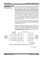
Set switch SW1 on the module to the binary equivalent of the
address. Switches 1 to 4 are used to set the module address, with
switch 4 the least significant bit, and switch 1 the most significant.
The OFF positions for SW1 correspond to binary 0, and ON
positions correspond to binary 1. Addresses in the range 1 to 12
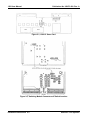
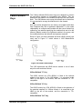
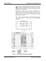
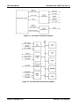
are permitted. Refer to Figure 2-2 for the location of SW1 on the
switching module PCB, or to Figure 2-3 for the location of SW1 on
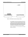
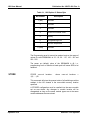
the 1260-40. The functions of the various S1 switches are shown
in Figure 2-4.
Figure 2-4, S1 Switch Function
NOTE
The address set at switch SW1 on the switching
module controls the value of the card address the
switching module will respond to. The OPEN and
CLOSE statements using the card address are
specified in Section 4.4. Example: For a module to
respond to the command CLOSE 5.1205, the address
of the module must be set to 5.
Several modules are capable of more than one configuration, and
respond to different command codes in their various
configurations. Switches 5 and 6 on SW1 are used to select the
command code sets these modules respond to. Refer to the
module specific sections for the procedure to set the switches for
each module.
For the 1260-40 only, replace the switching module covers.
Replacement is the reverse of the removal procedure.
Astronics Test Systems
Installation Instructions 2-5