1
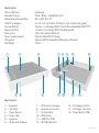
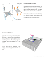
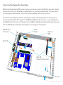
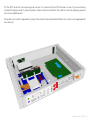
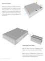
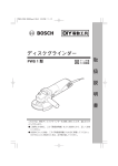
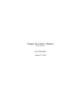
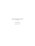
Page
2.................
3.................
4.................
5-6.............
7-8.............
9.................
10...............
11...............
12-13.........
14..............
15..............
Index, Foreword
Product Overview
Preparing for Assembly
Installing the Motherboard
Installing the CPU Cooler
Installing PSU & Other Accessories
Wiring Diagram
Installing Hard Drives
Installing PCI Card (Optional)
Replacing the Top Panel
Notes
Foreword
Thank you for your purchase of this Streacom product, every care has been taken to
ensure that it meets with the high standards that we have set for ourselves.
Should you have any questions that are not covered in this user guide, support can be
offered via email through our website at www.streacom.com
We sincerely hope that you enjoy using our product!
P2 - INDEX
Specification
Chassis Material
Available Colours
Motherboard Compatibility
HDD Drive Support
Cooling Method
Expansion Ports
Dimensions
Power Supply Support
IR Solution
Net Weight
2
1
3
4
Aluminum
Silver / Black - Sandblast Finish
Micro ATX, Mini ITX
4 x 2.5" or 3 x 3.5"(Mini ITX Only) or mix of both (see guide)
Passive - 4 x Heatpipe Direct Touch (Recommended 65W TDP*)
1 x Half or Full Height (Riser Card Required)
435 × 325 × 60mm (W×D×H)
Optional NanoPSU DC power
Optional MCE Compatible IR Receiver & Remote
5.2KG
5
6
7
8
9
10
11
12
13
15
14
Key Features
1...... Heatsink
2...... Top Panel
3...... Power Button
4...... Power LED
5...... Heatsink
6...... IR Receiver Window
7...... CPU Cooler Heatpipe
8...... Heatsink Connectors
9...... IO Shield Slot
10.... CPU Cooler
11.... USB Ports PCB
12.... IR PCB (Optional)
13.... PCI Expansion Slot
14.... DC Power Jack Hole
15.... Power Button PCB
OVERVIEW - P3
Removing the Top Panel
The top panel is held in place with 4 screws, 2
each side of the case that are accessible
between the heatsink fins. Remove the screws,
slide the top panel back then upwards away
from the chassis.
Installing the I/O Shield
Locate the I/O shield that is supplied with your
motherboard and firmly push it in place.
Ensure that it clicks in place fully otherwise the
motherboard will be difficult to fit.
P4 - PREPARING FOR ASSEMBLY
Installing the Motherboard
mITX
mATX
The FC5 Evo can accommodate either a miniITX or micro-ATX motherboard. The choice of
motherboard will determine the number of
hard drives that can be installed and the
location. For mATX boards, additional standoffs
can be added to the positions shown in red.
CPU Cooler Mounting Nut
Adhesive Pad
Protective Label
Fitting the CPU Cooler Mounting Nuts
The kit includes 4 mounting nuts which should be attached to the
motherboard prior to fitting it inside the chassis. The nuts are held in
place by adhesive pads and will be required later to mount the CPU
cooler.
With the motherboard upside down, located the
4 CPU cooler mounting holes. Peel the
protective label off the mounting nuts and stick
them to the underside of the motherboard
ensuring they correctly align with the holes.
The raised rim of the nut should fit inside the
motherboard hole.
INSTALLING THE MOTHERBOARD - P5
Fitting the Motherboard
Carefully lower the motherboard into the chassis,
with the I/O port side leading so that the ports can fit
into the I/O shield.
When the motherboard is correctly in position, fix it
to the chassis stand-offs using the screws provided.
Ensure that all the holes correctly align before fully
tightening the screws.
Upper CPU Mount
®
®
(Intel or AMD type)
Heatsink Connector
Blocks
CPU Cooler Overview
The passive CPU cooler comprises of 3 main
parts. The CPU mount which fixes to the CPU &
motherboard, the heat pipes that transfer the
heat, and the heatsink connector blocks that fix
the heatpipes to the chassis side panel
(heatsink).
In order to ensure efficient heat transfer,
thermal paste should be applied to the
surfaces shown. Do not apply the thermal paste
until the parts are ready to be installed.
Lower CPU Mount
P4 - INSTALLING THE MOTHERBOARD
Heat Pipes
®
AMD Mount
Assemble the Upper CPU Mount
Depending on which type of motherboard and
CPU socket you have purchased, you will either
need to assemble the Intel® or AMD® type upper
CPU mount. You do not need to assemble both.
The mount is assembled as shown with the long
CPU retention screws, springs and C clips
attached to the outer arms of the mount..
Intel® Mount
Affix the Lower CPU Mount
Apply a thin and even layer of thermal paste to
the surface of the CPU then carefully position
the lower CPU mount onto the CPU ensuring it
is centrally located. The heatpipe grooves
should be facing in the direction of the
heatsink.
Thermal paste can also be applied to the
heatpipe grooves in perpetration for the next
step.
INSTALLING THE CPU COOLER - P7
Installing the CPU Cooler Assembly
1. Attach the heatsink connector blocks and heatpipes to the chassis. We recommend fitting one side at a
time (pairs of heatpipes). Secure the connector blocks with screws ensuring the heatpipes align and sit
accurately in the grooves of the lower CPU connector. Do not fully tighten the screws.
2. With all 4 heatpipes attached, position the upper CPU connector onto the lower CPU connector,
sandwiching the heatpipes between them and secure upper and lower parts together using the HEX
screws and allen key supplied. Do not fully tighten the screws.
3. Ensuring the 4 spring loaded screws correctly align with the CPU cooler mounting nuts (you installed
earlier under the motherboard), carefully tighten each screw (one turn each side, alternating sides) until
fully secured. You can now fully tighten all the screws.
2
1B
1A
Warning! Do not forget to use
thermal paste, as this can result
in poor heat transfer and
eventual CPU damage.
P8 - INSTALLING THE CPU COOLER
Connect the PSU, Optional IR & Other Cables
With the motherboard and CPU cooler in place, you can now connect the PSU and any other internal
connections such as the SATA cables in perpetration for installing the hard drives. For more details
on installing the PSU and IRRC, see the user guides supplied with those accessories.
Connect the front USB ports and the power button switch to the motherboard. As the majority of
current motherboard do NOT support an INTERNAL USB3.0 header, this case is only supplied with
the USB2.0 cable. Customers that do purchase a USB3.0 compatible motherboard must purchase the
internal USB3.0 cable separately. See diagram on next page for wiring details.
USB2.0 & 3.0
Connectors
Power
Button
Optional
IRRC
Nano150
Nano180
(2 Mounting Positions)
DC Jack
INSTALLING PSU & CABLES - P9
USB 2.0 Connector
Motherboard
USB
USB 3.0 Connector
USB 2.0 Cable x 2
GND
D+
D+5V
GND
D+
D+5V
USB
NC/SHIELD
GND
D+
D+5V
WARNING: Never connect USB 2
& USB 3 cables at the same time.
USB 3.0 Connector
Front USB Ports PCB
HDD+
HDDRESET1
RESET1
NC
USB 3.0 Cable (Sold Separately)
LED+
LEDPWS2
PWS2
LED+
LEDPWS1
PWS1
Chassis Power Switch PCB
Cable colours shown are for illustrative purposes only, actual colours will vary.
P10 - WIRING DIAGRAM
Installing the Hard Drives
The FC5 Evo has 7 drive mounting areas which are available depending on which size motherboard is
fitted. Additionally, the total number of drives that can be installed will depend on which size hard drive is
being installed, 2.5" (shown in purple) or 3.5" (shown in blue). Areas that have overlap indicated that
either a 3.5" or 2.5" can be installed, but not both at the same time and drives marked ‘ITX ONLY, can only
be used when an ITX board is fitted. Drive are fitted by screwing them to the bottom panel from
underneath. Rubber pads are supplied and should be fitted to the mounting holes prior to fitting the
drives.
2
ITX ONLY
1
ITX ONLY
3
7
5
6
4
ITX ONLY
7
7
5
5
3
6
4
3
7
5
4
4
7
2
2
5
6
1B
1A
1C
3
3
6
1A
1C
1C
6
4
1C
2
2
1A
1B
1B
1A
1B
INSTALLING HARD DRIVES - P11
Installing PCI Card (Optional)
The FC5 Evo can accept either a half height or full height expansion card. When installing a half height
card, you only need to remove the low profile blanking plate (A). When installing a full height card, remove
both blanking plates and the low profile support (A+B)
A
B
B
B
Low Profile Support
P12 - INSTALLING THE PCI CARD
Fit the PCI card into the opening and secure it in place with the PCI bracket screw. If you are having
trouble fitting the card, try removing the screws shown in red. After the card fits into the opening, replace
the screws and bracket.
A flexible riser card is required to connect the card to the motherboard (the riser card is not supplied with
the chassis)
INSTALLING PCI CARD - P13
Replace the Top Panel
With all the components installed, the chassis
can now be closed. Prior to doing this, ensure
that all cables are connected and all
components are securely fitted. Replace the
top panel and secure it in place using 4 screws,
2 from either side of the case, between the
heatsink fins.
Connect Power & Other Cables
With the chassis now fully assembled, all that
remains is to connect the power and other cables.
When choosing a suitable place to position your
chassis, please consider an area with adequate air
flow and a moderate room temperature.
P14 - REPLACING THE TOP PANEL
NOTES - P15
Melbournestraat 56,
3047 BJ Rotterdam,
The Netherlands
www.streacom.com
V1.12.08