1
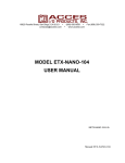
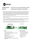
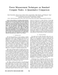
Page
2.................
3.................
4.................
5 - 6 ...........
7.................
8.................
9.................
Index, Foreword
Product Overview
Preparation for Assembly
Installing the Motherboard
Installing the CPU Cooler
Fitting the HDD/ODD
Installing the HDD/ODD Cage and Top Panel
Foreword
Thank you for your purchase of this Streacom product, every care has been taken to
ensure that it meets with the high standards that we have set for ourselves.
Should you have any questions that are not covered in this user guide, support can be
offered via email through our website at www.streacom.com
We sincerely hope that you enjoy using our product!
P2 - INDEX
Specification
Chassis Material
Available Colours
Motherboard Compatibility
HDD Drive Support
ODD Drive Support
Cooling Method
Front Ports
Dimensions
Power Supply Support
IR Solution
Net Weight
2
3
1
4
Aluminum
Silver / Black - Brushed Finish
Mini ITX
1 x 3.5" + 1 x 2.5"
Slot loading drive, left side eject button
Passive - Heat Pipe (65W Max TDH Recommended)
2 x USB, 1 x SD Card Reader
240 × 250 × 100mm (L×W×H)
Optional PicoPSU DC power
Optional MCE Compatible IR Receiver & Remote
2.6KG
5
6
10 11
9
7
8
12
13
16
14
17 18
15
Key Features
1...... Power Button
2...... Power LED
3...... ODD Eject Button
4...... ODD Loading Slot
5...... Top Panel
6...... USB Ports
7...... SD Card Reader
8...... IR Receiver Window
9...... Heat Sink
10.... Heatsink Connector
11.... CPU Cooler Heatpipe
12.... DC Power Jack Hole
13.... IO Shield Slot
14.... eSata Slots (Optional)
15.... PCI Slot
16.... USB/SD Card PCB
17.... HDD/ODD Cage
18.... Power Button PCB
OVERVIEW - P3
Removing the Top Panel
The top panel is held in place with 4 screws, 2 at
the bottom and 2 at the side. The side screws are
accessed between the gaps of the heatsink fins.
Remove the screws and slide the top panel away
from the chassis
Removing the HDD/ODD Cage
The HDD/ODD cage is held in place by 4 screws
which are all accessible from the top as shown.
Once all 4 screws are removed, slide the cage
out of the chassis.
Removing the CPU Cooler
The heat pipes are connected to the chassis
using 2 connector blocks which are held in place
with a total of 8 screws (4 for each block).
Unscrew all 8 screws which are accessible via
the gaps in between the heatsink fins.
P4 - PREPARING FOR ASSEMBLY
Installing the I/O Shield
Locate the I/O shield that is supplied with your
motherboard and firmly push it in place. Ensure that it
clicks in place fully otherwise the motherboard will be
difficult to fit.
CPU Cooler Mounting Nut
Adhesive Pad
Protective Label
Fit the CPU Cooler Mounting Nuts
The chassis is supplied with 4 mounting nuts
which should be fixed to the motherboard prior to
fitting it. The nuts should be fixed to the underside
of the motherboard and are held in place by
adhesive pads.
With the motherboard upside down, located the 4
CPU cooler mounting holes. Peel the protective
label off the mounting nuts and stick them to the
underside of the motherboard ensuring they
correctly align with the holes.
INSTALLING THE MOTHERBOARD - P5
Installing the Motherboard
Carefully lower the motherboard into the chassis, with the
I/O port side leading so that the ports can fit into the I/O
shield.
When the motherboard is correctly in position, fix it to the
chassis stand-offs using the screws provided. Ensure that all
the holes correctly align before fully tightening the screws.
Connect PicoPSU & Other Cables
With the motherboard in place, you can now connect the
PSU and any other internal connectors such as the power
button switch. You should also connect the SATA cables in
perpetration for installing the HDD/ODD cage assembly.
Heatsink Connector
Blocks
CPU Cooler Overview
The passive CPU cooler comprises of 3 main parts.
The CPU cooler which fixes to the CPU, the heat
pipes that transfer the heat, and the heatsink
connector blocks that fix the heatpipes to the chassis
side panel (heatsink). In order to ensure efficient
heat transfer, thermal paste should be applied to the
surfaces shown. Do not apply the thermal paste until
the parts are ready to be installed.
Upper CPU
Cooler
Heat Pipes
Lower CPU
Cooler
P6 - INSTALLING THE MOTHERBOARD
Attach the CPU Cooler Retention Arms
The kit will include 2 retention arms which should be fixed
to the underside of the lower CPU connector. These arms
will allow the cooler to be fixed to the CPU and
Motherboard. Thermal paste should be applied to the
surface that will be in contact with the CPU. The arms are
held in place by 4 screws.
Place the lower CPU cooler onto the CPU ensuring the
holes of the mounting arms align with the 4 mounting nuts
that were previously fixed to the motherboard. Install all 4
screws and gradually tighten each one so that equal
pressure is applied to each corner until all 4 are fully
secured.
With the lower CPU Cooler now fixed in place, ensure
that thermal paste is applied to all the specified areas
and fit the upper CPU cooler, heatpipes and heatsink
connector blocks in place. The upper CPU cooler is held
in place by 4 screws and the heatsink connectors are
help in place by a total of 8 screws, 4 for each side. The
heatpipes, connectors and cooler are designed to have
an adjustable position which allows for different
motherboard CPU locations.
INSTALLING THE CPU COOLER - P7
Installing the HD and OD Drives
With the cage out of the chassis, all the drives
can fitted with ease.
3
The slot loading optical drive is mounted using
4 screws, 2 either side. The mounting holes
are rectangular which allows for small
adjustments to the position on the drive. This
is useful when adjusting the proximity to the
chassis eject button.
3
3
1
3
3
1
2
1
1
1
2
The 3.5" hard drive fits under the optical drive
and has 4 rubber dampeners to reduce noise
from hard drive vibrations.
2
2
2
The 2.5" hard drive can be mounted behind the
optical drive and is secured underneath with 4
screws.
Fitting the Eject Button and HDD/ODD Cage
Prior to replacing the HDD/ODD cage into the
chassis, the ODD eject button should be
fitted. The eject button is packed with the
other screws and accessories and simply fits
as shown into the hole below the ODD slot.
The cage can now be replaced into the
chassis. Carefully slide the assembly
ensuring cables are routed correctly and that
the ODD eject button aligns and is held in
place by the optical drive. The cage is
secured by 4 screws from above.
P8 - FITTING THE HDD & ODD
Installing PCI Card (Optional)
To install an expansion card, first remove the pre-installed
PCI blanking plate by removing the single lower screw. The
PCI mount can also be removed to make it easier to install
the expansion card. This is done by removing the 2 screws
either side on the mount.
Carefully place the card into the motherboard slot ensuring
the rear side (where the ports are located) firstly passes
through the expansion slot opening of the chassis. Once the
card is fully seated into the motherboard, replace the PCI
mount and finally secure the card with the single screw
from underneath the mount.
Replace the Top Panel
With all the components installed, all that remains is to
replace the top panel. Prior to doing this, ensure that all
cables are connected and all components are securely
fitted. Replace the top panel and secure it in place using 4
screws, 2 from the side and 2 from underneath the chassis.
INSTALLING PCI CARD AND TOP PANEL - P9
Melbournestraat 56,
3047 BJ Rotterdam,
The Netherlands
www.streacom.com
V1.12.02