1
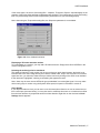
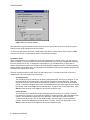
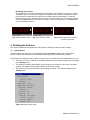
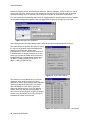
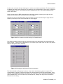
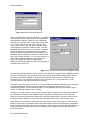
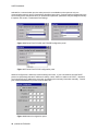
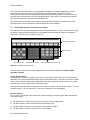
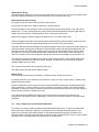
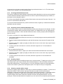
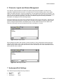
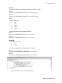
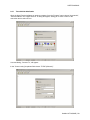
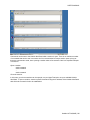
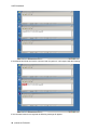
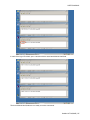
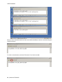
USER’S MANUAL
Table of Contents
1
Kaleido-Alto and Kaleido-Quad User’s Manual...................................................................... 1
1.1
1.2
2
Kaleido-Alto/Quad System Concepts ..................................................................................... 2
2.1
2.2
3
Quick Tour of the System ................................................................................................................... 3
The Toolbar......................................................................................................................................... 3
Using a Layout .................................................................................................................................... 5
Detailing the Features.............................................................................................................. 9
4.1
4.2
5
Software Components ........................................................................................................................ 2
Visual Elements .................................................................................................................................. 2
Getting Started with the Kaleido-Alto/Quad ........................................................................... 3
3.1
3.2
3.3
4
Introduction ......................................................................................................................................... 1
Installation and Connection................................................................................................................. 1
System Status ..................................................................................................................................... 9
Parameter Settings ........................................................................................................................... 11
Controlling Kaleido-Alto/Quad Using the Kaleido-RCP or a Keyboard .............................. 17
5.1
5.2
5.3
Kaleido-RCP Remote Control Panel Description.............................................................................. 18
Using a keyboard to control Kaleido-Alto/Quad................................................................................ 19
Kaleido-RCP operation in detail........................................................................................................ 20
5.3.1 Accessing a single Kaleido-Alto/Quad using the Kaleido-RCP ........................................... 20
5.3.2 Accessing all Kaleido-Alto/Quad units using the Kaleido-RCP ........................................... 20
5.3.3 Accessing Kaleido-Alto/Quad units...................................................................................... 21
5.3.4 Restricting Control of Kaleido-Alto/Quad units .................................................................... 21
5.3.5 Recalling a layout................................................................................................................. 21
5.3.6 Selecting a monitor within a layout ...................................................................................... 21
5.3.7 Assigning a channel to a monitor......................................................................................... 22
5.3.8 Changing the video screen aspect ratio within a monitor .................................................... 22
5.3.9 Audio monitoring .................................................................................................................. 22
5.3.10 Full screen display ............................................................................................................... 22
5.3.11 Resetting the Kaleido-RCP .................................................................................................. 22
6
7
Channels, Layouts and Alarms Management ...................................................................... 23
Andromeda Port Settings ...................................................................................................... 23
8
Using XML commands with the Kaleido-Alto/Quad............................................................. 26
8.1
8.2
Commands........................................................................................................................................ 27
A typical session ............................................................................................................................... 29
8.2.1 Three Kaleido-Alto/Quads.................................................................................................... 33
Kaleido-ALTO/QUAD
USER’S MANUAL
2 Kaleido-Alto/Quad System Concepts
2.1
Software Components
There are two software components associated with the Kaleido-Alto/Quad system:
•
•
Kaleido-Alto/Quad software is already installed in the Kaleido-Alto/Quad unit, and performs all
functions associated with integrating data streams and presenting the multi-image display.
K-Edit Layout Editor software runs on a remote computer connected to the Kaleido-Alto or
Kaleido-Quad through an IP interface. It creates the on-screen layout formats used by the
Kaleido-Alto/Quad.
2.2 Visual Elements
Kaleido-Alto/Quad replaces the traditional physical display devices in a monitor wall, such as video
monitors, audio meters and tally lamps, with graphical representations. The objects and images that
appear on the screen of the Kaleido-Alto/Quad multi-image display and of the computer running KaleidoEdit Layout Editor will be referred to as visual elements. A visual element is the on-screen manifestation
of a data stream.
There is a one-to-one correspondence between the visual elements in a layout prepared in K-Edit Layout
Editor, and those presented on the Kaleido-Alto/Quad multi-image display.
However, there is an essential difference between the visual elements as presented by these two
packages:
•
•
The multi-image output represents the exact program stream being processed. Its visual elements
show a dynamic, real-time representation of the data in the program stream. UMDs, status and tally
indicators change shape and color according to the information status. All objects are drawn with
details and resolution. Text appears with a cleanly rendered font
The K-Edit Layout Editor software is used off-line to create the elements to be used in the actual
Kaleido-Alto/Quad multi-image display output. As such, it has no knowledge of the actual information
that the Kaleido-Alto/Quad is processing. The Kaleido-Edit Layout Editor representation is static, and
the visual elements are displayed as icons, of the correct size and position, but without dynamic
program content.
While the K-Edit Layout Editor screen shows a good representation of the final output, the user is advised
to look at the actual Kaleido-Alto/Quad output on the monitor wall screen, to assure themselves that the
output is as desired.
This manual describes operation of the Kaleido-Alto/Quad. The use of the K-Edit software to create
layouts for the Kaleido-Alto/Quad is described in its own manual, which is available as on-line help when
you are running the K-Edit software.
2 | Kaleido-ALTO/QUAD
USER’S MANUAL
3 Getting Started with the Kaleido-Alto/Quad
3.1 Quick Tour of the System
Once the Kaleido-Alto/Quad is properly set up and powered, it provides immediately a multi-image output.
A default layout is used to monitor the incoming feeds. Figure 3.1 below shows the principal features of a
layout .
Figure 3.1 Kaleido-Alto layout
The first thing that you notice is the visual elements: there are several windows with UMD information
underneath, VU meters, clock, tallies, even countdown timers (not shown in this figure). All these
elements may be configured to suit your monitoring preferences, as explained in the following sections.
In addition, when the mouse is moved toward the bottom of the screen, a toolbar appears, with buttons
and icons. The layout buttons are used to quickly change the layout being displayed. The K-Alto or KQuad button gives access to different system-level parameters, and the icon buttons are tools to
customize the windows and layouts. When using a Kaleido-RCP, the buttons of the remote panel allow
much of the same control and flexibility as if you were accessing the task bar with a mouse.
3.2 The Toolbar
Just like a PC computer, moving the mouse toward the bottom of the screen calls up the toolbar. This bar
is composed of buttons, detailed in the image below.
Kaleido-ALTO/QUAD | 3
USER’S MANUAL
Figure 3.2 Elements of the toolbar
The K-Alto or K-Quad button contains a sub-menu showing the system parameters settings and status
information; they will be described in detail in section 4.
The Software Input Panel (SIP) Button
To access this tool, click the keycap icon in the toolbar and the SIP keyboard will appear in the bottom
right corner of the screen. Using the mouse to click keycaps, you will find that it reacts just like a physical
keyboard. To move this panel, just click on its title bar, hold and move the mouse, and release the left
button on the mouse.
Figure 3.3 SIP Keyboard
The Volume control button controls the volume of the channel being monitored. When pushed, a long
slider appears, with 3 additional buttons. Moving the slider changes the volume as expected; the “Mute”
button mutes the volume and the “-20dB” attenuates it accordingly. Use the ”Select” button to specify
which audio group to monitor for each channel, in the case of embedded audio. This feature will be
detailed in section 4. If the volume is being changed using the RCP or keyboard, this volume control will
appear, and can be used to monitor the changes as the are made.
Figure 3.4 Volume Control
Open File and Save File buttons allows access to the internal memory of the Kaleido-Alto/Quad, in which
is stored channel information and layouts.
The Layout Selection buttons enable the quick change of layouts. There are 20 layouts saved by
defaults on the Kaleido-Alto/Quad; ten buttons are visible at once on the tool bar, to access the next ten
click the “Shift” button. The first ten defaults layouts are for a 16:9 display, the layouts 11 to 20 are for a
4:3 display. You can rename a layout by right-clicking on the button and selecting Rename Recall Button;
the button turns in editing mode and a new name can be entered.
4 | Kaleido-ALTO/QUAD
USER’S MANUAL
3.3 Using a Layout
In this section you will learn how to “use” the layout and understand the different parameters associated
with the video images. Each window in the layout, with a video screen coupled with audio and data
information, is called a “monitor”.
To personalize your layout, you will use the mouse supplied with the unit; there is a lot you can do just by
doing what you would normally do with a computer. Note that you do not need a physical keyboard to
enter text, the software input panel (SIP) built-in in the software will be used for that purpose.
If you already have inputs connected to your unit, they will display right away in the monitors. Each
monitor is configured to include a video image, an audio signal and data information; this grouping of
signals and data is called a channel, and may be changed using K-Edit. Several channel configurations
may be saved inside Kaleido-Alto/Quad, as explained later. A channel may be placed in any window of
the layout; the window may be assigned a name, its aspect ratio may be changed, markers may be
displayed, etc. We will detail these below.
Note: To better explain the difference between Monitors and Channels, let’s use the following
example:
-A Monitor is analogous to a common home TV set: it has a screen, speakers, possibly the option to
display the closed captioning (CC), and some on-screen text to identify the current program.
-A Channel is conceptually the same as a broadcast or cable channel (which includes video, audio,
closed captioning text, program information, etc) captured by the TV set. Assigning a channel to a
Kaleido-Alto/Quad monitor is equivalent to switching a TV set to a numbered channel.
Editing Text ID
Click on the monitor’s text ID bar and it immediately turns in Edit mode – the text ID is highlighted and
ready to be overwritten. To change the text, you need to use the keyboard – either a physical, USB
keyboard connected to the unit or the SIP keyboard. Note that you need to click the SIP keyboard first,
then select the name bar. Whether you use the SIP keyboard or a physical one, you need to push the
Enter key to validate the new text ID or the ESC key to exit without change.
Note: if you change layouts, the text ID will disappear. If you wish to associate the new ID with the
channel, you need to save it using the Save File button. Saving it will ensure that the channel stays with
the new name throughout all the layouts.
Assigning a new channel to a monitor
Right-clicking on a window brings up the monitor configuration menu. The first item of this menu is
Assignment. Select Assignment to display the Channel Selection as shown on image below. The
current Channel Assignment for this window is grayed out. Select any channel to be displayed in the
monitor; a channel may be assigned to more than one monitor, but the actual input signal will only be
visible in the last monitor assignment.
Figure 3.5 Channel Selection
Kaleido-ALTO/QUAD | 5
USER’S MANUAL
Note: you can see at a glance which channel is assigned to which monitor by clicking the Tab key on the
SIP keyboard (you can do this also with the Kaleido-RCP – more on that in section 5).
Making a monitor display full screen
The next parameter in the Monitor Configuration menu is Full Screen, which makes the window fill up the
screen. When a monitor has been enlarged to full screen, right-click on it and you will notice that a check
mark appears next to the Full Screen parameter; select Full Screen again to unselect it, and the
previous layout is restored.
Note: the full screen layout is configurable via K-Edit (see section 7 K-Edit Software ) and can be saved
as default by pressing the Full Screen key on the Kaleido-RCP for more than 7 seconds (see section 5.3
Kaleido-RCP operation in details).
Changing a monitor’s aspect ratio
If the video input signal is of a different aspect ratio than the monitor in which it is displayed, you may
change the monitor’s aspect ratio to display the signal without deformation. The available selections are
4:3, 16:9, and a custom ratio if any, defined with K-Edit (i.e. 14:9).
Figure 3.6 Aspect Ratio Selection
Displaying an underscan video signal
During normal operation, the entire video field of the video input signal in displayed within the monitor;
checking Underscan will display only the visible field.
Displaying aspect ratio markers in a monitor
You may display markers in a monitor to show how a 4:3 input signal will display in 16:9 or vice-versa.
Select Markers… in the monitor configuration menu to display the markers menu. Check the box to
display markers in the format that you wish to monitor your monitor. You can also check the two boxes to
display markers all the times when changing the monitor’s aspect ratio. Click the OK button to apply your
selection.
Figure 3.7 Markers Display Selection
Calibrating a video signal
For monitoring purpose, you may want to modify the input signal calibration. Select Calibration… to
display the Video Calibration menu. You can adjust the Brightness, Contrast, Hue, Color and Sharpness
parameters directly by using the sliders. To reset the signal to “factory” calibration click Default. Click the
Custom button to apply your calibration to the video. A built-in DeInterlacer may also improve the display
6 | Kaleido-ALTO/QUAD
USER’S MANUAL
of the video signal; the choice of decoding filter - Adaptive, Temporal or Spatial – depends highly on the
contents of the image. Most artifacts will disappear with Adaptive. The simplest way to select a decoding
filter is to pass through each one and compare their performances on your monitoring display.
Note: when using the Temporal decoding filter, the Sharpness parameter is not available.
Figure 3.8 Video Calibration window
Displaying a 3D border around a monitor
To put emphasis on a monitor, you may add a 3D frame around it. Simply select Show 3D Effect in the
monitor configuration menu.
Selecting the audio signal to be monitored
The assigned channel in each monitor may or may not have an audio signal present; the Audio Level
indicator next to the video image shows you if there is indeed audio. As you can only listen to one audio
signal at a time, you select the channel that you wish to monitor by clicking on the Audio Level indicator.
It then becomes “highlighted”, showing a contrasting line appears around it.
Note: there may be more several AES audio group embedded in a serial digital signal. You may select
which audio group to monitor using the System Status panel; this panel is described in section 4.
Clock display
If your layout includes a clock, you can set it to use its internal time reference or use an external source
from a serial port (see note below). You may also set it to a different time zone or to include a time offset
from the time reference by a specified amount in either direction. Right-click on the clock and a Clock
Settings window appears.
Kaleido-ALTO/QUAD | 7
USER’S MANUAL
Figure 3.9 Clock Settings window
Note that when using the internal reference time, the correct time of day needs to be set in the system
settings, which will be explained in the next section.
To input time code from a serial port, use Miranda’s Little Red to connect Linear Time Code (on a BNC
connector) to RS-232, as described in section 4.2 Parameters Settings.
Countdown Timer
When a countdown timer is available in a layout (see section 9.8 Countdown Timer), you may use it to
either countdown or count up a specific time interval. Additionally, you can set it to display the remaining
time to a specific time of day. To change the timer behavior (e.g. countdown time, count up time or
display remaining time) click on the top right icon; it will change to signals its function. The down pointing
arrow indicates a count down timer, a up pointing arrow indicates a count up timer and the hourglass icon
indicates the remaining time counter.
The timer provides controls to start, stop, loop and reset a timer. To access the controls, click on the
double arrow in the lower right corner of the timer.
Countdown timer:
The countdown timer is identified by its arrow pointing downward: see figure 3.10 below. To set
the time interval to count down from, click on the time display to access edit mode. Enter the
desired time interval; the seconds are entered first, up to the hours. Click Enter when finished
editing. To start the countdown timer, click on the double arrow in the lower right corner to access
the controls. Click on the Play button to start the timer. To stop it, click on the Stop button. Click
Reset to reset the timer or the Loop icon to loop the countdown cycle.
Count up timer:
The count up timer is identified by its arrow pointing upward: see figure 3.11 below. To set the
time interval to count up to, click on the time display to access edit mode. Enter the desired time
interval; the seconds are entered first, up to the hours. Click Enter when finished editing.
To start the count up timer, click on the double arrow in the lower right corner to access the
controls. Click on the Play button to start the timer. To stop it, click on the Stop button. Click
Reset to reset the timer or the Loop icon to loop the countdown cycle.
8 | Kaleido-ALTO/QUAD
USER’S MANUAL
Remaining time counter:
The remaining time counter is identified by the hourglass icon: see figure 3.12 below. To set the
“destination” time, click on the time display to access edit mode. Enter the desired time of day;
the seconds are entered first, up to the hours.Click Enter when finished editing. To start the
remaining time counter, click on the double arrow in the lower right corner to access the controls.
Click on the Play button to start the timer. To stop it, click on the Stop button. The Reset button
is not used with this function.
Fig. 3.10 Countdown Timer
Fig. 3.11 Count Up Timer
Fig. 3.12 Remaining Time Counter
(Controls not shown)
4 Detailing the Features
This section will detail all the parameters of the system, including all video and audio settings.
4.1 System Status
From the toolbar click the K-Alto or K-Quad button and select Status to display the System Status
window. This window includes four tab-selectable panels that give information on the system.
The first panel is the System status, shown on figure below. It contains basic information about your unit.
•
The name of the unit, its adress, IP and MAC addresses (some of these settings may be changed
in the Settings menu).
•
The Software, firmware and hardware version numbers are indicated. In the event of a system
upgrade, the software and firmware numbers will reflect the change.
•
The RS-232, RS-422 A and RS-422 B ports settings are listed. They may be changed in the
Settings menu.
Figure 4.1 System status panel
Kaleido-ALTO/QUAD | 9
USER’S MANUAL
The next panel is the Video status. Listed here are the type and format of all video inputs connected to
the unit, as well as the output settings currently selected. Additionally, when an embedded audio is being
monitored, the corresponding SDI input is highlighted as shown below. On figure 4.2, the panel shows a
MWO-HDM monitoring output mezzanine installed (lower right corner).
Figure 4.2 Video status panel
The Audio status panel shows all the audio that may be connected to the unit, and indicates if an optional
audio card is installed.
•
Embedded AES audio signals are listed here for each valid SDI input: there may be up to four
audio groups per input, each consisting of 2 signal pairs (or four signals).
Note: in this panel you may also select which audio signal to monitor by clicking on a pair. The
pair selected is then highlighted and becomes audible.
•
Only one of the two audio groups are listed at a time for all the inputs; to view the other audio
groups, click on the button for the other group and they are in their turn listed below.
Audio status:
GREEN:
RED:
GRAY:
On
Silence or Overload
Disabled
Figure 4.3 Audio status panel
•
If there is an optional audio card installed in the system, the status of the audio signal connected
to the card is also shown on this panel, much the same way as embedded audio. The symbols
are grayed out if no card is installed.
10 | Kaleido-ALTO/QUAD
USER’S MANUAL
The GPI status panel lists the active GPI inputs connected to the unit, and the status of the GPI outputs..
The GPI inputs are used to activate alarms. GPI input configurations are defined with K-Edit software.
GPI Outputs are generated by Actions, and defined in KEdit.
Figure 4.4 GPI status panel
4.2
Parameter Settings
System-level settings are changed in the Settings menu. In here you configure the system to interact
with your existing installation and set some basic controls.
Figure 4.5 Settings menu
The Input Panel Properties allows changing the size of the keys on the SIP keyboard. Click Options…
and choose between Large keys and Small keys. You can also use the Use gesture… feature to
replace some keys on the keyboard such as Enter and Space. Other properties are not supported yet.
Figure 4.6 Input Panel Properties
Kaleido-ALTO/QUAD | 11
USER’S MANUAL
Date/Time is where you set the internal time reference. Start by setting the Time zone that you wish to
use for your reference. Set the date on the calendar by selecting the correct month using the left/right
arrows and clicking on the correct date; set current time using the up arrow/down arrow buttons.
You may choose the Automatically adjust clock for daylight saving to allow the system to add or subtract
an hour when daylight saving applies. Click the Apply button to apply the changes you just made.
Figure 4.7 Date/Time Properties
Audio Settings opens the Audio Settings panel, which allows various audio parameters to be set.
The Audio Meters tab provides the option of setting
the rise time of the audio meters associated with
audio from the audio card. Select either
Instantaneous or 10 ms. Note that the rise time for
Embedded audio is always instantaneous. It also
allows you to select the 0 dBU reference point for
analog monitoring of digital signals. Select either 24 dBFS = 0 dBU (per SMPTE RP-155) or -18
dBFS = 0 dBU (per EBU RP-68).
Figure 4. 8 Audio meter settings
The Audio Error Config tab allows you to set the
conditions under which an audio error will be
detected for each of the embedded audio channels
entering the Kaleido-ALTO/QUAD. This can be
done individually for each channel (select the
channel by selecting Group 1-2 or 3-4 using the
buttons at the top, and then selecting AES 1 or
AES 2 for one of the 10 inputs using the 40 buttons
below), or for all channels at once (by clicking the
Embedded Gr. Button at the top left).
Figure 4.9 Audio Error Configuration – main panel
12 | Kaleido-ALTO/QUAD
USER’S MANUAL
In either case, a window will open allowing you to set the error detection parameters. The window header
will identify the specific audio channel you are setting up (in the example below: Video input 1, AES group
1, AES Channel 1) or ALL if you selected to set up all channels at once. The window contents are the
same in both cases:
Silence: set the level (in dBFS) below which the signal must remain continuously for longer than the
duration (in seconds) in order for a Silence error to be flagged.
Overload: set the level (in dBFS) above which the signal must remain continuously for longer than the
duration (in seconds) in order for an Overload error to be flagged.
Figure 4.10 Error detection threshold settings for Embedded audio
The Analog Gain tab provides a slider for each of the inputs of the analog audio card, allowing the gain
levels to be set. The gain can be adjusted from 0 to 30 dB in steps of 6 dB. (Note: this tab is only present
when an analog audio card is installed)
Figure 4.11 Analog gain adjustment for the input channels.
The Kaleido-Alto/Quad ID property is where a unique name and address is given to a system. This
unique address is used by a remote control panel or other equipment for RS-422 communication. As an
example, several Kaleido-Alto/Quads, each with its own ID number, may be controlled individually by the
optional Kaleido-RCP. The unit’s name may be changed also, although the utility of this information is
limited for the time being.
Kaleido-ALTO/QUAD | 13
USER’S MANUAL
Figure 4.12 Kaleido-Alto/Quad ID panel
Output Configuration must be set according to your display
device (plasma monitor, video projector, etc.) capabilities
and installation conditions. Select the correct Resolution
and frequency in the list: 1920 x 1080, 1600 x 1200, 1024
x 768, 1280 x 1024, 1280 x 768, 1360 x 768 and 800 x
600, all at 50 or 60 Hz. (NB: the 1920 x 1080 and 1600 x
1200 images are presented in letterbox format – see the
installation manual for details). You may have to manually
change the resolution on the display device if it doesn’t
lock on the Kaleido-Alto/Quad’s output automatically. The
RGB Gain may be changed to increase the video dynamic
range; some display accepts 1.0 V. p.p. while others not. A
built-in cable equalization allow to compensate for the
output cable length; try the different cable length
categories (Short Cable, Medium Cable and Long Cable) if
the signal seems to be noisy.
Figure 4.13 Output Configuration panel, RGB/DVI Output
An optional monitoring mezzanine can be installed in the Alto/Quad to convert its main RGB/DVI output to
an SD or HD SDI format. Two mezzanine models are available: MWO-SDM and MWO-HDM. When a
monitoring mezzanine is installed, an additional tab named SDI Output provides controls over the
monitoring output. The monitoring mezzanine may be used as a 10 x 1 routing switcher or a scan
converter, and may also output a test signal (color bars).
As shown on the left of figure 4.14, the 10 x 1 Routing Switcher is selected; when this option is selected,
any of the Alto/Quad’s 10 inputs may be directed at the monitoring output by clicking on the
corresponding window. This is particularly useful for a QC application where any of the inputs may be
viewed on a Waveform Monitor, as an example.
As shown on the right of figure 4.14, the Scan Converter option is selected; when this option is selected,
the mezzanine converts the main RGB/DVI output of the Kaleido-Alto/Quad into an HD or SD video
signal. A pull-down list displays the available HD or SD SDI output formats. A checkbox allows to retain
the original output’s aspect ratio, in the case where the display device is of a different aspect ratio.
Detail Enhancer and Sharpness sliders allow the user to select a value in the range 0 to 16, 8 being the
default (nominal) value in all output formats. The Detail Enhancer increases high frequency components
thereby increasing fine detail and edges. The Sharpness slider allows to choose an aliasing adjustment, 0
being maximum anti-aliasing and 16 maximum aliasing (or max. sharpness), resulting in more or less
perceived flickering.
14 | Kaleido-ALTO/QUAD
USER’S MANUAL
You may also choose to output a color bars test pattern at the MWO-HDM or MWO-SDM output: check
the Color Bars checkbox.
Figure 4.14 Output Configuration panel, SDI Output
The PowerUp menu item opens up the Save Default Layout window; clicking the button saves the
position of each window in hardware as system default, which will be used when powering up. This layout
will appear after 5 seconds when power up is initiated. Current layout is re-applied once the application is
up and running (10 sec. later).
Figure 4.15 PowerUp panel
The Volume item menu invokes the same volume control slider described on page 6.
Serial Ports configuration is achieved through this control panel and enables each communication port.
They may be used to communicate with third-party devices to provide tally information and dynamic text
for UMDs and Text Labels or interface with the Kaleido-RCP or a time code reader such as Miranda’s
Little Red. Details on how to use the data can be found in the K-Edit software’s on-line help manual.
Assign a function to each port as needed. When using a Kaleido-RCP with the unit, select the KaleidoRCP option in the menu for Port RS-422 A. When using a Little Red Time Code Reader, select TC in
Little Red for Port RS-232. Note that TSL and Andromeda protocols are mutually exclusive; when one is
Kaleido-ALTO/QUAD | 15
USER’S MANUAL
selected for a communication port, the other protocol is not available on other ports as only one
communication protocol may be used with the Alto/Quad at any time. Communication port parameters are
set according to the selected function; for Andromeda in particular, parameters may be changed manually
if required. See section 7 Andromeda Port Settings.
Figure 4.16 Serial Ports RS-422A and RS-422B configuration panel
Figure 4.17 Serial Ports RS-232 configuration panel
Network Configuration is where the network settings are found. If your LAN network uses the DHCP
protocol to dynamically allocate IP address on startup, check “Obtain an address via DHCP”; otherwise,
you must specify an IP address the usual way, by entering the necessary information manually. Consult
your network administrator if you are not sure about this.
Figure 4.18 Network configuration panel
16 | Kaleido-ALTO/QUAD
USER’S MANUAL
Disable Actions opens the Action Settings window, showing the Actions Enabled checkbox. Unchecking
this box disables all actions on the Kaleido ALTO/QUAD. This is of most use when a sequence of actions
is inadvertently triggered that enters a loop. The only way to get out of the loop is to disable actions using
this panel, and then examine the sequence of actions and eliminate the problem.
Figure 4.19 Action Settings panel
Mouse Configuration sets the time duration since the last mouse movement after which the mouse cursor
will become invisible on the screen. The cursor will immediately become visible again if the mouse is
moved.
Figure 4.20 Mouse configuration panel
Options opens a window that allows the user to activate the Embedded Audio option on the Kaleido
ALTO/QUAD. If you wish to purchase this option, contact your sales representative. Once the option is
purchased, you will be sent a key that is exclusive to your Kaleido (i.e. based on the serial number). Enter
the key in the Embedded Audio data box, and click the Validate button in the lower right of the window.
Once the key is validated, the Validate button will be replaced by a Save button. Click it to store the valid
key information in the system. The option is now activated.
Figure 4.21 Network configuration panel
5 Controlling Kaleido-Alto/Quad Using the Kaleido-RCP or a
Keyboard
The Kaleido-Alto/Quad may be controlled in operation using either the Kaleido-RCP remote control panel,
or a standard computer keyboard plugged into its rear panel. The Kaleido-RCP may be located far away
from the Kaleido-Alto/Quad itself, and has a keyboard designed to access Kaleido-Alto/Quad functions,
Kaleido-ALTO/QUAD | 17
USER’S MANUAL
so it will be the most useful choice in most operational situations. A computer keyboard may only be
located near the frame, but has the full functionality of the Kaleido-RCP, and may be used for
maintenance or when the frame is physically located near the operating location. For convenience, the
operation will be described here in terms of the Kaleido-RCP. See section 5.2 to identify the keyboard
keys that are equivalent to the various Kaleido-RCP keys.
The Kaleido-RCP controls allow many aspects of the multi-image display to be controlled, but some
parameters such as input calibration or markers display are not accessibles.
5.1
Kaleido-RCP Remote Control Panel Description
The Kaleido-RCP is designed specifically to operate Kaleido-Alto/Quad. It may be used to control, singly
or together, multiple Kaleido-Alto/Quad. See the Kaleido-Alto/Quad hardware manual for installation
instructions. The panel layout is shown in figure 5.1.
Layout Presets Group
Modes Group
Functions Group
Alphanumeric Group
Direct Command Access Group
Figure 5.1 Kaleido-RCP Functions
The use of these controls for operational adjustment of the Kaleido is detailed in 5.3 Kaleido-RCP
operation in details.
Layout Presets Group
In a production environment, display layouts need to be accessed quickly and easily. The Kaleido-RCP
allows the user to access stored layouts through Layout Presets buttons 1 through 10. Push one of these
buttons and the Kaleido-Allto instantly updates the layout being displayed. Above the buttons is a paper
strip that can be used to identify these customized layouts.
Note that when the Shift button is clickeded in the toolbar using the mouse, the Preset buttons 1 to 10 will
recall the layouts 11 to 20 respectively; in this case, the buttons are not highlighted.
Functions Group
The up, down, left and right arrow buttons are used for moving the selection pointer when adjusting the
multi-image output.
•
•
•
•
The Select button enables monitors to be accessed on-screen for adjustment.
The Enter button is used to add monitors to the selection group.
The Esc button allows the user to escape an action without changes.
The Menu button is inactive for this version of the software.
18 | Kaleido-ALTO/QUAD
USER’S MANUAL
Alphanumeric Group
The alphanumeric buttons are used to type text in the name bar of a monitor or to enter ID numbers when
selecting a Kaleido-Alto/Quad to control. The DELETE key is included in this group.
Direct Command Access Group
This group is used to control certain on-screen effects directly.
Input invokes the input list to assign a channel to a selected monitor.
Full Screen applies to the selected or most recently selected monitor and enlarges it until it fills up the
display area. You can cycle through all monitors having channel assignments using the Right and Left
buttons. Press Full Screen or Escape again to return to the multi-screen mode.
Aspect Ratio toggles a window’s aspect ratio between 4:3. 16:9, and a custom ratio.
Underscan toggles a window’s scan mode between Underscan/Normal and Overscan, allowing the user
to see whether the vertical and horizontal blanking areas are seen in the video window.
Audio Mon activates audio monitoring for the selected window. Audio volume may be controlled by the Up
and Down buttons; pushing the Left button will mute the audio output and pushing the Right button will
attenuate the level by 20 dB. When multiple meters are active for the selected window, pushing Audio
Mon again will cycle audio monitoring among the available pairs of audio inputs. When this feature is
used, the on-screen volume bar will appear, and can be used as a visual indicator of the volume level.
Text activates text edition for UMD and Text Label of the selected window. When multiple UMD’s and
Text Labels are present in the selected window, pushing Text again will cycle text edition among the
available UMD’s and Text Labels.
The Load and Save buttons are reserved for future use.
The Status button open the System Status window.
Modes Group
The Kaleido-RCP has 4 modes of operation: Standby, Device, All Devices and Lock.
In Standby mode, the unit is waiting for an instruction to enter one of the 3 other modes. Standby is the
default mode upon startup.
Device or All Devices modes let the user control a selected Kaleido-Alto/Quad or all Kaleido-Alto/Quad
units, respectively. In Device mode, the user is required to enter the ID number of the desired KaleidoAlto/Quad. In All Devices mode, all Kaleido frames will be controlled at the same time (only the loading of
layouts can be controlled in All Devices mode).
Lock mode effectively disables all but the Layout Presets buttons, preventing any change in the
configuration of the Kaleido frames. Additionally, it can be used to restrain access to a selected KaleidAlto/Quad.
5.2
Using a keyboard to control Kaleido-Alto/Quad
For setting up a complex system including several Kaleido-Alto/Quad units, or when the Kaleido-RCP
and/or the mouse is missing or defective, it is possible to use a standard extended keyboard. The
keyboard is connected to the USB connector on the Kaleido-Alto/Quad rear panel, as shown in the
hardware manual. Note that the functionality is identical to that of a Kaleido-RCP. Figure 5.2 below shows
the keys used on a keyboard and their equivalent on the Kaleido-RCP.
Kaleido-ALTO/QUAD | 19
USER’S MANUAL
Key
Kaleido RCP equivalent
Esc:
Tab:
Enter:
CTRL+A:
CTRL+F:
CTRL+R:
CTRL+U:
CTRL+W:
CTRL+Y:
Arrow keys:
Function keys:
Escape
Select
Enter
Input
Full Screen
Aspect Ratio
Underscan
Audio Mon
Status
Arrow buttons
Layout Presets buttons
Figure 5.2 Keyboard key assignments for Kaleido operation
5.3 Kaleido-RCP operation in detail
Using the Kaleido-RCP to operate the Kaleido-Alto/Quad is similar to using the mouse. The same menu
and windows appear for all the features; refer to section 3.3 for a specific description of all the features.
5.3.1 Accessing a single Kaleido-Alto/Quad using the Kaleido-RCP
To access a single Kaleido-Alto/Quad in a daisy-chain of several units, follow these steps:
1- Push the Device button on the Kaleido-RCP. The Device button lights up brightly (and the current
layout button if applicable) and all alphanumeric buttons light up as the unit awaits an ID number
entry. At the same time, on all display devices, the ID number of the associated Kaleido-Alto/Quad
unit appears at the bottom of the screen.
2- Push the alphanumeric buttons corresponding to the ID number of the desired Kaleido-Alto/Quad
unit. The frame is selected and the available control buttons at the Kaleido-RCP are illuminated.
Once a Kaleido frame is selected, any actions taken at the Kaleido-RCP apply only to that KaleidoAlto/Quad.
5.3.2 Accessing all Kaleido-Alto/Quad units using the Kaleido-RCP
To access all Kaleido-Alto/Quads in a daisy-chain of several units:
Push the All Devices button; on the Kaleido-RCP, the All Devices button lights up brightly while all
other buttons are dimly lit (note that if the same Preset Layout is currently being displayed on all
Kaleido-Alto/Quads, its corresponding button will light up brightly as well). At the same time, on all
Kaleido-Alto/Quad outputs, the ID number of the associated Kaleido-Alto/Quad unit appears at the
bottom of the screen.
20 | Kaleido-ALTO/QUAD
USER’S MANUAL
In this mode, the only active controls are the Preset Layout selection buttons 1 to 10. The same layout
number can be selected for all units simultaneously.
5.3.3 Accessing Kaleido-Alto/Quad units
The Device or All Devices buttons allows to select which Kaleido-Alto/Quad you wish to send commands,
or select all Kaleido-Alto/Quad. When All Devices is used, the Layout Presets group only is enabled, so
that layouts can be changed if desired.
To access a single Kaleido-Alto/Quad, push the Device button, then enter the ID number of that unit. You
are now in communication with that unit.
To access all Kaleido-Alto/Quad units, push the All Devices button; it lights up to indicate that all KaleidoAlto/Quad units are accessed.
5.3.4 Restricting Control of Kaleido-Alto/Quad units
The Lock button restricts control of Kaleido-Alto/Quad, allowing only the layouts to be changed. All other
commands are disabled. When used with the Device button, the Kaleido-RCP can only change layouts
on the unit being accessed. When used with All Devices button, selecting a layout preset will apply that
layout to all units.
To use the Lock feature for a single Kaleido-Alto/Quad unit:
1- If the Kaleido-Alto/Quad unit that you want to lock on is currently being accessed by the Kaleido-RCP,
go directly to step 3.
2- To select another Kaleido-Alto/Quad unit, push the Device button, then enter the ID number of that
unit.
3- Push the Lock button; it lights up brightly to indicate that it is now in Lock mode. Only Layout Presets
may be selected.
4- To unlock, push the Lock button for 2 seconds; the button’s light turns off. All commands are
accessible.
To lock all Kaleido-Alto/Quad units:
1- Push the All Devices button; it lights up to indicate that all Kaleido-Alto/Quad units are accessed.
2- Push the Lock button; it lights up brightly to indicate that it is now in Lock mode. Only Layout Presets
may be selected.
3- To unlock, push the Lock button for 2 seconds; the button’s light turns off. All commands are
accessible.
5.3.5 Recalling a layout
The Kaleido-Alto/Quad stores 20 different layouts in its on-board memory. To display one of them on the
multi-image output, push a Layout Preset button numbered between 1 and 10; the button will flash to
indicate the selected layout. To access layouts 11 to 20, the Shift button needs to be clickeded with the
mouse on the toolbar or pushed from the keyboard. (Note: The Caps Lock Key is not supported).
5.3.6 Selecting a monitor within a layout
Each layout contains multiple Monitors, which may be customized separately or together. To select one to
adjust, push SELECT. Each monitor in the layout will show a number, and its current channel
assignment. A white box surrounds the ID of the monitor currently being pointed to. To select this monitor
for adjustment, push Enter. A white frame surrounds the entire monitor. Move the pointer to other
monitors using the arrow keys. Push Enter to add any of these to the adjustment group. If you are
pointing at a monitor already selected for adjustment, you can remove it from the group by pushing Enter.
Kaleido-ALTO/QUAD | 21
USER’S MANUAL
Once you have selected all the monitors you wish to adjust, perform the adjustment (underscan/overscan
or aspect ratio change only). When finished, exit the select/ adjust process by pushing Select or ESC until
no more frames boxes appear on the screen.
The group of monitors selected for adjustment is saved in memory. Pushing the select key multiple times
brings up the following displays:
First push
Second push
Third push
Fourth push
Displays ID numbers and channel assignments on all monitors and the pointer
Highlights the group of monitors last selected for adjustment with white frames
Highlights all adjustable monitors with white frames
Exits the select/adjust process – no frames displayed
5.3.7 Assigning a channel to a monitor
Point to a Monitor by pushing Select and using the arrow keys. Then push Input; a scrollable window
opens on-screen listing all the defined Channels stored in the Kaleido-Alto/Quad. Scroll up or down to find
the desired Channel, then push Enter to assign the channel to that monitor.
5.3.8 Changing the video screen aspect ratio within a monitor
The video screen displayed in a monitor may have an aspect ratio of either 4:3, 16:9 or a custom ratio. It
is possible to change this manually from the Kaleido-RCP; this would be done when changing the
Channel assignment to one with video in a different aspect ratio. Point to the Monitor by pushing Select
and using the arrow keys. Push Aspect Ratio to switch the screen’s aspect ratio.
5.3.9 Audio monitoring
The audio output of the Kaleido-Alto/Quad is that from the last-selected monitor. Select a monitor by
pushing Select and using the arrow keys to move the cursor to the desired monitor. Push Audio Mon and
the channel’s audio will be heard. If there are multiple audio groups in the same monitor, then the first
audio will be heard. Push Audio Mon again to cycle through the available audio groups.
Note: if you call up the Volume control slider (using the mouse), you can change the volume with the
keyboard; the left and up arrows will decrease the volume and the right and down arrows will increase it.
After a few seconds the slider disappears.
5.3.10 Full screen display
The user may expand the selected monitor so it occupies the full output display, by pushing the Full
Screen button. Pushing Full Screen again or Escape returns to the normal display. The button is
illuminated when the full screen mode is selected. Using the arrow keys while in full screen mode, the
user can cycle the display through the various monitors in the layout.
When displayed in full screen mode, other commands such as Aspect Ratio, Underscan, etc. and even
text editing may be performed, which is useful when editing small monitor on the layout.
Note: the full screen layout is configurable via K-Edit (see on-line Help ) and can be saved as default by
pressing the Full Screen key on the Kaleido-RCP for more than 7 seconds (see section 5.3 Kaleido-RCP
operation in details).
5.3.11 Resetting the Kaleido-RCP
In case of a frozen Kaleido-RCP, simultaneously push Layout Presets buttons 1 and 10. The KaleidoRCP will be operational again.
22 | Kaleido-ALTO/QUAD
USER’S MANUAL
6 Channels, Layouts and Alarms Management
The channels, layouts and alarm conditions are defined using the K-Edit software. A channel is an
ensemble of signals that drives a monitor. It includes some or all of the following: video, audio, tallies,
UMDs, text labels and status. Layouts are designed to use and display this information conveniently. The
channels, layouts and alarms created with K-Edit may be uploaded to the Kaleido-Alto/Quad internal hard
disk as sets to suit different applications; this library of channels may then be used by the KaleidoAlto/Quad to be displayed on the multi-image output.
These pre-defined sets of layouts may be activated using the Open Layout control panel. Channels and
alarms are loaded through layouts. Click the Open icon button in the toolbar to access the Open Layout
panel. In this panel figures the list of available layouts, and two additional folders for the Alarms and
Channels. Selecting an item and clicking OK will load it and display it on-screen.
Figure 6.1 Open Layout Panel
When changes are made to the monitors, such as renaming or input re-assignment, these layout-type
changes can be saved as well. Click the Save icon button on the toolbar; the Save Copy As panel will
appear. Assign a name to the layout and click OK to save. Note that you can create new folders to store
layouts that have been modified.
Figure 6.3 Save Copy As panel
7 Andromeda Port Settings
The Andromeda port settings are set by default to:
•
•
•
BaudRate
Parity
Handshake
9600
no
False
Kaleido-ALTO/QUAD | 23
USER’S MANUAL
The Andromeda controller may be set to a different BaudRate. In this case, it is possible to change the
default port settings of the Alto/Quad from an .XML configuration file inside the Kaleido-Alto/Quad. This
configuration is not accessible through the menu and must be accessed through an FTP session.
1 - From your computer, open a Command Prompt (DOS command).
The following instructions must be done in the Command Prompt.
2- At the DOS prompt, change the directory to the temporary directory
3- Open an FTP session to the Kaleido-Alto/Quad by typing “ftp <IP Address>” and log in as the "super
user" user by typing “su”. Change the remote directory to Formats and retrieve the system.xml file.
Note: You should keep your ftp session open to put back the file.
4- At this point the file is in your temporary folder. You have to modify the file to meet your needs. Open
the file and modify it; you may use Notepad for this.
You can change the settings for the following:
24 | Kaleido-ALTO/QUAD
USER’S MANUAL
Baudrate
To modify the Baudrate, just change the 9600 to, for example, 38400:
Old line:
<prop name="ANDROMEDA_BAUDRATE" val="9600"></prop>
New line:
<prop name="ANDROMEDA_BAUDRATE" val="38400"></prop>
Parity
The parity values are,
0
1
2
3
4
no,
odd,
even,
mark,
space.
To modify the parity from no to even for example,
Old line:
<prop name="ANDROMEDA_PARITY" val="0"></prop>
New line:
<prop name="ANDROMEDA_PARITY" val="2"></prop>
Handshake
The handshake values are,
0
1
False,
True,
To modify the handshake from False to True for example,
Old line:
<prop name="ANDROMEDA_HANDSHAKE" val="0"></prop>
New line:
<prop name="ANDROMEDA_HANDSHAKE" val="1"></prop>
5-
Now save the file and put it back in the Alto/Quad.
Kaleido-ALTO/QUAD | 25
USER’S MANUAL
6- The operation is finished; close your ftp session by typing “bye”.
7- Now reboot the Alto/Quad so that the changes apply.
8 Using XML commands with the Kaleido-Alto/Quad
Kaleido-Alto/Quad can execute XML commands received via TCP/IP (Transmission Control
Protocol/Internet Protocol). To send commands, you can use a Terminal Emulation (telnet) program or
create your own application using the language of your choice (C++, Visual Basic, Java, …). In this
section, the use of “Hyper Terminal” software will be described. ”Hyper Terminal” is a Windows
application that is typically installed on every Windows computer, you will find it under the Program Accessories - Communications menu. This program will communicate with the Kaleido-Alto/Quad using
communication port 13000.
26 | Kaleido-ALTO/QUAD
USER’S MANUAL
8.1
Commands
Many commands can be sent to the Kaleido-Alto/Quad via TCP/IP. Following is a list of these commands
and below a complete description of their usage. Please note that the syntax must be exactly replicated
when sending a command.
Command
Description
openID
closeID
setKCurrentLayout
getKLayoutList
setKStatusMessage
setKDynamicText
setKIcontrolMode
setKVerticalOffset
setKMouseColorA
setKMouseColorB
setKMouseColorC
Opens a session with the specified Kaleido-Alto/Quad.
Closes a previously opened session.
Loads a specific Layout.
Gets the list of available Layouts.
Sets an Alarm to the specified state.
Configures the text to display for a Dynamic Text.
Enable/Disable mouse color keying over video
Offset the graphic from display
Mouse color to be key over video
Mouse color to be key over video
Mouse color to be key over video
openID
This command opens a session with the specified Kaleido-Alto/Quad.
Please note that it is not necessary to open a session every time you want to send a command to
the Kaleido-Alto/Quad. Since opening a session takes a few seconds, it is recommended that you
keep a session open as long as commands need to be sent.
<openID>IP_ADDRESS_0_4_0_0</openID>
•
Where:
IP_ADDRESS is the IP address of your destination Kaleido-Alto/Quad. (For more in the
Kaleido-Alto/Quad IP adress, see System Status on page 11 and Network Configuration on
page 16)
Kaleido-Alto/Quad response:
• <nack/>: the Kaleido-Alto/Quad was not able to recognize the command.
• <ack/>: the command was recognized by the Kaleido-Alto/Quad.
closeID
This command closes a session with the specified Kaleido-Alto/Quad
<closeID>IP_ADDRESS_0_4_0_0</closeID>
•
Where:
IP_ADDRESS is the IP address of the Kaleido-Alto/Quad.
Kaleido-Alto/Quad response:
• <nack/>: the Kaleido-Alto/Quad was not able to recognize the command.
• <ack/>: the command was recognized by the Kaleido-Alto/Quad.
setKCurrentLayout
This command loads the specified layout.
<setKCurrentLayout>set LayoutToLoad.xml</setKCurrentLayout>
Where:
Kaleido-ALTO/QUAD | 27
USER’S MANUAL
LayoutToLoad is the name of the Layout to load. This Layout must have been exported to the
Kaleido-Alto/Quad prior to executing this command. Note that you can use the
getKLayoutList command to retrieve the available layouts before sending this command.
•
•
Kaleido-Alto/Quad response:
<nack/>: the Gateway was not able to recognize the command.
<ack/>: the command was recognized by the Kaleido-Alto/Quad.
getKLayoutList
This command returns the list of Layouts that can be used on the Kaleido-Alto/Quad.
<getKLayoutList/>
•
•
•
Kaleido-Alto/Quad response:
<nack/>: the Gateway was not able to recognize the command.
<kLayoutList> Layout1.xml Layout2.xml … AnAvailableLayout.xml</kLayoutList>
Where:
Layout1, Layout2 and AnAvailableLayout are the name of the Layouts that are available on the
Kaleido-Alto/Quad.
setKStatusMessage
This command associates an Alarm state with an id. The Kaleido-Alto/Quad can be configured to
listen to this id using an Alarm Monitor, and thus report the state. This is a convenient way of
reporting Alarms to the Kaleido-Alto/Quad.
<setKStatusMessage>set id=”AnId” status=”STATUS”
message=”TheMessage”</setKStatusMessage>
•
•
•
Where:
AnId is the identifier that will receive the new state (value ranging from 0 to 1024).
Status is any of the available statuses (OK, DISABLE, WARNING or ERROR).
TheMessage is reserved for future use, and will be ignored.
•
•
Kaleido-Alto/Quad response:
<nack/>: the Kaleido-Alto/Quad was not able to recognize the command.
<ack/>: the command was recognized by the Kaleido-Alto/Quad.
setKDynamicText
This command is used to set the text of a UMD or Text Label Component that is configured to
use Dynamic Text.
<setKDynamicText>set address=”Address” text=”NewText” </setKDynamicText>
Where:
Address is the configured Text Address of the UMD or Text Label Component (value ranging
from 0 to 1024).
• NewText is the text to display.
•
•
•
Kaleido-Alto/Quad response:
<nack/>: the Kaleido-Alto/Quad was not able to recognize the command.
<ack/>: the command was recognized by the Kaleido-Alto/Quad.
28 | Kaleido-ALTO/QUAD
USER’S MANUAL
setKIcontrolMode
This command is used to enable the Alto/Quad to key the detected mouse colors on video.
<setKIcontrolMode>set mode="0"</setKIcontrolMode>
Where:
Mode = 0, Color not key, Mode = 1, color key.
setKVerticalOffset
This command is used to offset the graphic on the display
<setKVerticalOffset>set offset="88"</setKVerticalOffset>
Where offset is the number of line to offset, 0 to 175.
setKMouseColorA
This command is used to set a color to key.
<setKMouseColorA>set mouseColorA= FF00FF00"</setKMouseColorA>
mouseColorA is define as FFBBGGRR
BB : The blue component.
GG : The green component.
RR : The Red component.
setKMouseColorB
This command is used to set a color to key.
<setKMouseColorB>set mouseColorB= FF00FF00"</setKMouseColorB>
mouseColorB is define as FFBBGGRR
BB : The blue component.
GG : The green component.
RR : The Red component.
setKMouseColorC
This command is used to set a color to key.
<setKMouseColorC>set mouseColorC= FF00FF00"</setKMouseColorC>
mouseColorC is define as FFBBGGRR
BB : The blue component.
GG : The green component.
RR : The Red component.
8.2
A typical session
Here are two examples of typical sessions; one in an environment containing one Kaleido-Alto/Quad and
another one in an environment containing three Kaleido-Alto/Quad.
Note: If your environment includes a Miranda iControl Application Server, see the Application Server’s
manual for a discussion of appropriate network configurations.
Kaleido-ALTO/QUAD | 29
USER’S MANUAL
Open the Hyper Terminal software on another computer; from the “Program” menu choose “Accessories”,
“Communications” and “Hyper Terminal”. A dialog will appear, asking you to enter a name for the
connection and to select an icon.
A second dialog, “Connect To”, will appear.
In the “Connect using” dropdown field choose “TCP/IP (Winsock)”.
30 | Kaleido-ALTO/QUAD
USER’S MANUAL
Two new fields will appear: in the “Host address” field enter the IP address of your Kaleido-Alto/Quad,
and in the “Port number” field enter “13000”. This indicates that connection to the Kaleido-Alto/Quad will
be established via the port 13000. Click on the “OK” button.
To be able to see the typed characters:
Select “Properties” from the “File” menu, the “Properties” dialog box appears.
Go to the “Settings” tab, click on the “ASCII Setup…” button located at the bottom of the dialog.
Select “Echo typed characters locally”.
Click on the “OK” button and click again on the “OK” button from the “Properties” dialog.
The typed characters will appear in the console.
Commands can be sent to the Kaleido-Alto/Quad while a session is open. There is no maximum number
of commands that can be sent in a session, and it is recommended to keep a session open as long as
there are commands to send, since opening a session takes a few seconds. Here is a simplified example
of a session:
Open a session
send command
send command
…
send command
Close the session.
To open a session enter the openID command using the IP address of the Kaleido-Alto/Quad with which
the connection has to be established.
Kaleido-ALTO/QUAD | 31
USER’S MANUAL
If the Kaleido-Alto/Quad receives the command and recognizes it, it will respond with the following:
If the command cannot be recognized the following message will appear:
The Kaleido-Alto/Quad is now ready to receive commands.
When no more commands need to be sent to the Kaleido-Alto/Quad, close the connection using the
closeID command.
To end the communication, select the “Disconnect” icon from the toolbar.
32 | Kaleido-ALTO/QUAD
USER’S MANUAL
8.2.1
Three Kaleido-Alto/Quads
Open the HyperTerminal software on another computer; from the “Program” menu choose “Accessories”,
“Communications” and “HyperTerminal”. A dialog will appear, asking you to enter a name for the
connection and to select an icon.
A second dialog, “Connect To”, will appear.
In the “Connect using” dropdown field choose “TCP/IP (Winsock)”.
Kaleido-ALTO/QUAD | 33
USER’S MANUAL
Two new fields will appear: in the “Host address” field enter the IP address of the first Kaleido-Alto/Quad,
and in the “Port number” field enter “13000”. This indicates that connection to the Kaleido-Alto/Quad will
be established via the port 13000. Click on the “OK” button.
To be able to see the typed characters:
Select “Properties” from the “File” menu, the “Properties” dialog box appears.
Go to the “Settings” tab, click on the “ASCII Setup…” button located at the bottom of the dialog.
Select “Echo typed characters locally”.
Click on the “OK” button and click again on the “OK” button from the “Properties” dialog.
The typed characters will appear in the console.
You must open a HyperTerminal for each connection to a Kaleido-Alto/Quad that will be established.
Repeat the above steps in order to get connected to the two other Kaleido-Alto/Quads.
34 | Kaleido-ALTO/QUAD
USER’S MANUAL
Commands can be sent to the Kaleido-Alto/Quad while a session is open. There is no maximum number
of commands that can be sent in a session and it is recommended to keep a session open as long as
there are commands to send, since opening a session takes a few seconds. Here is a simplified example
of a session:
Open a session
send command
send command
…
send command
Close the session.
In this case, up to three sessions can be opened, one per HyperTerminal or one per available KaleidoAlto/Quad. To open a session, enter the openID command using the IP address of the Kaleido-Alto/Quad
with which the connection has to be established.
Kaleido-ALTO/QUAD | 35
USER’S MANUAL
If the Kaleido-Alto/Quad receives the command and recognizes it, it will respond with the following:
If the command cannot be recognized the following message will appear:
36 | Kaleido-ALTO/QUAD
USER’S MANUAL
In each of the HyperTerminals, open a session with the associated Kaleido-Alto/Quad.
The three Kaleido-Alto/Quads are now ready to receive commands.
Kaleido-ALTO/QUAD | 37
USER’S MANUAL
When no more commands need to be sent to the Kaleido-Alto/Quad, close the connection using the
closeID command.
To end the communication, select the “Disconnect” icon from the toolbar.
38 | Kaleido-ALTO/QUAD