1
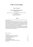
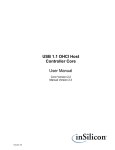
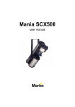
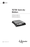
Totalizer Counter S660 Preset Totalizer Counter Easily Programmed from the Front Panel Software Functions Include: Password Display Scaling Set Point Programming Decimal Point Selection Screw Terminal Connectors for Easy Installation Rugged, High-Impact Plastic Case Fits Standard 1/8 DIN Cutout 3.24” (82mm) for Restricted Space Behind Panel Remote Reset Capability Input Variety: Quadrature, Switch, TTL, CMOS, NAMUR, PNP, NPN Optional 5 Amp Relay Outputs The S660 is a versatile totalizing counter that can be adapted to a wide variety of counting, measuring and controlling applications. The control inputs offer several counter operation modes: count/direction, add/add, add/subtract, subtract/subtract, quadrature and reverse quadrature. Optional relay outputs enhance the counter from a passive device to an integral control element for your application. The S660 is compactly designed and features a standard 1/8 DIN case made of PBT-ABS alloy. Screw terminals are standard for easy installation and removal of the meter. The counter is powered from 120 or 240VAC and has a non-volatile EEPROM to retain all programming and count information when the power source is removed or interrupted. The S660 accepts pulses from Quadrature, CMOS or TTL circuits and PNP or NPN devices. The optional 12VDC (100 mA) excitation output module can provide power for external sensors. Other programmable software features include programmable decimal point and a password lockout feature. By using the password feature, the meter’s programming functions and set points are protected from accidental reprogramming. Installation and Panel Cutout 1.77" 45mm 3.56 90.7mm 3.62" 92mm Engineering Label Mounting Requirements The S660 series 1/8 DIN counters require a panel cutout of 1.77" (45mm) high by 3.62" (92mm) wide. To install the counter into a panel cutout, remove the clips from the side of the meter. Slide the meter through your panel cutout, then slide the mounting clips back on the meter. Press evenly to ensure a proper fit. 0.52" 13.2mm 3.93" 99.8mm 3.24" 82.3mm 2.04" 51.8mm 1.76" 44.7mm Engineering Label Placement If replacement of the engineering unit label is required, place the tip of a ball-point pen into the small hole at the base of the engineering label in the bezel. Slide the label up until it pops out. Grasp and remove. Slide the new label half the distance in, then use the ball-point pen to slide it down into place. Specifications DISPLAY Type: 6-digit, 7-segment, red LED Height: 0.56" (14.2mm) Decimal Point: User-programmable Count Direction: “+” indication implied, “-” indication displayed Display Range: -99,999 to +999,999 Output Indicators: 1 and 2 POWER REQUIREMENTS AC Voltages: 120, 240VAC, ±10% Power Consumption: 3VA INPUT RATINGS Current Sinking: 10K⍀ 5% Resistor pull-up to (9.0 - 16 VDC) ⫾10% Current Sourcing: 5.1K⍀ 5% Resistor pulldown to common Minimum Pulse Width: ~5s Low Pass Filter: <200Hz Low Bias: VLT = 1.6V ⫾10% VUT = 3.6V ⫾10% High Bias: VLT = 5.0V ⫾10% VUT = 7.0V ⫾10% Count Rate: 20KHz (Pulse Max) 5KHz (Quadrature X4 Max) Maximum Voltage Input A, B, and User: 30VDC (Max) ENVIRONMENTAL Operating Temp.: 0°C to +40 °C Storage Temp.: -10 °C to +60 °C Relative Humidity: 0-80% for temperatures less than 32°C, decreasing linearly to 50% at 40 °C Ambient Temperature: 25°C Temp. Coefficient (per °C): ±100PPM/ °C Warmup Time: 15 minutes INPUT User Input: (Display Hold) Display is frozen when the User Input is pulled low. Standard Input: VLT ⬉0.2VDC guaranteed low VUT = 3.0VDC (max) Quadrature Input: VLT ⬉ 0.9VDC VUT =3.15VDC (max) MECHANICAL Bezel: 3.93" x 2.04" x .52" (99.8mm x 51.8mm x 13.2mm) Depth: 3.24" (82mm) Panel Cutout: 3.62" x 1.77" (92mm x 45mm) Case Material: PBT-ABS Weight: 9oz (255.1g) Wiring Diagram ! VAC VAC RESET COMMON POWER Denotes module position 4 at rear of counter Power Supply 120 VAC or 240 VAC power connection Remote Reset Active low 0.2V performs primary reset AC Power Module Power Module: The AC power module allows the S660 to be operated from standard 50/60 Hz line power. The power module will be configured as 120 or 240VAC per markings on the back panel. Ensure the input rating of the supply matches your line voltage. The power supply module has provisions for a hard-wire Count Reset. This control can be a switch, relay contact or solid state device. The reset circuit is independent of the power circuit. Input Module: The DIP switch SW1 is used to set up the counter to conform to the electrical characteristics of the sensor or signal being detected. Switch positions 1-3 configure channel B, while switches 46 configure channel A. These switches select bias (threshold voltages), low pass filter (enable/disable) and sensor type (sink or source). Refer to the sensor’s documentation for related information. Denotes module position 1 at rear of counter A INPUT COMMON USER INPUT Primary Input Connect the input signal to A input and common Inhibit Active low stops counting B INPUT COMMON INPUT Note: The input boards are designed so that selecting sourcing or sinking is based on the type of sensor that is being used. If a PNP (sinking) sensor is being used, set the input board for sinking also (switches 3 and 6 = OFF). If channel B is not used, default settings for switch positions 1 through 3 should be selected. Secondary Input Direction Control or count pulse input The Input module also provides for a User input signal. On the S660, this input serves Standard Input Module as a count enable / disable control. Connecting User to Common will disable counting. Programming Menu Category Parameter Name Choices/Format Description Pass 000 * Password Entry and Verification Access —> denied Password Fail Appears if incorrect password entered. ChPass 000 Password Change Appears if correct password entered. 000 = pass word protection disabled. 001-099 = secures all parameters. 100999 = enable SPs/ ResPos access in display mode. A Chan UP * Down Quad r quad Chan A Mode Select count mode of A channel. B Chan Dir * UP Chan B Mode Select count mode of B channel. Note: If A channel set to Quad or R quad, this item is not accessible. Input Setup Down prescl 1.0 * 0.1 0.01 0.001 scale 01.0000 * CountSetup *Default Setting <— Pre-scale Set prescaling multiplier. Scale Set Display Value scaling multiplier. Values: -9.9999 to 99.9999. Programming (Cont’d) Menu Category Parameter Name Choices/Format Description dp 000000 * 000000. 00000.0 0000.00 000.000 00.0000 0.00000 DP Display Value 1 (Count) Decimal Point location. Affects appearance of RstPos and any associated set point parameters. mmode1 Disabl timmed Latch * bound Output 1 Mode Set the mode of operation for Output 1. Can be disabled, timed, latched or boundary mode. Timmed <— Latched <— SP1=Lo <— —> At SP1 —> At SP1 * —> SP2=hi Output 1 Bindings Reminder message indicates which and how the set points are used for comparison. Which message is displayed is determined by the Output 1 Mode selected. Delay1 010.00 * Delay 1 Output 1 delay time. Appears only if Output 1 mode set to timed. Until1 Reset * SP1 SP2 SP3 SP4 RstPos Until 1 Output 1 latched until parameter. Appears only if MMode2 Disabl timmed Latch * bound Output 2 Mode Set the mode of operation for Output 2. Can be disabled, timed, latched or boundary mode. Timmed <— Latched <— SP3=Lo <— —> At SP3 —> At SP3 * —> SP4=Hi Output 2 Reminder message indicates which and how the set points are used for comparison. Which message is displayed is determined by the Output 2 mode selected. Delay2 010.00 * Delay 2 Output 2 delay time. Appears only if Output 2 mode set to timed. Until2 Reset * SP1 SP2 SP3 SP4 RstPos Until 2 Output 2 latched until parameter. Appears only if MMode2 = latch. SP1 000010 * SP1 Set Point #1 Low. Values: -99999 to 999999. Decimal point will appear according to the current DP setting. SP2 000020 * SP2 Set Point #1 High. Values: -99999 to 999999. Decimal point will appear according to the current DP setting. SP3 000030 * SP3 Set Point #2 Low. Values: -99999 to 999999. Decimal point will appear according to the current DP setting. SP4 000040 * SP4 Set Point #2 High. Values: -99999 to 999999. Decimal point will appear according to the current DP setting. RSTPOS 000000 * Reset Position Count value is set to this when an Auto or Manual Reset event occurs. Values: -99999 to 999999. Decimal point will appear according to the current DP position. Areset Disabl * At SP1 At SP2 At SP3 at SP4 AftOP1 AftOP2 Auto Reset Mode Selects when an auto reset function is to occur Disabled at a set point or after output times out. See also the count SETUP OPUT 1 SETUP OPUT 2 SETUP SetPnt SETUP Reset SETUP *Default Setting Mmode1 = latch. RSTPOS parameter in the Setpnt Setup category. Programming (Cont’d) Menu Category Parameter Name Choices/Format Description RstBtn enable * disabl No * Yes Reset Button Enable or disable front panel reset button. Reset SETUP PonRst End Power On Reset select whether count reset event will occur at power-up. Exit Programming Menu *Default Setting Excitation Output Denotes module position 2 at rear of counter The Excitation Module can supply 12VDC at up to 100mA for external sensors or encoders. This excitation is isolated from the counter internal logic supply. When using sensors or encoders that do not have a signal return or imply a signal return that is in common with the supply voltage, a common attachment that ties the excitation supply to the logic input common may be required. ISO+12V ISOCOM + __ _ 12 VDC, 100 mA max --- EXCITATION Single and Dual Relay Modules ! 1 The Single and Dual Relay modules can activate circuit loads of up to 5 amps at 250VAC. A Form C configuration allows use of normally-open (NO) and normally-closed (NC) circuit action. ! Denotes module position 5 at rear of counter N.O. N.C. N.O. 1 COM 250V N.C. COM 5A 250V 5A COM Only the output 1 channel is implemented in the single relay module. 2 N.C. N.O. SINGLE RELAY Single Relay Module RELAYS Dual Relay Module Application Example A Simpson Encoder and Counter are to be used to measure and cut raw material to length. A dual- speed motor is used to allow selection of high speed, low speed and stop. A pneumatic shear allows the material to be cut. Process: Minimum and maximum piece length will be 12 inches and 6000 inches (500 feet) respectively. Material is a light colored textile, so skidding by measuring device is to be avoided. Material is initially to be fed at high speed. In the final six inches, low speed will be used. When the desired length is reached, the motor will be temporarily stopped and the shear activated for two seconds. The feed and cut cycle then resumes for a new piece. Display: Desired display and entry of lengths is in inches with two decimal places (1/100 inch resolution). i.e. The customer would like to enter 0.25 inch increments. Machine Specifications Product Ordering Information Motor and Control: Motor runs in low speed when 120VAC applied to Run-Lo terminal. Hi Speed selected with 120VAC to Run-Hi Terminal. Maximum control current is 3 amps at either terminal. Hi speed = 1725 RPM, Lo speed = 430 RPM. In the application example, a Simpson S660 Preset Totalizing Counter with a 120VAC power supply, Quadrature Input, Dual Relay Output, and 12VDC excitation is used (catalog no. S660-1-2-2-1-0). The encoder used is the SE Quadrature Encoder with 600 pulses-per-revolution (SE600). An encoder chariot (46012) and 12” measuring wheel with 83A durameter non-marking tires (46005) are also required. Shear Specifications: The pneumatic cutting blade is activated by applying 120VAC (0.5 amp maximum) to a control valve. Mechanical: A motor reducer and drive pulley result in 1” of linear travel for every five motor revolutions. Application Example (Cont’d) CHANNEL A-WHITE CHANNEL B-GREEN A INPUT COMMON QUADRATURE ENCODER + USER INPUT B INPUT COMMON COMMON (BLACK) INPUT ISO+12V + __ _ + --ISOCOM EXCITATION QUADRATURE EXCITATION CARD INPUT CARD POSITIVE-RED Safety Symbols Ordering Information Output Power Supply 120VAC 240VAC The WARNING sign denotes a hazard. It calls attention to a procedure, practice, or the like, which, if not correctly performed or adhered to, could result in personal injury. None One Relay Two Relays 1 2 0 1 2 Other None Basic unit 0 The CAUTION sign denotes a hazard. It calls attention to an operating procedure, practice, or the like, which, if not correctly adhered to could result in damage to, or destruction of part or all of the instrument. Excitation S660 None 12VDC Input Standard Quadrature 0 1 1 2 Accessories Chariot The Chariot is used to mount most cube-style quadrature encoders and measuring wheels. Made of anodized aluminum, the chariot includes mounting hardware and selectable pivotal points. Wheels, tires, and flexible shaft couplings are sold separately. SE Quadrature Encoder 12” Circumference Measuring Wheels with Tires The cube-style, dual-shaft SE Encoder is available with a choice of five different resolutions (pulses/revolution) to handle a broad range of measuring jobs. When the encoder is affixed to a chariot with measuring wheels and wired to one of the S660 series counters, cut-to-length measurement applications are assured an accurate and reliable reading. These 12-inch wheels are precision-machined anodized aluminum with a printed alignment scale. Replaceable tires are available in four different durometers, for use on a wide range of materials including nonmarking tires to prevent tearing, damaging or marking up delicate materials. Pulses Per Revolution Catalog Number 60 100 120 360 600 SE-060 SE-100 SE-120 SE-360 SE-600 Tire Durometer Catalog No. 80A, black tire; longer service life for plastics, metals 83A, non-marking tire for textiles, medium textures 92A, non-marking tire for plastics, metals, coarse wood 70A, non-marking tire for soft textiles 46004 46005 46006 46007 Revised 5/11/04