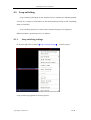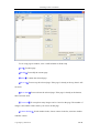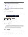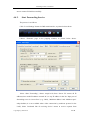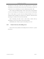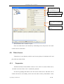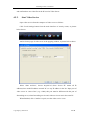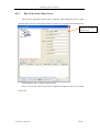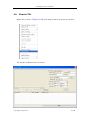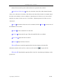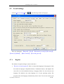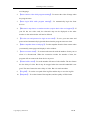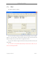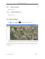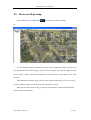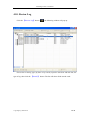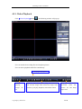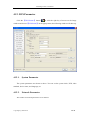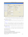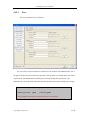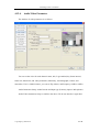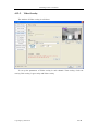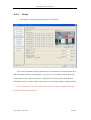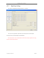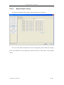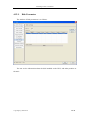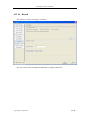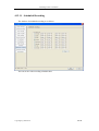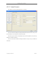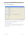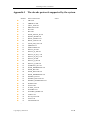
1
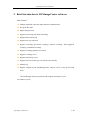
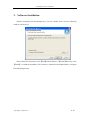
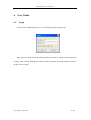
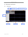
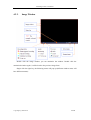
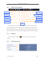
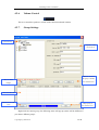
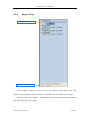
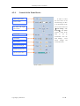
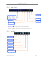
DVS ImageCenter
Manual
(V1.3.1.2)
April 29,2009
DVSImageCenter User Manual
Welcome
Thank you for choosing our DVS Image Center software. Please read the manual
carefully before using. If you have problems which is not answered in the manual please
contact your vendor or the technical support department of our company.
We reserve the right to update the manual without notice.
Copy Right @ TOSI Tech
2 / 56
DVSImageCenter User Manual
Table of Content
Table of Content................................................................................................................................3
1.
General ..............................................................................................................................5
1.1.
Manual Version .........................................................................................................5
1.2.
System Requirement .................................................................................................5
1.3.
Notes .........................................................................................................................6
2.
Brief Introduction to DVSImageCenter software .............................................................7
3.
Software Installation .........................................................................................................8
4.
User Guide ........................................................................................................................9
4.1.
Login .........................................................................................................................9
4.2.
Main Interface and Functions..................................................................................10
4.2.1.
Main Interface .........................................................................................10
4.2.2.
Image Window ........................................................................................ 11
4.2.3.
Channel Control Buttons.........................................................................13
4.2.4.
Talk-Back ................................................................................................13
4.2.5.
Information System .................................................................................13
4.2.6.
Volume Control .......................................................................................14
4.2.7.
Group Settings.........................................................................................14
4.2.8.
Image Group............................................................................................16
4.2.9.
Control of the Front Device.....................................................................17
4.2.10.
Image Control..........................................................................................18
4.2.11.
Functions .................................................................................................18
4.3.
Loop switching........................................................................................................19
4.3.2.
Switching Pagination...............................................................................21
4.4.
Forwarding Server...................................................................................................21
4.4.1.
Preparation ..............................................................................................21
4.4.2.
Start Forwarding Service.........................................................................22
4.4.3.
Connect device by forwarding server......................................................23
4.5.
Video Server............................................................................................................24
4.5.1.
Preparation ..............................................................................................24
4.5.2.
Start Video Service..................................................................................25
4.5.3.
Play Video from Video Server.................................................................26
4.6.
Remote File .............................................................................................................27
4.7.
Local Settings..........................................................................................................29
4.7.1.
Regular ....................................................................................................29
4.7.2.
User .........................................................................................................29
4.7.3.
Scheduled Recording...............................................................................29
4.7.4.
Recording ................................................................................................29
4.7.5.
Alarm.......................................................................................................29
4.7.6.
EMail.......................................................................................................29
4.7.7.
Data Forwarding......................................................................................29
4.7.8.
Video Recording Server ..........................................................................29
Copy Right @ TOSI Tech
3 / 56
DVSImageCenter User Manual
4.8.
Electronic Map ........................................................................................................29
4.9.
Electronic Map Setup ..............................................................................................29
4.10.
Review Log .............................................................................................................29
4.12.
DVS Parameter........................................................................................................29
4.12.1.
System Parameter....................................................................................29
4.12.2.
Network Parameter..................................................................................29
4.12.4.
Audio/Video Parameter ...........................................................................29
4.12.5.
Video Overlay .........................................................................................29
4.12.6.
Motion .....................................................................................................29
4.12.7.
Digital Input Settings ..............................................................................29
4.12.8.
Digital Output Settings............................................................................29
4.12.9.
Disk Parameter ........................................................................................29
4.12.10.
Record .....................................................................................................29
4.12.11.
Scheduled Recording...............................................................................29
4.12.12.
Terminal Parameter .................................................................................29
4.12.13.
DVS System Maintenance ......................................................................29
Appendix I The decode protocols supported by the system.........................................................29
Appendix II Troubleshooting .......................................................................................................29
Copy Right @ TOSI Tech
4 / 56
DVSImageCenter User Manual
1. General
1.1.
Manual Version
Manual Version
V1.3.1.2
V1.3.0.18
V1.3.0.17
V1.3.0.16
1.2.
Differences with previous versions
Time of updated
Revised bugs in “add/delete device” of 2009-4-29
change digital map; added length limit
of the settings, etc.
Revised bugs in pre-recording; added
Korean language, etc.
Added
transferring
server
and
recording server, added searching from
recording server for remote file.
Added Email alarm, remote recording
playback, and set buffer locally, etc.
System Requirement
Operating System
◆
Windows 2000 and Windows XP (English or Simplified Chinese Edition)
Minimum Requirement
◆ CPU: Pentium 1.1Ghz
◆ Memory: 128MB
◆ Video Card: TNT2
◆ Sound Card: Necessary when audio monitoring and two-way talk-back is in use
◆ Hard Drive: Minimum 40G if recording is in use
Recommended System
◆ CPU: Pentium 2.6Ghz
◆ Memory: 512MB
◆ Video Card: NVidia Geforce FX5200 or ATI RADEON 7000(9000) series,
128M memory (to support hardware zoom function)
Copy Right @ TOSI Tech
5 / 56
DVSImageCenter User Manual
Software Requirement
◆ Inter Explorer 6.0 or above
◆ DirectX 8.0or above
1.3.
Notes
◆ The IP CAM in this manual refers to IP Camera. DVS refers to Digital Video Server.
The operation of DVS also applies to IP CAM, except there are different
descriptions otherwise.
◆ Single click refers to click the left key of mouse one time
◆ Double click refers to click the left key of mouse two times
Copy Right @ TOSI Tech
6 / 56
DVSImageCenter User Manual
2. Brief Introduction to DVSImageCenter software
Main Features:
◆ Manage unlimited video and audio channels simultaneously
◆ Set up the IP CAM
◆ Digital map function
◆ Support previewing and rotate monitoring
◆ Support audio monitoring
◆ Support two-way talk back
◆ Support recording (pre-alarm recording, manual recording, alarm-triggered
recording, scheduled recording)
◆ Support recording playback and search
◆ Support recording server
◆ Support transferring server
◆ Support Pan/Tile control, pre-set, transfer, track transfer
◆ Manage log
◆ Support snapshot by the DVSImageCenter software on PC or by the IP CAM
itself
The DVSImageCenter has powerful and complete functions for your
surveillance system.
Copy Right @ TOSI Tech
7 / 56
DVSImageCenter User Manual
3. Software Installation
Find the installation file DVSImageCenter_Vxx.exe, double click it and the following
windows will show up:
Please follow the instruction, click 【Next】until the button of 【Finish】shows up. Click
【Finish】 to finish the installation. The software is installed to the default folder C:\Program
Files\DVSImageCenter.
Copy Right @ TOSI Tech
8 / 56
DVSImageCenter User Manual
4. User Guide
4.1.
Login
Click the file “DVSImageCenter.exe”, the following window will pop up:
图 1
Input your user name and password (the default user name is “admin” and the password
is empty. After clicking 【OK】, the software starts to initialize. The main interface will show
up after a few seconds:
Copy Right @ TOSI Tech
9 / 56
DVSImageCenter User Manual
4.2. Main Interface and Functions
4.2.1.
Main Interface
System time
Image window and status
About, minimize, or close the window
Grouped
devices area
图 2
Display control
Copy Right @ TOSI Tech
Channel control
Functions
10 / 56
DVSImageCenter User Manual
4.2.2.
Image Window
Double click the image window, you can maximize the window. Double click the
maximized window again, it will be back to the previous image form.
Single click the right key, the following menu will pop up (different window status will
have different menus):
Copy Right @ TOSI Tech
11 / 56
DVSImageCenter User Manual
Cycle switch assign: to set the video channel of each display window.
Full Screen: full screen display without grouped windows and function buttons.
Screen View: to set how many windows per screen with same function as the
button on the lower left corner.
Screen View: to add, delete and modify DVS and its display group.
Delete preview window: To delete the link between the current window and the
channel of DVS
Image control: to connect, disconnect the image channel of this window; to
start or stop recording; and to capture snapshot.
Login & logout: to login and logout DVS.
Notes: when you login or logout, all relevant windows of DVS will login or
logout at the same time. After you login, you can control pan/tile and set up the
DVS.
DVS Settings: to set up the DVS of the image window.
Remote file: to search, playback and download the recording and snapshot.
Check Alarm & Uncheck Alarm
Page control: to control all the windows on the current page.
Copy Right @ TOSI Tech
12 / 56
DVSImageCenter User Manual
4.2.3.
Channel Control Buttons
Lgoin
Volume control
Logout
Audio monitoring on/off
DVS settings
Delete alarm
Connect image
Talk-back on/off
Start/stop recording
Disconnect image
Snapshot
The operations of Connect & Disconnect Image, Volume control, Audio monitoring
on/off, and Snapshot are for the current image window. The operations of Login, Logout,
DVS settings, Talk-back on/off, and Delete alarm are for the DVS of the image window. The
Delete alarm operation is to delete all the alarms triggered by the DVS of the image window.
4.2.4.
Talk-Back
Click the Talk-back on/off button
, you can talk to the current DVS from your
viewer PC.
4.2.5.
Information System
Copy Right @ TOSI Tech
13 / 56
DVSImageCenter User Manual
4.2.6.
Volume Control
This is to control the speaker’s volume of the current monitored window.
4.2.7.
Group Settings
Current Group
Properties of the
current server
Add new servers to
the group or modify
Save or cancel
the selected server
changes
Servers in the LAN
Search servers in the
Add property of
LAN
the selected server
Right click the current group, the following menu will pop up (menu will be different if
you choose different group):
Copy Right @ TOSI Tech
14 / 56
DVSImageCenter User Manual
Add a new group
Delete the current group
Modify the current group
Delete the selected server
Set up the selected camera
Copy Right @ TOSI Tech
15 / 56
DVSImageCenter User Manual
4.2.8.
Image Group
Group information
Group/Control switch
In the grouped window, the status of severs and cameras will be shown: gray color
means it is disconnected; blue color means it is connected; red color means it is alarming.
Check the “Show server address”. The IP address (or domain name) and port information
will show up after the server name.
Copy Right @ TOSI Tech
16 / 56
DVSImageCenter User Manual
4.2.9.
Control of the Front Device
Alarm output control
In order to control
the front device of the
Preset, transfer
selected image, you have
to set the decoder of the
Up, down, left, right,
device. Please refer to the
auto rotation
【Local Settings - P/T
Protocol】. The default
protocol is built in the
Zoom in/out
Iris add/sub
NVS
(it
can
be
downloaded
from
the
NVS Settings – Front
Device
Focus control
Settings
and
saved in the NVS).
Rain brush and Light
Rotation present point
Pan/Tile speed control
Copy Right @ TOSI Tech
17 / 56
DVSImageCenter User Manual
4.2.10.
Image Control
Next Page
1 window
4 windows
9 windows 16 windows
25 windows 36 windows
Full Screen
Cycle Switch
Last Page
Image Window Style
【Image Style】is to turn on/off the status bar of the window
Page turn manually or auto cycle are valid after you turn on page cycle.
4.2.11.
Functions
Electronic map
Elecmap setup
Group settings
Local settings
Log search
Local play-back
Copy Right @ TOSI Tech
18 / 56
DVSImageCenter User Manual
4.3. Loop switching
Loop switching is designed for this situation: Device channels of CMS management
exceeds 36 (or images of all channels are not totally displayed owing to lack of handling
ability of CMS PC).
Loop switching means user watches all the channels through cycle displaying
different channels, operation process is as follows:
4.3.1.
Loop switching settings
In any area right click to choose【Loop switching settings】,as below picture:
Loop switch assign appreances as below picture:
Copy Right @ TOSI Tech
19 / 56
DVSImageCenter User Manual
To set Loop page in window, click “confirm”button to finsh setup
【Add】To add a page.
【Modify】To modify the current page.
【Delete】To delete the selected page.
【Move up】To move up the selected page. If the page is already at the top, then it will
not work.
【Move down】To move down the selected page. If the page is already at the bottom,
then it will not work.
【View mode】To set up how many images can be viewed on the page. The number of
images is the number of the camera you can set on that page.
【Camera Settings】In left window index, choose camera in the list, associate window
with this camera
Copy Right @ TOSI Tech
20 / 56
DVSImageCenter User Manual
【Delete camera】To delete association the window and camera
【Clear】To clear all cameras associated the current page.
【Move up】【Move down】To adjust camera sequence
【Page stay time (Seconds)】To set the stay time of the selected page during the image
Loop (10-600 seconds).
4.3.2.
Switching Pagination
In the right side of main interface, the first three command buttons are used to switch
pagination, manual switching and auto-cycle page are available, as picture below shows:
Previous
Page
Cycle
Page
Next Page
In the process of switching pagination, current pagination name displays in the main window.
4.4. Forwarding Server
To lower down the load of IP CAM Board and decrease the occupancy factor of
network bandwidth, forwarding server is used as the transferring center in order to allow
many users to access to one same IP CAM. Please refer to the following steps:
4.4.1.
Preparation
Install CMS software in 2 PC, one PC is used as forwarding server, the other is used
as Client, 2 PC is connected by network.
Set IP CAM’grouping and names in one PC used as forwarding server, and make
Copy Right @ TOSI Tech
21 / 56
DVSImageCenter User Manual
sure to connect IP CAM successfully.
4.4.2.
Start Forwarding Service
The process is as follows:
Click “Local Settings” button in CMS main interface, as picture below shows:
Choose “Transmit” page in the popping window, as picture below shows:
Select “Start Forwarding”, choose Any(0.0.0.0) from “Server IP” means all IP
address(aim to multi-IP address network PC) or any IP address in the list. Input port of
forwarding server in “Server Port” (e.g.: 5000), “Multicast address” and “Multicast port”
adopt default (it is not available when video connection by multicast protocol in the
LAN); Select “backward link of receiving device” means to receive requests from
Copy Right @ TOSI Tech
22 / 56
DVSImageCenter User Manual
forwarding server when login of DVS device (no supply function of connection of
forwarding server by current IP CAM); “Max user limit” means quantity of Clients who
are allowed to access to forwarding server on-line simultaneously (default is OK).
Select “Setup of forwarding parameter” means to allow Client to setup parameters
of device by forwarding server; forwarding server connects this device automatically
when a Client requests to log into this device through forwarding server, and no
connection between forwarding server and this device. Otherwise, connection between
forwarding server and this device must be done beforehand.
Select “Forwarding video data” means to allow Client to monitor video by
forwarding server, click “Copy” button to copy onto other channels.
When finished, click “Confirm” to quit, now forwarding service is run.
4.4.3.
Connect device by forwarding server
Need to fill in correct parameters when adding devices into Client PC, as picture
below shows:
Copy Right @ TOSI Tech
23 / 56
DVSImageCenter User Manual
the same as the name
of forwarding server
IP Adds of forwarding server
Port of forwarding server
User name of forwarding
server
Password of forwarding
server
When finished, click “Confirm” to quit.
Now can connect device in Client PC by forwarding server, the process is the same
as direct devices’connection.
4.5. Video Server
Video Server is one function, which is used to store plenty of video data in PC and
play video by remote Client.
4.5.1.
Preparation
Install the software of Surveillance center in 2 PC, one PC is used as Video Server,
the other is used as Client, 2 PC is connected by network.
Set devices’grouping and names in one PC used as Video Server, and make sure to
connect the devices successfully, and to run local video record by Surveillance center,
Copy Right @ TOSI Tech
24 / 56
DVSImageCenter User Manual
and confirm there are video files in the PC used as Video Server.
4.5.2.
Start Video Service
Open video service from the computer of video server as follows:
Click Local Settings button from the main interface of security center, as picture
below shows:
And to choose page of video server in the popping window, as picture below shows:
Select “Start Archiver”, choose Any(0.0.0.0) from “Server IP” means all IP
address(aim to multi-IP address network PC) or any IP address in the list. Input port of
video server in “Server Port” (e.g.: 6000), this port must be different with the port of
forwarding server, when forwarding service and video service are run in the same PC.
When finished, click “Confirm” to quit, now the video service is run.
Copy Right @ TOSI Tech
25 / 56
DVSImageCenter User Manual
4.5.3.
Play Video from Video Server
Set the device parameters in the client’s computer, when adding the devices, make
sure that name of server is the same as name of video server. As the picture below shows:
The same as name of
video server
When finished, click “Confirm” button to quit.
Now it is ok to play video in the client’s computer through the video server, please
refer to 4.6.
Copy Right @ TOSI Tech
26 / 56
DVSImageCenter User Manual
4.6. Remote File
Right Click to choose 【Remote File】in the Image window, the picture is as follows:
The interface of Remote File is as follows:
Copy Right @ TOSI Tech
27 / 56
DVSImageCenter User Manual
Remote File Search, Play-back and Download are operated in the window.
【Search from Video Server】Select it to check the video files of the channel from the
video server, otherwise to check the video files saved in the disk of the device terminal. Input
the video server address in “Server Address”; input the port of video server in “Server Port”;
input the user name of video server in “User Name”; input the password of video server in
“Password”.
【Server】Input name of the device to be searched, left click【Choose】to choose one of
the added devices to search.
【Channel】Choose channel No.of video file.
【File Type】Choose the file type: Video file and JPEG file are available.
【Start Time】Input start time of Search.
【End time】Input end time of search.
【Search】Start to search the appointed file, list below displays all related file
information; double click one file, or choose one file and click
to play this file.
【Download】Download the appointed file to local PC; download speed displays on the
progress bar.
Copy Right @ TOSI Tech
28 / 56
DVSImageCenter User Manual
4.7. Local Settings
Click the【Local Settings】button
,the following window will pop up:
There are eight pages: 【Regular】,【User】,【Scheduled recording】,【Recording】,
【Alarm】,【EMail】, 【Data Transfer】, 【Recording Server】.
4.7.1.
Regular
The window of regular settings is same as the above.
1. 【Current selected language】: This is to choose the language of the program. It has
three built-in languages: Simplified Chinese, Traditional Chinese, and English. The
source file is in the installation directory \Language folder. You can add your own
language. The default is the same language as it of your operating system. The
program will search language automatically when it starts. You can also choose your
Copy Right @ TOSI Tech
29 / 56
DVSImageCenter User Manual
own language.
2. 【Auto connect video while program running】: To connect the video of image when
the program starts.
3. 【Auto login DVS while program running】: To automatically login the front
devices.
4. 【Electronic map shows on another monitor (require dual video card support)】: If
your PC has two video cards, the electronic map can be displayed on the other
monitor so the main window will not be affected.
5. 【Use the user and password to login at next time】: To save your user name and
password and automatically login with them when the program starts next time.
6. 【Show snapshot when switch page】: To take snapshot from the front camera when
you manually rotate pages and display it in the window.
7. 【Auto reconnect times】: To reconnect the network with the number of time you set
when it is disconnected. When the connection reaches the number of time, the
program will not connect the front device any more.
8. 【Frame buffer count】: To set the number of frames of video buffer. The less frames
the less delay of video. But it may be stopped when the network bandwidth is not
good. The more frames the more delay of video. But it is much smoother.
9. 【Log file】: To set the save path of the log files and the days to save the log file.
10. 【Snapshot】: To set the format of the snapshot, and the quality of JPG format.
Copy Right @ TOSI Tech
30 / 56
DVSImageCenter User Manual
4.7.2.
User
The window of local user is as follows:
This is to add, delete, and modify the users and their authorization.
Notes: Only the administrator can delete or modify other users. Users can only change
their own passwords.
Copy Right @ TOSI Tech
31 / 56
DVSImageCenter User Manual
4.7.3.
Scheduled Recording
The window of scheduled recording is as follows:
This is to set the recording time for each camera. You can set two time periods every day.
The schedules can be copied for selected cameras. Click the 【OK】to save the settings.
Copy Right @ TOSI Tech
32 / 56
DVSImageCenter User Manual
4.7.4.
Recording
The window of record is as follows:
1.
When you save recording on the hard drive, you can choose which disk to save.
Click the 【OK】to save your settings.
2.
【While not enough disk space】 is to delete previously saved files when the hard
drive is full.
Notes: previous files are those saved by 0:00 am on that day.
3.
Saving path: root \DVSFile\date\DVS IP address (port)\ CH_0X\record
4.
【Time Limit】is to set the time of recording.
Copy Right @ TOSI Tech
33 / 56
DVSImageCenter User Manual
4.7.5.
Alarm
The window of alarm is as follows:
【Alarm sound】: To choose the sound of alarm. Click
to choose the sound you like.
【Alarm action】: To set the alarm-triggered actions, including Playing Sound, Popup
Electronic map, Popup Alarm information dialog, Send email, Connect video, and Record, etc.
You can also set the Record duration time and prerecord time.
【Alarm clear】: To automatically clear alarm. When the alarm is not triggered again during
the set time period, the program will delete the alarm automatically.
Copy Right @ TOSI Tech
34 / 56
DVSImageCenter User Manual
4.7.6.
EMail
The window of Email is as follows:
You can set the Email on this page, including various Email address, receivers, senders,
subjects, etc. The mail content is valid only when sending test email. The mail content will
change according to the type of alarm when it is triggered by the alarm.
You can set the condition to trigger the email alarm: motion, probe alarm, video lost, and
connect failed.
Note: The email is sent by SMTP (Simple Message Transfer Protocol). Make sure your
mail server should support SMTP.
Copy Right @ TOSI Tech
35 / 56
DVSImageCenter User Manual
4.7.7.
Data Forwarding
Please refer to 4.4.
4.7.8.
Video Recording Server
Please refer to 4.5.
4.8. Electronic Map
Click【Electronic map】button
,the following window will pop up:
The electronic map shows the location of every camera and detector. When there is alarm,
the electronic map will pop up, and the alarming camera or detector will flash if it is marked
on the map.
Copy Right @ TOSI Tech
36 / 56
DVSImageCenter User Manual
4.9. Electronic Map Setup
Click the【Elecmap setup】button
, the following window will pop
up:
You can mark the cameras and detectors on the map so people can clearly see them. First
you should make an electronic map by yourself. On the map list, you click the right key of the
mouse, choose “Add” to add this map and name it. Double click its name then you can open
the map.
After adding the electronic map, you can create cameras and detectors on it. You can see
its video window when you click the camera on the electronic map.
After you have the electronic map, it will pop up when there is alarm and the alarming
camera or detector will flash.
Copy Right @ TOSI Tech
37 / 56
DVSImageCenter User Manual
4.10. Review Log
Click the 【Review Log】button
, the following window will pop up:
Choose the reviewing type (by date or by search), input the start date and end date, the
type of log, then click the 【Search】 button. The list will show all the search result.
Copy Right @ TOSI Tech
38 / 56
DVSImageCenter User Manual
4.11. Video Playback
Click【Video Playback】button
, the following window will pop up:
User can search the recording files and snapshot pictures.
User can select playback multi files continuously.
Playing time progress
Choose
playing
images
#4
#1-
Copy Right @ TOSI Tech
They are: Open, Play, Pause, Stop, Fast backward,
Fast forward, Single frame backward, Single frame
forward, Cycle play, Snapshot, and Volume control.
They are: Full screen,
show/hide status bar,
Choose all, and Keep
aspect ratio
39 / 56
DVSImageCenter User Manual
4.12. DVS Parameter
Click the 【DVS Param】 button
, or click the right key of mouse on the image
window and choose 【DVS Param】 on the popup menu, the following window will show up:
4.12.1.
System Parameter
The system parameters are shown as above. You can set the system clock, NTP, video
standard, device name, and language, etc.
4.12.2.
Network Parameter
The window of network parameters are as follows:
Copy Right @ TOSI Tech
40 / 56
DVSImageCenter User Manual
You can set the IP address of DVS, Subnet mask, Gateway, MAC address, data port, Web
port, and DHCP, etc. If the DVS is in a LAN, make sure its IP address does not conflict with
the IP of other devices in the LAN.
【Web port】: To change of the web port of IE browser provided by Web Server of the
DVS.
【DDNS】:
When the DDNS function is enabled, DVS will report to DDNS its IP
address (LAN) of the dynamic IP address received from router. You should input the IP
address or the domain name of the DDNS. When the DDNS is a domain name, make sure the
DNS IP address is correct.
【Enable Center mode】:
You should set the correct center IP address and service port,
if you want the front camera to take snapshot or RS232 to collect data and the DVS is
connected with the centrer.
Video Server Network Guide:
The video server uses the following default ports:
TCP: 80 (Web port), 5000 (data port, TCP data port, talk-back data port)
Multicast port: Multicast start port + channel number (0~3)
Copy Right @ TOSI Tech
41 / 56
DVSImageCenter User Manual
4.12.3.
User
The User parameters are as follows:
You can create 12 user accounts for each DVS. One of them is the administrator, one is
the guest, and the rest ten accounts are operators. The operators can change their user names
or passwords. The administrator and the guest can only change their passwords. The
administrator can set the DVS while the operators and the guest cannot change any settings.
Default administrator: admin
password: admin
Default guest name:
password:: guest
guest
Note: both the user name and password are case sensitive.
Copy Right @ TOSI Tech
42 / 56
DVSImageCenter User Manual
4.12.4.
Audio/Video Parameter
The window of video parameters is as follows:
You can set the video for each channel: name, title, Logo enabled, key frame interval,
frame rate, Mask area, and video parameters (luminosity, chromatograph, contrast, and
saturation). If it is a CMOS camera, you can set Flip, Mirror, and Frequency (50Hz or 60Hz).
Audio Parameters Setup: Audio Decode and Input type (Linearity input or Microphone).
Audio/Video Parameters Setup is similar to the above. We do not describe it again here.
Copy Right @ TOSI Tech
43 / 56
DVSImageCenter User Manual
4.12.5.
Video Overlay
The window of Video overlay is as follows:
To set up the parameters of Video overlay in each channel: Time overlay, Code rate
overlay, Title overlay, Logo overlay and Video overlay.
Copy Right @ TOSI Tech
44 / 56
DVSImageCenter User Manual
4.12.6.
Motion
The window of motion detection parameters is as follows:
You can set the motion detection parameters of each channel here: motion detection area
(The monitoring window is separated into 11 x 9 pieces. You can single click the piece you
want to detect to set or remove detection), working hours, sensitivity, auto alarm deletion
(alarm delay time), associated output, associated record, associated snapshot, and Send Email.
note: this function is not recommended as the JPG file created by snapshot will occupy
resources of DVS and the network.
Copy Right @ TOSI Tech
45 / 56
DVSImageCenter User Manual
4.12.7.
Digital Input Settings
The window of Digital Input settings parameters is as follows:
You can set every probe here: probe name, detect time period, associated output,
associated record, associated snapshot, and Send Email.
Note: this function is not recommended as the JPG file created by snapshot will occupy
resources of DVS and the network.
Copy Right @ TOSI Tech
46 / 56
DVSImageCenter User Manual
4.12.8.
Digital Output Settings
The window of Digital Output Settings (alarm annunciator) is as follows:
You can set the name of annunciator and its working time period. Within the working
hours, the annunciator can be triggered by motion detection or other probes, if they output
alarms.
Copy Right @ TOSI Tech
47 / 56
DVSImageCenter User Manual
4.12.9.
Disk Parameter
The window of Disk parameters is as follows:
You can see the information about the disk installed on the DVS, and make partition or
format it.
Copy Right @ TOSI Tech
48 / 56
DVSImageCenter User Manual
4.12.10. Record
The window of video recording is as follows:
You can set the video recording and manually recording control here.
Copy Right @ TOSI Tech
49 / 56
DVSImageCenter User Manual
4.12.11. Scheduled Recording
The window of scheduled recording is as follows:
You can set the video recording schedules here.
Copy Right @ TOSI Tech
50 / 56
DVSImageCenter User Manual
4.12.12. Terminal Parameter
The window to set DVS terminal parameters is as follows:
You can set the DVS COM ports and download Pan/Tile protocols to DVS. Also you can
set the IP address of each channel for the Pan/Tile decoder.
The built-in protocol which is downloaded from the Pan/Tile should have correct bit rate,
and data bit of RS485 COM ports.
The bit rate and data bit of RS232 COM ports should be correctly set if you use RS232 to
collect data.
Copy Right @ TOSI Tech
51 / 56
DVSImageCenter User Manual
4.12.13. DVS System Maintenance
The windows of DVS System Maintenance is as follows:
DVS Update: Click【…】button,choose the right update file, and click【Update】button
to start updati. DVS restarts after update is finished with notice.
【Restart】button: Restart DVS
【Factory default】button:All DVS parameters including Network Parameters are
restored to Factory default. The physical IP address will not change. Please be cautious
before click this button!
Copy Right @ TOSI Tech
52 / 56
DVSImageCenter User Manual
Appendix I The decode protocols supported by the system
◆
◆
◆
◆
◆
◆
◆
◆
◆
◆
◆
◆
◆
◆
◆
◆
◆
◆
◆
◆
◆
◆
◆
◆
◆
◆
◆
◆
◆
◆
◆
◆
◆
◆
◆
◆
◆
Number
1
2
3
4
5
6
7
8
9
10
11
12
13
14
15
16
17
18
19
20
21
22
23
24
25
26
27
28
29
30
31
32
33
34
35
36
37
…
Copy Right @ TOSI Tech
Name of Protocols
AB.COD
ABK2001.COD
AILIC_SAE.cod
DRAGON.COD
EE.COD
HY.COD
JIAJIE_PELCO_D.cod
Kallaite_DOME.cod
KONY_M800CI.cod
KONY_TMCIA.cod
LILIN_PIH_1016.cod
MTR600.cod
NEWCODER.cod
PELCO_D.COD
PELCO_D_AB.cod
PELCO_D_NS_1.cod
PELCO_D_NS_2.cod
PELCO_P.COD
PELCO_P_NS.cod
PELCO_P_WD.cod
SAMSUNG_641.cod
SE300_SHARPEYES.cod
SE600_HY.COD
SE600_PELCOD.cod
SE600_SHARPEYES.cod
SE600S1_HY.cod
SE600S1_PELCOD.cod
SE600S1_SHARPEYES.cod
SONET.COD
SYYT.COD
TCSTD_Y10.cod
TOTAB01.cod
TOTAB01_DOME.cod
Visdom.cod
W110_PTZ.COD
YAAN.cod
YOULIDVR.cod
Notes
53 / 56
DVSImageCenter User Manual
Appendix II
Troubleshooting
You CANNOT access the IP Camera through DVS Image Center
Possible reason #1: network is not connected properly.
Solution: Use PCs to connect the network to test the network. First check the cable
connection, and PC virus problem, then ping the IP address of each PC until there is no
problem anymore.
Possible reason #2: The IP address of the DVS is occupied by other devices.
Solution: Disconnect the DVS and the network. Connect it with a PC. Then reset its IP
address properly.
Possible reason #3: The IP address of the DVS and the IP Camera may be in different
subnet.
Solution: Check their IP address, subnet mask, and gateway to see if they are in same
subnet.
Possible reason #4: The web port is changed.
Solution: Contact your LAN network administrator to get the right information of web
port.
Possible reason #5: Unknown
Solution: Press the reset button on the back of the DVS to make the DVS to default
settings. Then restart it. The default IP address is 192.168.0.250. The subnet mask is
255.255.255.0. And the DHCP is enabled.
You CANNOT control the Pan/Tile and camera
Possible reason #1: Cable is not connected properly.
Solution: Reconnect the Pan/Tile or the camera together with the DVS.
Possible reason #2: The decoder protocol, the IP address, or the bit rate is not set
properly.
Solution: Double check the settings and make sure they are correct.
You CANNOT hear sound when monitoring
Copy Right @ TOSI Tech
54 / 56
DVSImageCenter User Manual
Possible reason #1: There is not audio input.
Solution: Check the audio cable connection of the DVS.
Possible reason #2: The audio settings of the IP Camera are not opened
Solution: Check the audio settings of the IP Camera.
The audio quality is poor
Possible reason #1: If there is a lot of noise and the sound is distorted, please check
whether the audio input is line in. In many cases, when the audio input is not line
in (for example, an amplified microphone is used instead), the audio signal will
not comply with the input electric level. It leads to saturated distortion.
Solution: Set the proper line in audio input allowed by the DVS.
Why the data cannot get through the network switch?
Possible reason #1: The IP address is wrong if it is a two-layer switch.
Possible reason #2: The port and the MAC address are not bound together.
Possible reason #3: The switch’s firewall is not set properly.
Solution: When you check about the possible reasons, make sure you connect a
PC to the network and type “ping” in the CMD mode. Check the result
information. If the PC cannot “ping” the DVS correctly, there must be some
problem in the settings. If the IP address is bound with the MAC address, similarly,
you should add a new binding of the IP address and MAC address of the DVS in
the switch. If the DVS is not included in the switch’s firewall, then you should
reset the switch’s firewall with the correct web ort and the data port of the DVS.
Default settings of the DVS
IP address:
192.168.0.250
Subnet mask: 255.255.255. 0
Gateway: 192.168.0.1
Data port: 4000
Copy Right @ TOSI Tech
Web port: 80
Multicast: random
Multicast start port: random
DHCP: enabled
55 / 56
DVSImageCenter User Manual
Thank you for choosing our product
Copy Right @ TOSI Tech
56 / 56