1
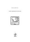
OWNER’S MANUAL
SPLIT AIRCONDITIONING SYSTEM
TAS-09SVH / 12SVH
Safety instructions
PLEASE READ THE FOLLOWING SAFETY
INSTRUCTIONS BEFORE IN-STALLING AND
OPERATING THE UNIT:
This air conditioner meets strict safety and operating
standards. The installer of this unit must install or
service this unit so it operates safe-ly and efficiently.
IMPORTANT NOTES
•Adhere to all safety instructions and warnings
throughout this manual.
•Read this manual carefully before installing or operating
this unit to become familiar with its features and obtain
the perfor-mance that will bring you continued
enjoyment for many years.
•Follow each installation or repair step exactly as shown
in the manual.
•Observe all local, state and national electric codes.
Contact your local government for more information on
electrical codes.
The lightning flash with arrowhead
symbol, within an equilateral triangle is
intended to alert the user to the
presence of uninsulated dangerous
voltage within the product’s enclosure
that may be of suffi-cient magnitude to
constitute a risk of electric shock to
persons.
The exclamation point within an
equilateral triangle is intended to alert
the user to the presence of im-portant
operating and maintenance (servicing)
in-structions in the literature
accompanying the appli-ance.
Contact Installer if Necessary:
The installation instructions are for a experienced
installer. If you are not an experienced installer,
contact a local installer for help.
If Unit is Installed Improperly:
The manufacturer shall in no way be responsible for
improper instal-lation or maintenance service,
including failure to follow the instruc-tions in this
manual.
Precautions When Wiring:
•Do not plug in the unit until all connections (tubing,
drain hose,mounting, etc.) have been made and
double-checked.
2
•High voltages are present in this unit and are very
dangerous. Please refer to these instructions and
diagrams when wiring. Improper connections or
inadequate grounding can cause acciden-tal injury.
•This unit must be grounded in accordance with local
electrical codes.
•Connect wires and pipes securely and tightly as
loose connec-tions/ wiring may cause overheating at
connections and a possible fire hazard.
Precautions When Transporting:
•When transporting the unit, be very careful and get
help as the units are very heavy. Be careful of sharp
edges on the units also.
Precautions When Installing:
•When installing in a ceiling or wall, make sure the
ceiling/wall is strong enough to hold the unit’s
weight. A frame may be necessary for added
support.
•When installing in a room, make sure the tubes are
well insulat-ed to protect the walls and furniture from
sweating of the tubes.
•When installing in moist or uneven locations, make
sure to use a raised level concrete pad or concrete
blocks to provide a level, solid foundation for the
outdoor unit; this prevents water damage and
vibration.
•When installing in an area of high winds, make sure
to securely anchor the outdoor unit down with bolts
and a metal frame.
When Connecting Refrigerant Tubing:
•Keep all tubing as short as possible.
•Use the flare method for connecting tubing.
•Apply refrigerant lubricant to the matching surfaces
of the flare and union tubes before connecting them,
then tighten , making sure not to overtighten.
•Check the tubes carefully for leaks before starting
the test run.
WARNING:
• ELECTRICAL SHOCK CAN CAUSE SEVERE
PERSONAL IN-JURY OR DEATH. ONLY A
QUALIFIED, EXPERIENCED ELEC-TRICIAN/
INSTALLER SHOULD ATTEMPT TO WIRE THIS
SYS-TEM.
• THE APPLIANCE IS NOT INTENDED FOR USE
BY CHIL-DRENOR INFIRM PERSONS WITHOUT
SUPERVISION.
• YOUNG CHILDREN SHOULD BE SUPERVISED
TO ENSURE THAT DO NOT PLAY WITH THE
APPLIANCE
Disposal of Used Electrical &
Electronic Equipment
When Servicing:
•Make sure the power is off and the unit is unplugged
before open-ing the unit to troubleshoot or repair
electrical parts and wiring.
•Keep your fingers and clothing away from any moving
parts.
•Clean up the sight after you finish, making sure no
metal scraps and wiring are left in the unit.
•The Air conditioner shall be installed in accordance
with the na-tioned wiring regulation.
•The equipment fulfills the requirements in EN 61 0003-11 and is subject to conditional connection to the
mains.
•It may be connected in consultation with the supply
authority.
•The equipment may only be connected to a mains
supply with a system impedance of less than 0.3 ohm.
•The system impedance in the interface point may be
obtained from the supply authority.
•If the mains supply has a higher system impedance,
short voltage dips may appear when the equipment is
started or during opera-tion.
•This may influence or disturb the operation of other
apparatuses, e.g. flickering lamps, especially those
connected to the same supply mains.
The meaning of the symbol on the product, its
accessory or packaging indicates that this
product shall not be treated as household
waste. Please, dispose of this equipment at
your applicable collection point for the
recycling of electrical & electronic equipments waste. In the
European Union and Other European countries which there
are separate collection systems for used electrical and
electronic product. By ensuring the correct disposal of this
product, you will help prevent potentially hazardous to the
environment and to human health, which could otherwise be
caused by unsuitable waste handling of this product. The
recycling of materials will help conserve natural resources.
Please do not therefore dispose of your old electrical and
electronic equipment with your household waste. For more
detailed information about recycling of this product, please
contact your local city office, your household waste disposal
service or the shop where you purchased the product.
Contents
Safety Instructions ....................2
Names of Parts...........................4
Indoor Unit ...............................................4
Outdoor Unit ............................................4
Remote Controller ...................................5
Operation ....................................6
ROOM AIR CONDITIONER INSTRUCTION
Remark per EMC Directive 89/336/EEC
To prevent flicker impressions during the start of the
compressor (technical process) following installation
conditions do apply.
1. The power connection for the air conditioner has to be
done at the main power distribution. This distribution
has to be of an low impedance. Normally the required
impedance is reached at a 32A fusing point. Air
conditioner fuse has to be 16A max!
2. No other equipment has to be connected to this power
line.
3. For detailed installation acceptance please refer to your
contract with the power supplier. If restrictions do apply
for products like washing machines, air conditioners or
electrical ovens.
4. For power details of the air conditioner refer to the
rating plate of the product.
Prior to Operation ....................................6
Auto Operation ........................................7
Cooling Operation ...................................8
Fan Operation..........................................9
Dehumidification Operation ..................10
Heating Operation .................................11
Additional Operation...............12
Setting the time Operation ....................12
Lamp Operation.....................................12
Airflow direction control operation ........13
Sleep Operation ....................................14
Turbo Operation ....................................14
Plasma Operation .................................15
Focus/Wide Operation ..........................15
Emergency Operation...........................15
Maintenance .............................16
Troubleshooting Guide...........18
Names of parts
Indoor Unit
Air Inlet
Insert Grille
ON/OFF Switch
Display
Air direction
Timer
Flap Front
Fan speed
Flap Bottom
Room
temperature
Outdoor Unit
AIR IN
Connection Cover
Remove cover to access the AC connection
from this unit to the indoor unit
AIR OUT
Service Valves
The indoor and outdoor units are connected
by copper tubes which are connected here
TAS-09SVH/12SVH
4
Remote Display
Air Direction Indicator
Lights to indicate the air
direction
Temperature & Reservation Time
Indicatior
Lights to indicate the temperature or time
Fan speeds indicators
Lights to indicate the fan speed
Turbo Indicator
Lights to indicate the
turbo mode
Air Direction Indicators
Lights to indicate the air
will flow focus and wide.
Mode Indicators
(Auto/Cool/Fan/Dehumifier/heat)
Lights to indicate the mode selected
Remote Controller
Signal transmitter
It sends signals to the indoor unit.
Temperature setting buttons
Press to raise or lower the desire temperature.
Fan speed setting button
Press to select the fan speed in five steps.
"(Auto, Low, Middle, Hige, Eco) "
On/Off button
Press this button once to start operation.
Press once again to stop it.
Air swing button
Press this button once to auto operation of flap front.
Press once again to stop of flap front.
Turbo button
Press to select super power operation mode
Focus/Wide button
Press to select air direction.
Lamp button
Press to control the luminosity of the
led display on unit.
Mode selection button
Press to cycle through the modes.
[Auto/Cool/Fan/Dehumifier/heat]
Timer On/Off button
Press to set the unit off or on time.
" (0.5,1,1.5,2,2.5,3,4,5,6,8,10,12,16,20,24)"
Timer Enter/Cancel timer button
Press to enter a timer setting or to cancel
timer setting.
Sleep button
Press to set the unit for the sleep mode.
5
OPERATION
CONNECTING THE AC CORD
The outdoor unit is connected to the indoor unit
through the AC connecting wire or connection
cord.
NFORMATION:
1. The plug shall be connected to a ground socket
outlet, and the interconnection cord shall be
connected by an authorized electrician or specialist.
2. Information for interconnection cable:
Items
Specifications
TAS-09SVH/12SVH
AC 250V, 10A, AWG 18
3. Contact service man for the installation shall be in
accordance with national wiring regulation
NOTES:
• Never connect the AC line cord plug to other than the specified voltage (220V).
• Use the attached power cord only.
• If the outlet is a 3-pronged type or others, have an elec-trician install a new outlet.
• The new air conditioner system should be on it’s own 220V circuit. Contact your local electrical installer
for in-stallation.
HOW TO INSTALL BATTERIES
To install the batteries, follow the procedures below:
1. Open the cover
after pressing
the arrow
direction and
pulling out.
2. Put the Alkaline
batteries
(1.5V, AAA)
by
direction.
3.Close the cover
after pushing into
arrow direction.
BATTERY PRECAUTIONS
The precautions below should be followed when using batteries in this device:
1. Use only the size and type of batteries specified.
2. Be sure to follow the correct polarity when installing the batteries as indicated in the battery compartment.
Reversed batteries may cause damage to the device.
3. Do not mix different types of batteries together (e.g. Alkaline and Carbon-zinc) or old batteries with fresh
ones.
4. If the device is not to be used for a long period of time, remove the batteries to prevent damage or injury from
possible battery leakage.
5. Do not try to recharge batteries not intended to be recharged; they can overheat and rupture. (Follow battery
manufac-turer’s directions).
6
Auto operation
Press the On/Off button on
the remote control to turn
the unit on; LED will light
on the indoor unit and the
unit will respond with beep
sound.
To select Auto operation mode, press the mode
button. Make sure the "
" indicator
appears in the remote
display.
The temperature and fan
speed are automatically
set by the electronic
control based on the
actual room temperature. If
you want to change the set
temperature, press the
temperature setting button.
For temperature setting :
72°F~80°F.
To select the fan speed, press the fan speed
setting button until the desired speed appears in
the remote dispay.(see below)
7
Cooling operation
Press the On/Off button on
the remote control to turn
the unit on; LED will light
on the indoor unit and the
unit will respond with beep
sound.
To select cooling operation mode, press the
mode button. Make sure the "
" indicator
appears in the remote display.
Set the temperature
lower than the room
temperature. The desire
temperature can be
changed up to 92°F and
down to 64°F.
To select the fan speed, press the fan speed
setting button until the desired speed appears in
the remote dispay.(see below)
8
Fan operation
Press the On/Off button on
the remote control to turn
the unit on; LED will light
on the indoor unit and the
unit will respond with beep
sound.
To select fan operation mode, press the mode
button. Make sure the "
" indicator appears
in the remote display.
To select the fan speed, press the fan speed
setting button until the desired speed appears
in the remote dispay.(see below)
NOTICE
If fan operation mode select, you are not able to control
temperature.
9
Dehumidification operation
Press the On/Off button on
the remote control to turn
the unit on; LED will light
on the indoor unit and the
unit will respond with beep
sound.
To select Dehumidification operation mode, press
the mode button.Make sure the " " indicator
appears in the remote display.
Set the temperature lower
than the room
temperature. The desire
temperature can be
changed up to 92°F and
down to 64°F.
NOTICE
If Dehumidification operation mode select, you are not able
to control fan speed.
10
Heating operation
Press the On/Off button on the
remote control to turn the unit
on; LED will light on the indoor
unit and the unit will respond
with beep sound.
To select heating operation mode, press the
mode button. Make sure the "
" indicator
appears in the remote display.
Set the temperature
higher than the room
temperature. The desire
temperature can be
changed up to 92°F and
down to 64°F.
To select the fan speed, press the fan speed
setting button until the desired speed appears in
the remote dispay.(see below)
NOTICE
When the heating orperation is startded, hot air delivery
might be delayed due to warm up period.
11
Additional operation
Setting the time operation
Press the On/Off button of timer on the
remote control to setting the time
operation, "Hour" and "On" on the remote
display will be displayed and "Timer" will be
"On". When you increase to press "On/Off"
you will get desired time. Then, if pressing
"Enter/Cancel" button, On timer mode will
be started. If you want to stop On timer
mode, please press "Enter/Cancel" again.
Open the cover on
Remote Controller. While
the unit is off, press the
TIMER On/Off button; the
display will light waiting
input for the timer, but the
actual unit will not turn on.
Repeatedly press the TIMER On/Off button
until the desired hour that you want the unit
to turn on appears on the display.
Press the Enter/Cancel button to input the
setting into memory; the unit will beep, the
TIMER indicator will light on the unit and the
TIMER indicator on the remote will light to
indicate the unit is in the timer mode.
NOTICE
Press the Enter/Cancel button within 5 seconds of selecting the desired time. If mote than 5 seconds elapse,
steps 3 and 4 must be repeated.
Lamp operation
Press the Lamp button, then bright of LED
is softly.
Press the On/Off button
on the remote control to
turn the unit on; LED will
light on the indoor unit and
the unit will respond with
beep sound.
12
Open the cover on Remote Controller.
press the Lamp button; the display will
light .
Airflow direction control operation
Press the On/Off button on
the remote control to turn
the unit on; LED will light
on the indoor unit and the
unit will respond with beep
sound.
Used to Focus/Wide button to below the airflow
direction far away/ below concentrately.
(see below)
Press to select up/down direction for airflow
(see below)
Swing button
Used to stop and start louver
movement and set the desired
up/down airflow direction.
Focus/Wide button
Used to stop and start louver
movement and set the desired
airflow direction downward
concentrately.
Focus/Wide button
Used to stop and start louver
movement and set the desired
airflow direction far away
concentrately.
13
Sleep operation
1. Press the Sleep button.
2.Two hour off from now is indicated on the remote controller display and time is changed at each pressing
the sleep button. ex)If it is set “4hour”at 4 hour from the present time it is off automatically.
3.During the setting time when sleeping it is silent and comfortable operation function.
NOTICE
Time change is possible within 5 seconds at setting initial time after 5 seconds press the sleep button will
cancel sleep mode.
Turbo operation
1. Press the Turbo button.
2.When you want powerful cool/heat(option), please press the Turbo button.
3.To cancle Turbo operation, please press Turbo button again.
NOTICE
In case of TAS-09SVH/12SVH Turbo operation running time is limited with in 30 minutes after 30 minutes it
will be return to previous operation mode.
14
ON/OFF operation
If the remote control is lost, broken or has no batteries, follow the procedures below:
1. To the unit turn on, press the
ON/OFF switch once.
ON/OFF
switch
2. The unit will then turn on
and depending on the
room temperature, it will
select the or dehumidifier,
fan speed and fan direction
automatically.
3. To the unit turn off, press the
ON/OFF switch once again.
ON/OFF
switch
15
CHANGING/CLEANING THE AIR FILTERS
To change or clean the two air filters, follow the procedures below:
1.Open the indoor unit’s cover and remove both
air filters by bending them slightly backward and
the lifting out.
2. Remove the Carbon, Enzyme Filter.
3. Examine the filters and determine if they need to
becleaned or replaced. To clean filters, use a
vacuum and clean off dust. Use water and mild
soap also if necessary.
4. Insert cleaned or new small filters (Carbon and
Enzyme) back into the unit.
NOTES:The filters should be changed every 6
months. If in a climate with cold winters,
once a year is adequate.
5. Insert cleaned or new filters back into the unit.
16
Caution : When you remove the electric
dust collector,you must remove
the power plug.
CARE AND MAINTENANCE
warning
• Make sure the AC cord is unplugged and the unit is off before cleaning.
• Do not use water on the unit to clean it. This is a shock hazard and the unit can be damaged.
Clean the casing and front of the indoor unit with a vacuum brush or wipe with a clean damp cloth.
NEVER USE
• Solvents, harsh chemicals or hot water to clean the unit.
• Some metal edges on the unit are sharp. Be careful when cleaning or handling.
• Internal parts in the outdoor unit may need cleaning or routine maintenance from time to time. Consult your local
ser-vice center for more details.
AFTER THE SEASON:
• Operate the fan, then dry the indoor unit.
• Shut off the indoor unit and then unplug it from the wall.
• Clean the air filters.
• Cover the outdoor unit with the supplied cover; this is very important to protect this unit.
BEFORE THE SEASON:
• Make sure the air filters are clean.
• Make sure the inlet and outlet on the indoor and outdoor units are not blocked by obstructions.
• Make sure the unit is grounded. Consult a serviceman for help.
PRECAUTIONS:
• Do not use this unit for animal or plant storage.
• In a lightning or thunder storm, immediately unplug it from the wall.
17
TROUBLESHOOTING GUIDE
To change or clean the two air filters, follow the procedures below:
18
TURBO AIR INC.
MINI-SPLIT LIMITED WARRANTY STATEMENT
R22 & R410A SYSTEMS
Turbo air Inc. warrants R22 & R410A products conforms to the manufacturers specifications and will be free of
defects in material and workmanship and should any defect occur, Turbo air Inc. will correct the defects subject to
the following conditions.
PARTS: for a period of two years from said date of sale or installation for the residential installation. For commercial
installation one year. Turbo air Inc will supply new, or at its option rebuilt replacement parts.
COMPRESSOR: for a period of five years from said date of sale or installation for residential installation. For
commercial installation one year. Turbo air Inc. will supply new compressor.
REMOTE CONTROL: for a period of one year from said date of sale or installation. Whichever is later, Turbo air
Inc. will exchange with a new remote control.
PROOF OF PURCHASE: Copy of the proof of purchase is required to make this warranty valid. Or valid
manufacture serial number of unit.
THIS WARRANTY DOES NOT COVER LABOR or:
¥ Shipping damage.
¥ System installation.
¥ Unpacking and/or removal of protective shipping material.
¥ Usage outside manufacturer s limitations as specified in the owner s manual.
¥ Service required as a result of improper installation, incorrect or insufficient AC supply voltage.
¥ Installation, set up, or adjustments of consumer controls.
¥ Any owner than the original owner.
¥ Damage from modification or incorporation into other products.
¥Any failure, loss, damage or person injury due to accident, neglect, or abuse by the consumer or to improper
operation, maintenance or storage or to alteration or to failure to follow normal procedures as outlined in the
instruction manual.
¥ Any unit purchased from an unauthorized dealer, any online retailer or not directly from turbo air.
¥ Transportation charges incurred in connection with warranty service.
¥ Indirect, consequential, or special damages, except as required by Federal or State laws.
¥ Repair or replacement of warranted part by other than qualified installer.
THE WARRANTY AND REMEDY STATED ABOVE ARE EXCLUSIVE AND IN LIEU OF ALL OTHER EXPRESS
OR IMPLIED WARRANTIES INCLUDING, BUT NOT LIMITED TO, THE IMPLIED WARRANTIES OF
MERCHANTABILITY OR FITNESSFOR A PARTICULAR PURPOSE. SOME LAWS DO NOT ALLOW
EXCLUSION OF IMPLIED WARRANTY, THEREFORE THIS WARRANTY SHALL BE DEEMED MODIFIED TO
BE CONSISTENT WITH SUCH LAWS.
Some states do not allow limitation on how long an implied warranty lasts; therefore these limitations or exclusions
may not apply to you. This limited warranty gives you specific legal rights. You may also have other rights that may
vary from state to state.
This warranty applies to the united states, Canada.
Turbo Air Inc.
1250 E Victoria st
Carson, CA 90746
20
ABOUT THIS MANUAL
VISION CREATIVE, INC.
서울 종로구 통의동 6번지 이룸빌딩 4층
담
당
TEL
장성운님
MODEL
TAS-09SVH/12SVH
BUYER
영어
일
정
제
판
규
격
1차
07.6.25
6차
2차
07.6.26
7차
3차
07.7.05
8차
4차
07.7.10
9차
5차
07.7.11
10차
07.7.25
인쇄
MEMO
07.6.25-신규19p
07.6.26-6,13,16,17-수정
07.7.05-6p_수정
07.7.10-4p_실외기수정
07.7.11-4p_실외기내용수정
07.7.25-표지, 4p_수정
07.8.06-4,5,7,8,10,11,12,13,14-수정(신규9p)
07.8.07-5,7,8,10,11,12,13,14-수정
07.8.08-표지앞,뒤-수정(신규2p)
07.8.20-2,5,7,8,9,10,11,14-수정
07.8.21-14-수정
07.8.21-3p 목차 부분 바탕에 깔린 DAEWOO 로고 삭제.
07.9.04-표지,4,14-모델명삭제수정_(신규3p)
07.9.05-14,19(페이지삽입)수정_(신규1p)
연락처
VISION 담 당
이지혜
TEL : 02)730-0660
FAX : 02)730-3788