1
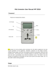
CONTENT Ⅰ Introduction ............................2 Ⅱ Function Characteristics ..................2 Ⅲ Technical Parameters Ⅳ Packet List ...................................... 3 ........................................................4 Ⅴ Components ................................................ 4 Ⅵ Installation and Connection .........................................4 Ⅶ The Description of Basic Operations ............................. 5 Ⅷ Introduction of GPRS Function (Optional) .........................10 1 Ⅰ Introduction Welcome to choose our product, which adopts fixed wireless industrial module and RINGSL IC module supporting GSM 850MHz/900MHz/1800 MHz/1900Mhz and it is also one kind of excellent fixed wireless communication terminal. It can be connected to exterior phone supporting GSM mobile communication service to realize the telecom service for normal phone with the features of high quality voice resolution, credible performance and it is suitable for remote district, local mobile public phone service, historic site place, museum, fane and many other places which are inconvenient for wired phones. In order to user the functions of this terminal normally, please read this user manual carefully before using it: Place it to a dry place to protect the interior components being affected with damp or other sundries enter into it to affect the conversation quality. Clear it by a little wet or defending static cloth, and do not use chemistry solvent or dry cloth to clear it. If there are some problems of it, laypeople do not open it. Please send it to the local maintain service place or contact with after sales service center of our company directly. This terminal supports GSM network, so it can be disturbed as other mobile phone. You should charge the backup Ni-MH battery for more than 20 hours when you use it first time and if the power is not enough, it may cause noise during conversations. Before changing or taking out the SIM card, please turn off the terminal. Use the authorized antenna, power adapter, and so on. Do not change or use the unsuitable fittings. Use this product in the places where the mobile phone can be used. Ⅱ Function Characteristics Supporting GSM 850MHz/1900MHz/900MHz/1800MHz Telecommunication Network. The LCD can support caller ID and will show the date, time number and other kinds of cursors and so on. Setting date, time and so on. Setting the delaying time for automatic dialing. Call barring function. Incoming calls indicator. Outgoing calls indicator. Sending call information (DTMF) Providing user IC and RINGSL signal. Supporting reverse polarity function. PIN code protection function. 2 Calls forward. Compatible with ARM voice coding way. Supporting PSTN function and switch the wireless or wired lines freely. Storing 10 groups incoming calls number. Storing 10 groups missed calls number. Storing 10 groups dialed calls number. Power indicator light. One connecting phone port. One PSTN port. Exterior power switch. Magnet antenna. Switching power supply. Ni-MH rechargeable battery. Supporting GRPS function. (optional) Ⅲ Technical Parameters Size: 200*140*55 mm (L*W*H) Weight: < 1K (including power adapter and battery) Installation: Horizontal Installation Power Adapter: AC 220V DC 5V 800mA Battery Specs: 3.6 1600mA Ni-MH battery Environmental Temperature: -10℃~40℃ Humidity:10%~95% Atmosphere Pressure: 86~106kpa Power Consumption: <100mA (in the idle state) Standby Time: more than 12 hours Talk Time: 2H Annotation: Talk time and standby time is according to the local network. Ⅳ Packet List One terminal One exteral antenna One power adapter One user manual One Ni-MH battery One P+P external down-lead cable One data cable (if this terminal has GPRS function, there will have this data cable or there will not have this 3 one.) Ⅴ Components 1:LCD 2:Signal indicator light 3:Power indicator light (Always being bright connected to external power adapter) 4:TEL1:Connect to one extension 5:TEL2:Connect to PSTN 6:POWER:Power switch (Placing it to “I” means “ON” and placing it to “0” means “OFF”) 7:Power port:Being used to connect to external power adapter 8:Transfer Switch:Move the switch to “MODEM” place when using the GPRS function or move the switch to “PHONE” place (If the terminal has this optional function, the terminal will have this switch) 9:Data port:Connect to data cable (If the terminal has this GPRS optional function, the terminal will have this port) Ⅵ Installation and Connection 1. The Installation of SIM card and Battery Open the battery cover of the host and the SIM card’s slot, and insert SIM card along indentation direction to make sure the contact is good, and then insert the battery to the interior battery jack and last close the battery cover. 2. The Installation of Antenna Connect one end of the magnet antenna to the right side port of the host and fasten it. Put the base seat of the magnet in a suitable place. 3. The Connection of Power Adapter Connect the power adapter to the city jack (rang 100-240V) and connect the pin of the power adapter to the phone. 4. Turn on 4 Move the switch of the host to the “I” place, and the power light indicator will be bright and the LCD will show indication. The terminal will enter into the idle state after initialization (several seconds). If the signal indicator light is flashing, it means the terminal takes service normally. You also can search the signal indicator icon on the LCD, and if the signal tree is less (total 5 signal trees), you can adjust the antenna’s place to get stronger signal. If the signal indicator light is bright all the times, it means the terminal can not take service normally. Please check whether the installation of the SIM card is right or wrong, and if this trouble also can not be solved, please contact to the local mobile supplier directly. 5. The Connection between the Terminal and Phone ⑴. Connect one end of the P+P external down-lead cable to either port “TEL 1”of the terminal, and connect the other end of the of P+P external down-lead cable to the normal phone and then if you pick up the handset, you can hear clear dialing sound, (the back light of the LCD will be bright waiting to be dialed) which means the connection is all right. Annotation: Please put the magnet antenna far away more than 1 meter from the terminal for if the distance is too close, the normal phone will be interfered causing the noise. ⑵. Connect the phone using PSTN network to the port “TEL 2” of the terminal to connect to PSTN network, which can realize using wireless or wired lines with one terminal. Ⅶ The Description of Basic Operations Please move the transfer switch to the "PHONE" place when you do the following operations. Parameters Setting You should set the terminal by phones and during the settings, the phone always in the off-hook state. If there is an incoming call, the terminal will refuse to answer it automatically but store the number as missed call. 1. The Key Definition of the phone ① “2”: “UP” key ② “8”: “DOWN” key ③ “4”: “UP” key ④ “6”: “CONFIRM” key ⑤ “*”: “EXIT” key ⑥ “#”: “SET/CONFIRM” key 5 2. Descriptions of Setting Menu ■ SET 1 DATE Set Date ■ SET 2 DELAY DL Set the delay dialing automatic time ■ SET 3 INCO_ING Set allow to receive incoming calls or not 3. Setting Operations 1) Setting Date and Time Press “#” key more than 2 seconds or input “###***” and the LCD will show “SET 1 DATE”. Press “#” key and the LCD will show “DT XXXXXXXXXX” and input 10 date data (the mode is year year, month month, day day, hour hour, minute minute), and then press “#” key to confirm it. At the same time, the LCD will show: “PASS”, which means that this operation is correct, and it will return to the former menu automatically. “FAIL”, which means that this operation is wrong, and it will return to the current date, so the user can set it again. 2) Setting Delaying Time for Automatic Dialing Press “#” key more than 2 seconds or input “###***” and the LCD will show “SET 1 DATE”, and then press “2” key or “*” key to search “SET 2 DELAY DL”. Press “#” key or “6” key and the LCD will show “DELAY DIAL XX” and input 1~2 digitals (range is “3~20” and the unit is second), and press “#” key to confirm it. At this time the LCD will show: “PASS”, which means that this operation is correct, and it will return to the former menu automatically. “FAIL”, which means that this operation is wrong, and it will return to the current setting, so the user can set the “DELAY DIALING” again. Annotation: The terminal will send the number from phones according to the set delaying time and the initial delaying time is 5 seconds. 3) Setting Call Barring Press “#” key more than 2 seconds or input “###***” and the LCD will show “SET 1 DATE”, and then press “8” key or “*” key to search “SET 3 INCO_ING”. Press “#” key or “6” key and the LCD will show “INCOMING ON” (the initial state is allowed incoming calls state.) If you input “0”, it means you want to forbid the incoming calls, the LCD will show “INCOMING OFF”; if you input “1”, it means you allow the incoming calls, the LCD will show “INCOMING ON” and press “#” key to confirm it. At this time the LCD will show: “PASS”, which means that this operation is correct, and it will return to the former menu automatically. 6 Using PIN Code Protection 1. Open PIN Code Protection Function Pick up the handset and input “***65*1+initial PIN code+#”. If the LCD shows “PASS”, it means you have open this function and if the LCD shows “FAIL”, it means this setting fails and you should input it again. The LCD will show “ERR CARD PIN” after you turn on the phone if you have open PIN code protection function, which needs you to pick up the handset and input “***63*+PIN code+#”. (The initial PIN code is 1234). If you input the correct PIN code, the phone will check itself and then enter into the idle state. If you have input wrong PIN code thrice after you turn on the phone, the LCD will shows “ERR CARD PUK”, which needs you to input PUK code—“***64*+PUK+*+new PIN code+#”. After you input the right code, the phone will check itself and then enter into the idle state. Attention: Please do remember the PIN code and PUK code or the phone can not take service normally, which will bring inconvenience to you. 2. Close the PIN Code Protection Function Pick up the handset and input “***65*0*+initial PIN code+#”. If the LCD shows “PASS”, it means you have close this function; if the LCD shows “FAIL”, it means this setting fails and you should input it again. Changing PIN Code Pick up the handset and input “***61*+initial PIN code*new PIN code#”. If the LCD shows “PASS”, it means you have change the PIN code; if the LCD shows “FAIL”, it means this setting fails and you should set it again. Annotation: You can change the PIN code only after you have open the PIN code protection function and please remember your new PIN code. Search the Incoming and Outgoing Calls, Dial Back, Delete You can search the missed calls, answered calls, and dialed calls and delete or dial back, and the operations are as the followings: ■ Pick up the handset, and press “*” key more than 2 seconds or input “***###” and wait for more than 2 seconds. The LCD will show “CALLLIST” with the following 3 submenu: 1. CALL LOST (Searching the missed calls of the phone) 2. CALL OUT (Searching the outgoing calls of the phone) 3. CALL IN (Searching the answered calls of the phone) ■ Press “#” (CONFIRM) key to search calls records directly or press “*” (DOWN) key to search the next item and 7 press “#” key to confirm and enter into it. ■ Press “#” key, the LCD will show the first call record and you can do the following operations at this time: Press “2” key: Up to check. Press “8” key: Down to check. Press “4” key: Search the talking time and date. Press “6” key: Search how much time this conversation use. Press “0” key: Press this key twice to delete the current record and turn to next one automatically. Press “9” key: Dial back the current and exit the searching state. Call Transfer Call transfer function allows you to transfer one type call to another appointed phone in the pre-set condition. You can set All Transfer, Busy Transfer, No Answer within 20 seconds Transfer, Not found Transfer in this phone. Please contact with your network carrier to open this service: 1. All Transfer: Transfer the calls in any conditions. Pick up the handset and input “***30*appointed phone number#”. If the LCD shows “PASS”, it means All Transfer setting is successful; if the LCD shows “FAIL”, it means this setting fails and you should set it again. If you want to cancel this function, you can input “***30*#”. If the LCD shows “PASS”, it means All Transfer setting is canceled; if the LCD shows “FAIL”, it means this setting fails and you should set it again. 2. Busy Transfer: Transfer when the phone is on. Pick up the handset and input “***31*appointed phone number#”. If the LCD shows “PASS”, it means Busy Transfer setting is successful; if the LCD shows “FAIL”, it means this setting fails and you should set it again. If you want to cancel this function, you can input “***31*#”. If the LCD shows “PASS”, it means Busy Transfer setting is canceled; if the LCD shows “FAIL”, it means this setting fails and you should set it again. 3. No Answer within 20 seconds Transfer: Transfer when there is no one to answer the phone within 20 seconds. Pick up the handset and input “***32*appointed phone number#”. If the LCD shows “PASS”, it means No Answer within 20 Seconds Transfer setting is successful; if the LCD shows “FAIL”, it means this setting fails and you should set it again. If you want to cancel this function, you can input “***32*#”. If the LCD shows “PASS”, it means No Answer within 20 Seconds Transfer setting is canceled; if the LCD shows “FAIL”, it means this setting fails and you should set it again. 4. Not Found Transfer: Transfer when this phone can not be connected to. 8 Pick up the handset and input “***33*appointed phone number#”. If the LCD shows “PASS”, it means Not Found Transfer setting is successful; if the LCD shows “FAIL”, it means this setting fails and you should set it again. If you want to cancel this function, you can input “***33*#”. If the LCD shows “PASS”, it means Not Found Transfer setting is canceled; if the LCD shows “FAIL”, it means this setting fails and you should set it again. 5. All Transfers: All Transfer, Busy Transfer, No Answer within 20 seconds Transfer; Not Found Transfer. Pick up the handset and input “***34*appointed phone number#”. If the LCD shows “PASS”, it means All Transfers setting is successful; if the LCD shows “FAIL”, it means this setting fails and you should set it again. If you want to cancel this function, you can input “***34*#”. If the LCD shows “PASS”, it means All Transfers setting is canceled; if the LCD shows “FAIL”, it means this setting fails and you should set it again. 6. Last Three Transfers at the same time: Busy Transfer, No Answer within 20 seconds Transfer; Not Found Transfer. Pick up the handset and input “***35*appointed phone number#”. If the LCD shows “PASS”, it means Last Three Transfers setting is successful; if the LCD shows “FAIL”, it means this setting fails and you should set it again. If you want to cancel this function, you can input “***35*#”. If the LCD shows “PASS”, it means Last Three Transfers setting is canceled; if the LCD shows “FAIL”, it means this setting fails and you should set it again. Ⅷ Introduction of GPRS Function (Optional) Please move the transfer switch to the "MODEN" place when you do the following operations. Preparations 1. Configurations One terminal, one antenna, one data cable, one external power adapter (if you use external power adapter to supply power), one SIM card and one PC. (Operating System is: Windows98, Windows 2000 or Windows XP). 2. Connection Insert SIM card: Open the battery cover and the SIM card slot and insert SIM card along the indentation and last then close the battery cover. (Make sure the terminal is in the turn-off state when you insert the SIM card.) Connecting to the External Power Adapter and the antennal: Insert one end of the power adapter to the city power jack and insert the other end to the power port of the terminal. The power indicator light will be bright always and connect antenna to the terminal. Connecting to PC: Connect one end of the data cable to the COM port of the PC and connect the other end of the data cable to the data port of the terminal. 3. Turn On 9 Place the power switch of the terminal to the place of “1” and the terminal will enter into the idle state after checking itself. Place the transfer switch of the place of “MODEM” to switch the terminal to the internet state and the LCD of the terminal will show “PC”. Please move the transfer switch to the "PHONE" place and pull off the data cable if you want to exit the internet state. Installation of the MODEM 1. Open “Control Panel” and choose “Phone and Modem options”, Figure 1: Figure 1 2. Click “Phone and Modem Options” twice and it will come out the “Phone and Modem Options”” window. Choose “Modems”, Figure 2: Figure 2 3. Click “ADD” to add new modem and it will come out “Installing New Modem”, Figure 3: 10 Figure 3 4. Choose “Do not detect my modem; I will select it from a list” and then click “Next”, it will show Figure 4 Figure 4 5. Choose “Standard Modem Type” as Manufacturer and choose “Standard 33600 bps” as model. Click “Next” and it will come out the Figure 5: Figure 5 6. Choose the COM port (often to choose COM1) and click “Next”. It will come out Figure 6: 11 Figure 6 7. Click “Finish” to complete the installation and it will come out the Figure 7: Figure 7 8. Click the Properities of the modem that you just have installed and open the “MODEM” item to set the speed as “38400” for the Max. Port Speed, (Figure 8) and press “OK”. Figure 8 9. Open “ADVANCED” item and input AT+CGDCONT=1, “IP”, “CMNET” in the “Extra Initialization Commands”, Figure 9. (This point is very important and you have to set the initial order) 12 Figure 9 9. Click “Change Default Preferences” button and then set Port Speed as “38400” and Data Flow Control as “None”, Figure 10: Figure 10 10. Click “OK” to finish the installation of Modem。 Building the Dialing Connection for this New Modem 1. Open “Network Connections” in the “Control Panel” and click “Create a New Connection”. Click “Next”. 2. Choose “Connect to Internet” and click “Next”. 3. Choose “Set up My Connection Manually” and click “Next”. 4. Choose “Connec use a Dial-up modem” and click “Next”. 5. Input ISP name, such as GPRS, and then press “Next”, Figure 11. 13 Figure 11 6. Input the code such as “*99***1#” provided by operator in the “Phone Number” after it come out the “New Connection Wizard”, Figure 12 and then click “Next”. Figure 12 7. Set the Internet account information as the Figure 13 and click “Next”. Figure 13 8. Click “Finish” button to finish the connection, Figure 14. 14 Figure 14 Dialing Number to Get to Internet 1. Open the “Network Connections” in “Control Panel” and click the name you just have build (GPRS) to open the following new connection window, Figure 15. Figure 15 2. Click “Properties” and choose “GENERAL” after coming out the Figure 16. Figure 16 3. Click “Configuration” button and do the settings as the Figure 17 and then click “OK” to go on. 15 Figure 17 4. Choose “Networking” and click “Settings” button to do the following settings as Figure 18. Click “OK” button to finish this setting. Figure 18 5. Return to the Figure 19 state and click “Dial” button to get to Internet. Figure 19 16 Troubleshooting 1. When Dialing Number, but it is failed, Why? Answer: There are the following possible reasons and the customer should judge one by one: (A) The single is weak in your local area, so the GPRS MODEM can not receive the signal by mobile communication; (B) Whether the communication network has this service or not; (C) The SIM card is not insert well; (E) The account of the SIM card doesn’t have enough money and is stopped service; (F) The SIM card doesn’t have this GPRS service; (G) You use the special GPRS SIM card and the card have not been activated. 2. If the phone can not take service after you use the INTERNET function, what should you do? Answer: Move the switch to the place of “PHONE” and pull out the data cable, and then you can make calls. 17 GSM Fixed Wireless Terminal User Manual 18