1
Operating System Manual
rcX - Realtime Communication System for netX
Configuration of rcX
V2.0/2.1
Hilscher Gesellschaft für Systemautomation mbH
www.hilscher.com
DOC050601OS08EN | Revision 8 | English | 2013-06 | Released | Public
Introduction
2/94
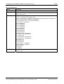
Table of Contents
1
Introduction.............................................................................................................................................4
1.1 About this Document......................................................................................................................4
1.2 List of Revisions .............................................................................................................................4
1.3 Legal Notes ....................................................................................................................................5
1.3.1
1.3.2
1.3.3
1.3.4
Copyright ........................................................................................................................................... 5
Important Notes................................................................................................................................. 5
Exclusion of Liability .......................................................................................................................... 6
Export ................................................................................................................................................ 6
2
Configuring rcX ......................................................................................................................................7
2.1 A Single Source Code-File (Config.c) for the Configuration ..........................................................7
2.2 List of configurable Resources and Peripherals ............................................................................7
2.3 The Behavior after a System Reset ...............................................................................................8
2.4 The Application-Entry Code .........................................................................................................10
2.5 The Location of the main() Function to Enter the Kernel .............................................................11
3
System Configuration Data Structure ................................................................................................13
3.1 Configure Drivers using RX_DRIVER_PERIPHERAL_CONFIG_T.............................................15
3.2
3.1.1 The RX_DRIVER_PERIPHERAL_CONFIG_T Structure Reference ............................................... 15
Loading Middleware Modules using tMiddleware ........................................................................17
3.2.1 The RX_MIDDLEWARE_CONFIG_T Structure Reference ............................................................. 17
4
Defining the Application-Tasks...........................................................................................................18
4.1 The RX_STATIC_TASK_T Structure Reference .........................................................................18
5
Configuring the Hardware Platform and the Resources ..................................................................22
5.1 The Peripheral Configuration Table in General ...........................................................................22
5.2 Default Resource Configuration ...................................................................................................23
5.3 Defining the Hardware in Peripheral Objects...............................................................................24
5.4
5.5
5.6
5.7
5.8
5.9
5.3.1 The RX_PERIPHERAL_HEADER_T Peripheral Object Header Structure...................................... 25
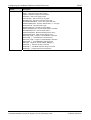
Configuring the Trace Memory Pool ............................................................................................27
5.4.1 The RX_TRACE_SET_T Trace Memory Object Structure Reference............................................. 28
Configuring the Hardware Interrupts............................................................................................29
5.5.1 The RX_INTERRUPT_SET_T Interrupt Object Structure Reference .............................................. 29
Configuring Hardware Timers and Counters ...............................................................................33
5.6.1 The RX_HWTIMER_SET_T Hardware Timer/Counter Object Structure Reference ....................... 34
Configuring the UARTs ................................................................................................................36
5.7.1 The RX_UART_SET_T UART Object Structure Reference ............................................................ 37
Configuring the SRAM Bus ..........................................................................................................41
5.8.1 The RX_SRAMBUS_SET_T SRAM Bus Configuration Structure Reference................................. 42
Configuring Parallel FLASH .........................................................................................................44
5.9.1 The RX_PARALLELFLASH_SET_T Parallel FLASH Object Structure Reference......................... 45
5.10 Configuring Serial Peripheral Interface (SPI)...............................................................................48
5.10.1 The RX_SPISLAVE_SET_T SPI Object Structure Reference........................................................ 49
5.11 Configuring Serial FLASH ............................................................................................................51
5.11.1 The RX_SERIALFLASH_SET_T Serial Flash Object Structure Reference.................................... 52
5.12 Configuring the Ethernet PHY Transceivers ................................................................................56
5.12.1 The RX_PHY_SET_T Ethernet PHY Transceiver Object Structure Reference ............................... 57
5.13 Configuring the General-Purpose I/Os (GPIOs) ..........................................................................59
5.13.1 The RX_GPIO_SET_T General Purpose I/O Object Structure Reference ..................................... 60
5.14 Configuring the Programmable I/Os (PIOs) .................................................................................63
5.14.1 The RX_PIO_SET_T Programmable I/O Object Structure Reference ........................................... 63
5.15 Configuring the HIF Programmable Input/Output pins.................................................................66
5.15.1 The RX_HIFPIO_SET_T Host Interface PIO Object Structure Reference....................................... 66
5.16 Configuring the General I/Os (IOs) ..............................................................................................68
5.16.1 The RX_IO_SET_T General I/O Object Structure Reference......................................................... 68
5.17 Configuring the Extended Fieldbus Controllers (xC) ...................................................................69
5.17.1 The RX_XC_SET_T Extended Controller Object Structure Reference .......................................... 70
5.18 Configuring the Media Volumes...................................................................................................72
5.18.1 The RX_VOLUME_SET_T Volume Object Structure Reference..................................................... 72
5.19 Configuring the Host Interface .....................................................................................................75
5.19.1 The RX_HIF_SET_T Host Interface Object Structure Reference.................................................... 76
5.20 Configuring the FIFO Channels ...................................................................................................81
rcX - Realtime Communication System for netX | Configuration of rcX
DOC050601OS08EN | Revision 8 | English | 2013-06 | Released | Public
© Hilscher, 2005-2013
Introduction
3/94
5.20.1 The RX_FIFOCHANNEL_SET_T Host Interface Object Structure Reference ................................ 81
5.21 Configuring the LEDs ...................................................................................................................83
5.21.1 The RX_LED_SET_T LED Object Structure Reference .................................................................. 83
5.22 Configuring the Ethernet Interfaces .............................................................................................88
5.22.1
5.22.2
5.22.3
5.22.4
6
The RX_EDD_SET_T Ethernet Object Structure Reference........................................................... 88
Parameters in RX_EDD_PARAMETERS_T.................................................................................... 90
Using Multiple Interfaces ................................................................................................................. 91
Examples of Ethernet Object Templates ......................................................................................... 91
Appendix ...............................................................................................................................................93
6.1 List of Tables................................................................................................................................93
6.2 Contacts .......................................................................................................................................94
rcX - Realtime Communication System for netX | Configuration of rcX
DOC050601OS08EN | Revision 8 | English | 2013-06 | Released | Public
© Hilscher, 2005-2013
Introduction
1
1.1
4/94
Introduction
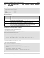
About this Document
This manual describes configuration of rcX within the “Config.c” file.
1.2
List of Revisions
Rev
Date
Name
Chapter
Revision
8
2013-06-20
SP
5.21.1
3
5.16
Example for LED on HifPIO configuration updated.
rcX V2.1 specific kernel initialization (Scheduler, Cache) added.
rcX V2.1 specific general I/O driver added.
rcX V2.1 specific I/O driver support included.
Table 1: List of Revisions
rcX - Realtime Communication System for netX | Configuration of rcX
DOC050601OS08EN | Revision 8 | English | 2013-06 | Released | Public
© Hilscher, 2005-2013
Introduction
1.3
1.3.1
5/94
Legal Notes
Copyright
© Hilscher, 2005-2013, Hilscher Gesellschaft für Systemautomation mbH
All rights reserved.
The images, photographs and texts in the accompanying material (user manual, accompanying
texts, documentation, etc.) are protected by German and international copyright law as well as
international trade and protection provisions. You are not authorized to duplicate these in whole or
in part using technical or mechanical methods (printing, photocopying or other methods), to
manipulate or transfer using electronic systems without prior written consent. You are not permitted
to make changes to copyright notices, markings, trademarks or ownership declarations. The
included diagrams do not take the patent situation into account. The company names and product
descriptions included in this document may be trademarks or brands of the respective owners and
may be trademarked or patented. Any form of further use requires the explicit consent of the
respective rights owner.
1.3.2
Important Notes
The user manual, accompanying texts and the documentation were created for the use of the
products by qualified experts, however, errors cannot be ruled out. For this reason, no guarantee
can be made and neither juristic responsibility for erroneous information nor any liability can be
assumed. Descriptions, accompanying texts and documentation included in the user manual do
not present a guarantee nor any information about proper use as stipulated in the contract or a
warranted feature. It cannot be ruled out that the user manual, the accompanying texts and the
documentation do not correspond exactly to the described features, standards or other data of the
delivered product. No warranty or guarantee regarding the correctness or accuracy of the
information is assumed.
We reserve the right to change our products and their specification as well as related user
manuals, accompanying texts and documentation at all times and without advance notice, without
obligation to report the change. Changes will be included in future manuals and do not constitute
any obligations. There is no entitlement to revisions of delivered documents. The manual delivered
with the product applies.
Hilscher Gesellschaft für Systemautomation mbH is not liable under any circumstances for direct,
indirect, incidental or follow-on damage or loss of earnings resulting from the use of the information
contained in this publication.
rcX - Realtime Communication System for netX | Configuration of rcX
DOC050601OS08EN | Revision 8 | English | 2013-06 | Released | Public
© Hilscher, 2005-2013
Introduction
1.3.3
6/94
Exclusion of Liability
The software was produced and tested with utmost care by Hilscher Gesellschaft für
Systemautomation mbH and is made available as is. No warranty can be assumed for the
performance and flawlessness of the software for all usage conditions and cases and for the
results produced when utilized by the user. Liability for any damages that may result from the use
of the hardware or software or related documents, is limited to cases of intent or grossly negligent
violation of significant contractual obligations. Indemnity claims for the violation of significant
contractual obligations are limited to damages that are foreseeable and typical for this type of
contract.
It is strictly prohibited to use the software in the following areas:
for military purposes or in weapon systems;
for the design, construction, maintenance or operation of nuclear facilities;
in air traffic control systems, air traffic or air traffic communication systems;
in life support systems;
in systems in which failures in the software could lead to personal injury or injuries leading to
death.
We inform you that the software was not developed for use in dangerous environments requiring
fail-proof control mechanisms. Use of the software in such an environment occurs at your own risk.
No liability is assumed for damages or losses due to unauthorized use.
1.3.4
Export
The delivered product (including the technical data) is subject to export or import laws as well as
the associated regulations of different counters, in particular those of Germany and the USA. The
software may not be exported to countries where this is prohibited by the United States Export
Administration Act and its additional provisions. You are obligated to comply with the regulations at
your personal responsibility. We wish to inform you that you may require permission from state
authorities to export, re-export or import the product.
rcX - Realtime Communication System for netX | Configuration of rcX
DOC050601OS08EN | Revision 8 | English | 2013-06 | Released | Public
© Hilscher, 2005-2013
Configuring rcX
2
2.1
7/94
Configuring rcX
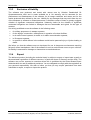
A Single Source
Configuration
Code-File
(Config.c)
for
the
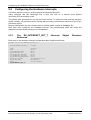
The goal of the “Config.c” file is to have the configuration of the kernel and drivers in a central
location.
Additionally, this is meant to remove the burden of recompiling either the kernel or driver modules
on compatible hardware platforms and increase the flexibility of the already compiled libraries.
The content of the “Config.c” file is defined by a header file called “rX_Config.h”. Within this file,
you find all relevant structures and definitions, described in the following chapters of this manual.
However, the name of the “Config.c” file is not specifically defined and can be changed to suit your
needs.
2.2
List of configurable Resources and Peripherals
The following resources and peripherals are configurable within the “Config.c” file:
Application tasks, stack, entry and leave function.
Hardware interrupts, trigger mode, priority and reentrancy.
Timer, re-load value and operational mode.
UART, baud-rate and character settings.
Host interface, sizes and memory locations.
Parallel FLASH, device ID, type and sectors.
Serial FLASH, sizes and instruction commands.
SPI (Serial Peripheral Interface), port number, baud-rate and slave chip select.
SRAM bus, wait-states and chip-selects.
PHY (Ethernet Transceivers), port location and port number for the MDIO bus.
Hardware Watchdog, port location and ret-rigger period.
GPIO (General Purpose I/O Pins), port addresses and direction.
xC (Extended Controller), address of the microcode to load
Trace pool, sizes and memory locations.
Firmware name and version string.
Furthermore, it is possible to extend the "Config.c" file using your own definitions and
configuration tables.
rcX - Realtime Communication System for netX | Configuration of rcX
DOC050601OS08EN | Revision 8 | English | 2013-06 | Released | Public
© Hilscher, 2005-2013
Configuring rcX
2.3
8/94
The Behavior after a System Reset
Once the CPU is performing a reset – no matter what type of reset it is - the address of the initial
code, to be started, is retrieved from a well-defined memory location.
For the netX-CPU, this is the standard ARM©-Processor reset vector located at the memory
address 0x00000000. The CPU transfers the control to that code location automatically after the
value of the entry point has been retrieved. If the physical memory at this position consists of a
traditional non-volatile storage device, like a parallel FLASH or an EEPROM, the entry code is
changeable and the rest of the memory delivers the application code implicitly.
The reset solution within the netX differs from the traditional method. Unlike most ARM-based
CPUs, the internal SRAM memory banks are starting from address 0x00000004. Since RAM is
volatile and the data in it does not survive a power-on reset, booting in the traditional way would
not be possible.
Therefore, in the netX, the ARM© entry point value at address 0x00000000 is hard-coded and not
changeable. This forces the CPU to always jump to an address within the permanent ROM
memory, starting at address 0x200000. By jumping to this hard-coded memory location, the first
stage boot loader code is started.
The first stage loader (ROM loader) is checking the different boot media e.g. parallel or serial
FLASH whether it can find an application-code to be loaded. Detection of a bootable image is
based on a 64 byte header (BOOTBLOCK), which informs the loader about the load address and
the entry point of the application-code. The code will be copied to the defined memory location and
a jump to the specified entry point is executed.
rcX - Realtime Communication System for netX | Configuration of rcX
DOC050601OS08EN | Revision 8 | English | 2013-06 | Released | Public
© Hilscher, 2005-2013
Configuring rcX
9/94
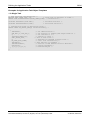
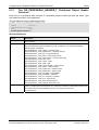
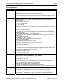
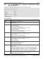
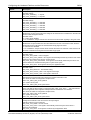
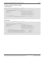
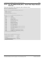
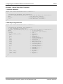
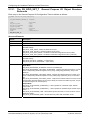
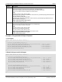
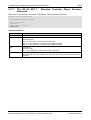
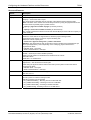
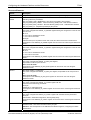
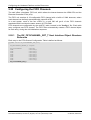
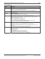
Definition of the 64 Byte Boot Header
Data Type
Name
Description
UINT32
ulMagCookie
0xF8BEAF00 or 0xF8BEAF08 or 0xF8BEAF16
UINT32
unCtrl
- Parallel/serial FLASH mode, timing parameters
- or I2C/SPI mode device speed settings
- or reserved in DPM / PCI mode
UINT32
ulApplEntrypoint
Application entry point
UINT32
ulApplChecksum
Application checksum
UINT32
ulApplSize
Application file size in DWORDs
UINT32
ulApplStartAddr
Application start address
UINT32
ulSignature
Signature = "NETX"
UINT32
unCtrl0
- SDRam general control value
- Expansion bus register value (EXPBus Bootmode)
UINT32
unCtrl1
- SDRam timing control register value
- IORegmode0 register value (EXPBus Bootmode)
UINT32
unCtrl2
- IORegmode1 register value (EXPBus Bootmode)
- or unused/reserved
UINT32
unCtrl3
- IfConfig1 register value (EXPBus Bootmode)
- or unused/reserved
UINT32
unCtrl4
- IfConfig2 register value (EXPBus Bootmode)
- or unused/reserved
UINT32
ulMiscAsicCtrl
ASIC CTRL register value
UINT32
ulSerial
Serial number
UINT32
ulSrcType
Source type
UINT32
ulBootChecksum
Boot block checksum
Table 2: Definition of the 64 Byte Boot Header
rcX - Realtime Communication System for netX | Configuration of rcX
DOC050601OS08EN | Revision 8 | English | 2013-06 | Released | Public
© Hilscher, 2005-2013
Configuring rcX
2.4
10/94
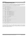
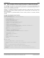
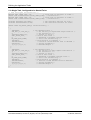
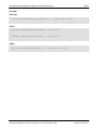
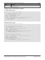
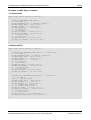
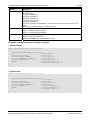
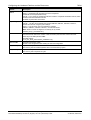
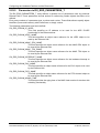
The Application-Entry Code
The code, which is located at the application entry point, is typically written in plain assembler
language and contains the development tool specific coding for assembler files. Within the rcX,
there are specific versions of the entry code for the different CPU types and development tools. For
the netX CPU, the entry assembler code file is named “Init.s” and looks like:
# --- Save the bootblock -----------------------------start:
LDR r2, =ulBootOption
STR r1, [r2]
LDR
R1, =tBootblock
LDR
R2, =tBootblock + 64
LoopBoot: CMP
R1, R2
LDRLO
R3, [R0], #4
STRLO
R3, [R1], #4
BLO
LoopBoot
# --- Initialize the different stack types ----------LDR
r0, =top_of_stacks
MSR
CPSR_c, #Mode_FIQ|I_Bit|F_Bit
SUB
sp, r0, #Offset_FIQ_Stack
MSR
CPSR_c, #Mode_IRQ|I_Bit|F_Bit
SUB
sp, r0, #Offset_IRQ_Stack
MSR
CPSR_c, #Mode_SVC|I_Bit|F_Bit
SUB
sp, r0, #Offset_SVC_Stack
MSR
CPSR_c, #Mode_SYS|I_Bit|F_Bit
SUB
sp, r0, #Offset_SYS_Stack
SUB
r1, r0, #Offset_Topof_Stack
# --- Fill the Stack with a pattern ------------------LDR
r2, =0xDEADBEEF
LoopSt:
CMP
r1, r0
STRLO
r2, [r1], #4
BLO
LoopSt
# --- Clear .bss section (Zero init) -----------------MOV
R0, #0
LDR
R1, =__bss_start__
LDR
R2, =__bss_end__
LoopZI:
CMP
R1, R2
STRLO
R0, [R1], #4
BLO
LoopZI
# --- Jump to the main function ----------------------LDR
r0, =main
BX
r0
The low-level initialization code is used to initialize the basic environment that comes along with
the used GNU Compiler development tools. This includes the initialization of the zero-initialized
global variables and the CPU specific initialization of the stack(s). Finally, this code includes the
jump to the user-supplied main() function.
rcX - Realtime Communication System for netX | Configuration of rcX
DOC050601OS08EN | Revision 8 | English | 2013-06 | Released | Public
© Hilscher, 2005-2013
Configuring rcX
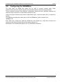
2.5
11/94
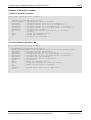
The Location of the main() Function to Enter the Kernel
The "Config.c" file contains the main() function. At this point you can control what happens next
with your code. Typically, the main() function simply calls the rX_SysEnterKernelExt() function in
order to start the operating system (OS).
However, it is allowed to process user specific code prior to enter the kernel. This could be
necessary if some specific hardware settings must be executed before the actual jump to the
kernel is performed.
The pre-compiled rX_SysEnterKernelExt() function normally includes all necessary hardware
settings.
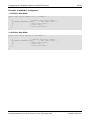
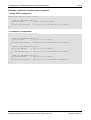
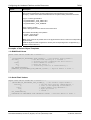
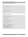
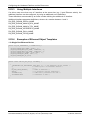
Example of the Standard main() Function:
RX_ENTER_KERNEL_PARAM_T
CONST RX_ENTERKERNEL_PARAM_T trXEnterKernelParam=
{
/* CPU clock rate */
NETX_FREQUENCY_100MHZ,
/* Timer interrupt task priority */
{TSK_PRIO_DEF_RX_TIMER, 350},
/* Pointer to static Task-List */
{atrXStaticTasks, MAX_CNT(atrXStaticTasks)},
/* Pointer to rx kernel modules list */
{0, 0},
/* Pointer to the Peripherals-List */
{atrXCfg, MAX_CNT(atrXCfg)},
/* Pointer to the Post Peripherals-List / LoadDrivers included into */
{atrXDrvCfgPost, MAX_CNT(atrXDrvCfgPost)},
/* Pointer to optional Jump Table */
{NULL, 0},
/* Callback for special initialization */
NULL,
/* Pointer to the Middleware List */
{atMidCfgTbl, MAX_CNT(atMidCfgTbl)},
/* Scheduler component (if another scheduler is desired) */
0,
/* Cache enable flags */
{TRUE, TRUE},
/* Disable Idle measurement */
{TRUE},
/* Early Callback */
NULL,
/* MMU Translation Table address */
{0x10000}
};
INT main (void)
{
volatile RX_FATAL erXFat; /* Fatal Error value */
/* Initialize and boot the Kernel, with all Peripherals listed in the parameter
* block
*/
erXFat = rX_SysEnterKernelExt(&trXEnterKernelParam);
/* Loop forever here, to keep the "erXFat" variable debug able */
while(1==1);
/* Prevent the compiler warning because of non-void returning main-function */
return(0);
}
rcX - Realtime Communication System for netX | Configuration of rcX
DOC050601OS08EN | Revision 8 | English | 2013-06 | Released | Public
© Hilscher, 2005-2013
Configuring rcX
12/94
The kernel initialization process is started by calling rX_SysEnterKernelExt(). The function will
check the configuration consistency.
In comparison to other embedded Operating Systems, the rcX may return from that function
whether it has detected a so-called fatal error or not.
In case of an error, the main() function remains in an endless while() loop stopping the code
execution right after rX_SysEnterKernelExt(). This allows the checking of the return code in the
variable erXFat by using a debugger.
The definitions of the fatal error codes can be found in the “rX_Fatal.h” header file.
rcX - Realtime Communication System for netX | Configuration of rcX
DOC050601OS08EN | Revision 8 | English | 2013-06 | Released | Public
© Hilscher, 2005-2013
System Configuration Data Structure
3
13/94
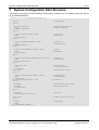
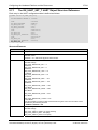
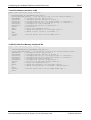
System Configuration Data Structure
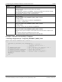
This structure provides all the necessary information to initialize the rcX system during the call to
rX_SysEnterKernelExt().
typedef struct RX_ENTERKERNEL_PARAM_Ttag
{
UINT32
struct
{
RX_TASK_PRIORITY
UINT
} tTimerTaskConfig;
struct
{
CONST RX_STATIC_TASK_T FAR*
UINT
} tStaticTasks;
struct
{
CONST RX_KERNEL_MODULES_T FAR*
UINT
} tKernelModules;
struct
{
CONST RX_PERIPHERAL_CONFIG_T FAR*
UINT
} tPeripherals;
struct
{
CONST RX_DRIVER_PERIPHERAL_CONFIG_T FAR*
UINT
} tDriverPeripherals;
struct
{
void FAR* FAR*
UINT
} tJumpTable;
void (FAR*
struct
{
CONST RX_MIDDLEWARE_CONFIG_T FAR*
UINT
} tMiddleware;
RX_SCHEDULER_FUNCTIONS_T FAR*
struct
{
BOOLEAN
BOOLEAN
} tCacheConfig;
struct
{
BOOLEAN
} tMeasureIdlePerformance;
void (FAR*
struct
{
UINT32
} tMMU;
} RX_ENTERKERNEL_PARAM_T;
ulCpuClkRate;
eTimerIrqTaskPriority;
uTimerStackSize;
patStatTsk;
uNumOfTsk;
patEntries;
uNumOfEntries;
patPer;
uNumOfPer;
patDrvPer;
uNumOfDrvPer;
ppvJumpTable;
uSizeOfJumpTable;
pfnCallBack)(void);
ptMidCfgTable;
uNumOfMidCfg;
ptScheduler;
fEnableInstructionCache;
fEnableDataCache;
fDisable;
pfnEarlyCallback)(void);
ulPhysAddr;
rcX - Realtime Communication System for netX | Configuration of rcX
DOC050601OS08EN | Revision 8 | English | 2013-06 | Released | Public
© Hilscher, 2005-2013
System Configuration Data Structure
14/94
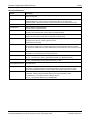
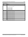
Structure Elements
Element
Description
ulCpuClkRate
Definition of the system clock frequency given in [Hz]
(cycles per second)
tTimerTaskConfig
Timer Task Configuration.
eTimerIrqTaskPriority - defines the Timer task priority (like for any other task).
uTimerStackSize - defines the number of stack elements and has a fixed value of 350.
tStaticTasks
Static Task Table
tKernelModules
Table of Additional Kernel Modules.
Used for already-compiled libraries.
tPeripherals
Kernel Peripheral Table.
Containing the hardware timer and the interrupt peripheral tables.
tDriverPeripherals
Driver Peripheral Table.
Used for all other drivers (except the two provided by tPeripherals).
tJumpTable
OS Function Patch Jump Table.
The table can be used to override system functions.
(Initialized to 0 if not used).
pfnCallback
User Initialization Callback Function.
This function is called by the rcX kernel just before the specified static tasks are created.
Can be used for additional user system initialization functions like format the FAT file system
etc.
tMiddleware
Structure of the RX_MIDDLEWARE_CONFIG_T table.
This table is used to initialize the rcX system services.
ptScheduler
rcX V2.0 – Not implemented (must be NULL).
rcX V2.1 – Must be set to either g_tMLQueueScheduler or g_tBitmapScheduler
tCacheConfig
rcX V2.0 – Not implemented (cache initialization is internally handled by the rcX)
rcX V2.1 – Must be setup for netX chips which have a cache
tMeasureIdlePerformanc Not implemented
e
pfnEarlyCallback
OS Specific Startup Callback Function.
The function is called after the kernel module initialization and can be used for system
specific pre-initialization functions of OS modules, while system drivers are not active.
tMmu
Memory Management Unit (MMU) Configuration Structure.
ulPhysAddr - defines the physical start address of the MMU translation table.
On ARM926EJ-S, this address must be 16kByte aligned.
rcX V2.1 : Use physical address of 0 to disable MMU
rcX - Realtime Communication System for netX | Configuration of rcX
DOC050601OS08EN | Revision 8 | English | 2013-06 | Released | Public
© Hilscher, 2005-2013
System Configuration Data Structure
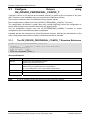
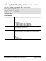
3.1
15/94
Configure
Drivers
RX_DRIVER_PERIPHERAL_CONFIG_T
using
n general, a driver in rcX requires to be installed, before it is usable by the rcX system or any user
task. Therefore, each installable driver must provide an initialization function.
This function is called by the rcX initialization during system startup.
Driver configuration is based on the RX_DRIVER_PERIPHERAL_CONFIG_T structure.
The configuration file defines a global data array (atrXDrvCfgPost[]) where the configuration is
stored. Each element in the structure describes one specific driver.
The rcx initialization function uses the RX_ENTERKERNEL_PARAM_T structure to locate
configuration data of the different system components.
Loadable drivers are referenced by tDriverPeripherals element, defining the start address of the
driver configuration table and the number of elements included in the table.
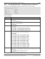
3.1.1
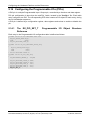
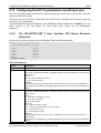
The RX_DRIVER_PERIPHERAL_CONFIG_T Structure Reference
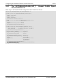
typedef struct RX_DRIVER_PERIPHERAL_CONFIG_Ttag
{
RX_FATAL (*
pfnDrvInit) (CONST void* pvCfg,UINT uNum);
RX_PERIPHERAL_TYPE eTyp;
CONST void FAR*
pvPer;
UINT
uNum;
} RX_DRIVER_PERIPHERAL_CONFIG_T;
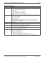
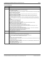
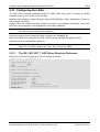
Structure Elements
Element
Description
pfnDrvInit
Pointer to the driver initialization function
(called during initialization process).
eTyp
Driver Type.
Defines the type of peripheral driver is responsible for
(e.g. RX_PERIPHERAL_TYPE_GPIO defines a GPIO driver).
pvPer
Pointer to the driver configuration data.
uNum
Number of elements passed in pvPer
Note:
A List of available drivers can be found in the rcX Driver manual
rcX - Realtime Communication System for netX | Configuration of rcX
DOC050601OS08EN | Revision 8 | English | 2013-06 | Released | Public
© Hilscher, 2005-2013
System Configuration Data Structure
16/94
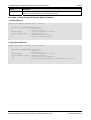
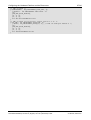
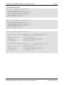
Example:
1. Empty Drivers List
STATIC CONST RX_DRIVER_PERIPHERAL_CONFIG_T atrXDrvCfgPost[] =
{
{NULL, 0, NULL, 0}
};
2. Full featured Drivers List
STATIC CONST RX_DRIVER_PERIPHERAL_CONFIG_T atrXDrvCfgPost[] =
{
{DrvVolInit, RX_PERIPHERAL_TYPE_VOLUME,
atrXVol,
MAX_CNT(atrXVol)},
{DrvXcInit,
RX_PERIPHERAL_TYPE_XC,
atrXXc,
MAX_CNT(atrXXc)},
{DrvGpioInit, RX_PERIPHERAL_TYPE_GPIO,
atrXGpio, MAX_CNT(atrXGpio)},
{DrvHifInit, RX_PERIPHERAL_TYPE_HOST,
atrXHif,
MAX_CNT(atrXHif)},
{DrvPioInit, RX_PERIPHERAL_TYPE_PIO,
atrXPio,
MAX_CNT(atrXPio)},
{DrvPFlsInit, RX_PERIPHERAL_TYPE_PARFLASH, atrXPFlsh, MAX_CNT(atrXPFlsh)},
{DrvSpiInit, RX_PERIPHERAL_TYPE_SPI,
atrXSpi,
MAX_CNT(atrXSpi)},
{DrvSFlsInit, RX_PERIPHERAL_TYPE_SERFLASH, atrXSFlsh, MAX_CNT(atrXSFlsh)},
};
rcX - Realtime Communication System for netX | Configuration of rcX
DOC050601OS08EN | Revision 8 | English | 2013-06 | Released | Public
© Hilscher, 2005-2013
System Configuration Data Structure
3.2
17/94
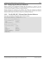
Loading Middleware Modules using tMiddleware
Middleware modules are OS system functions like database support, file system and so on and
must be also defined and loaded like system drivers.
The tMiddleware is used to define all additional modules which should be loaded during the startup
phase of the OS.
Each module is defined by a RX_MIDDLEWARE_CONFIG_T element where the elements are
stored in the atrXMidCfgPost[] array.
tMiddleware holds a pointer to the first element of the middleware module list.
3.2.1
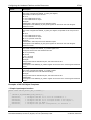
The RX_MIDDLEWARE_CONFIG_T Structure Reference
typedef struct RX_MIDDLEWARE_CONFIG_Ttag
{
RX_FATAL (* pfnMidInit) (void* pvPar,UINT uPar);
void*
pvPar;
UINT
uPar;
} RX_MIDDLEWARE_CONFIG_T;
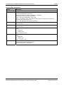
Structure Elements
Element
Description
pfnMidInit
Pointer to the module initialization function (called during the initialization process).
pvPer
Pointer to the module configuration data.
uPar
Number of elements passed in pvPer
Note:
A List of available middleware modules can be found in the rcX Middleware manual
Example:
1. Empty Middleware Modules List
STATIC CONST RX_MIDDLEWARE_CONFIG_T atrXMidCfgPost [] = {
{NULL,NULL,0}
};
2. Full featured Middleware Modules List
STATIC CONST RX_MIDDLEWARE_CONFIG_T atrXMidCfgPost[] = {
{MidDatabaseInit,NULL,0},
{MidSysInit,NULL,0},
{MidFatInit,NULL,0}
};
rcX - Realtime Communication System for netX | Configuration of rcX
DOC050601OS08EN | Revision 8 | English | 2013-06 | Released | Public
© Hilscher, 2005-2013
Defining the Application-Tasks
4
18/94
Defining the Application-Tasks
Each application task, which should be loaded be the rcX, must be defined in the
atrXStaticTasks[ ] array.
A task is defined by the task name, a pointer to the task stack, the task entry function and an
optional task leave function.
A task record follows the structure reference RX_STATIC_TASK_T, defined in the header file
"rX_Config.h".
4.1
The RX_STATIC_TASK_T Structure Reference
typedef struct RX_STATIC_TASK_Ttag {
STRING
szTskNam[16];
UINT32
ulPrio;
UINT32
ulTok;
UINT32
ulInst;
void*
pvStck;
UINT32
ulStckSiz;
UINT32
ulThrhld;
UINT32
ulSrtMod;
void
(* fnTask) (void* pvInpt);
void
(* fnTskLve) (void);
UINT32
ulInp;
UINT32
aulRes[8];
} RX_STATIC_TASK_T;
Each configured task must have a different (unique) task priority “ulPrio” and token “ulTok”.
The initial priority value can be changed during runtime.
However, if it is changed during runtime, it is still not allowed to have the same priority value active
in more than one task at the same time, which is a restriction of the rcX scheduler.
The token (ulTok) is a unique and non-changeable value used to identify the task within the
system.
The same task name can be used multiple times (szTskNam[ ]). But than the instance number has
to differ for each instantiated task.
Generally, the instance number ulInst starts with value 0 and is incremented for each
additional created task instance.
During runtime, a task is able to determine its own instance number.
rcX - Realtime Communication System for netX | Configuration of rcX
DOC050601OS08EN | Revision 8 | English | 2013-06 | Released | Public
© Hilscher, 2005-2013
Defining the Application-Tasks
19/94
Structure Elements
Element
Description
szTskNam[16]
Task name as a NUL terminated ASCII string with a maximum length of 16 Bytes (including the
terminating NUL character).
ulPrio
Task Priority (changeable during runtime).
Valid values:
TSK_PRIO_1 to TSK_PRIO_55, defined in "rX_Priorities.h".
TSK_PRIO_1 = highest priority
ulTok
Task Token.
Unique task identification number. Invalid or double defined values will result in an
unrecoverable kernel fault.
Valid values:
TSK_TOK_1 to TSK_TOK_55, defined in "rX_Tokens.h"
ulInst
Task Instance Number.
Used to distinguish between multiple instances of the same task.
Starts with the value 0 and must be incremented with each new
instance.
pvStck
Stack Pointer.
Set to NULL forces the rcX to allocate memory for the stack.
If the pointer is defined, it must be set to end address of the stack (lowest valid stack address).
The rcX will generate an own, stack pointer, using the stack size and the given stack end
address.
ulStckSiz
Size of the Task Stack
The size must be given in multiples of CPU specific stack elements which is 4 Bytes on the
netX.
rcX needs the stack size to calculate the top of the stack.
The specified element number should never be less than 128.
uThrHld
Not implemented
ulSrtMod
Task Start Mode.
RX_TASK_AUTO_START - task will be created and started by the operating system.
RX_TASK_AUTO_STOP - task will be created in suspended state and must be activated by a
call to rX_SysResumeTask().
fnTsk
Pointer to the Task Entry Function.
Called by the rcX to started the task.
fnTskLve
Task Leave Function.
This function is called whenever a task will shutdown (e.g. at system reset or task deletion).
(Set to NULL. if not used)
ulInp
User Data Pointer
Passed to the task entry function.
aulRes[8]
Reserved.
This area is for future extensions.
rcX - Realtime Communication System for netX | Configuration of rcX
DOC050601OS08EN | Revision 8 | English | 2013-06 | Released | Public
© Hilscher, 2005-2013
Defining the Application-Tasks
20/94
Examples for Application Task Object Templates
1. A Single Task
/* Task Prototype and Definitions */
#define TSK1_STACK_SIZE 256
/* Stack Size in multiples of UINTs */
STATIC UINT auTskStackTest1[TSK1_STACK_SIZE]; /* Task1-Stack */
void FAR fnTskTest1(void FAR*);
void FAR fnTskLeaveTest1(void);
/* Task Main Function */
/* Task Leave Function */
/* Configuration Table of Application Tasks */
STATIC CONST RX_STATIC_TASK_T atrXStaticTasks[] =
{
{
"TESTTSK1",
/* Set Identification */
TSK_PRIO_0, TSK_TOK_1,
/* Set Priority to highest,and unique Token ID */
0,
/* Set Instance to 0 */
&auTskStackTest1[0],
/* Pointer to Stack */
TSK1_STACK_SIZE,
/* Size of Task Stack */
0,
/* Threshold to maximum possible value */
RX_TASK_AUTO_START,
/* Start task automatically */
fnTskTest1,
/* Task function to schedule */
fnTskLeaveTest1,
/* Function called whenever Task is deleted */
0x00000001,
/* Startup Parameter */
{0,0,0,0,0,0,0,0}
/* Reserved Region */
}
};
rcX - Realtime Communication System for netX | Configuration of rcX
DOC050601OS08EN | Revision 8 | English | 2013-06 | Released | Public
© Hilscher, 2005-2013
Defining the Application-Tasks
21/94
2. A Single Task, Configured to be Started Twice
/* Task Prototypes and Definitions */
#define TSK1_STACK_SIZE 256
/* Stack Size in multiples of UINTs */
STATIC UINT auTskStackTest1[TSK1_STACK_SIZE]; /* Task1-Stack */
#define TSK2_STACK_SIZE 256
/* Stack Size in multiples of UINTs */
STATIC UINT auTskStackTest2[TSK2_STACK_SIZE]; /* Task2-Stack */
void FAR fnTskTest(void FAR*);
void FAR fnTskLeaveTest(void);
/* The same Main Function for both */
/* The same Leave Function for both*/
STATIC CONST RX_STATIC_TASK_T atrXStaticTasks[] =
{
{
"TESTTSK",
/* Set Identification */
TSK_PRIO_1, TSK_TOK_1,
/* Set Priority to highestand unique Token ID */
0,
/* Set Instance to 0 */
&auTskStackTest1[0],
/* Pointer to Stack */
TSK1_STACK_SIZE,
/* Size of Task Stack */
0,
/* Threshold to maximum possible value */
RX_TASK_AUTO_START,
/* Start task automatically */
fnTskTest,
/* Task function to schedule */
fnTskLeaveTest,
/* Function called whenever Task is deleted */
0x00000001,
/* Startup Parameter */
{0,0,0,0,0,0,0,0}
/* Reserved Region */
},
{
"TESTTSK",
/* Set Identification */
TSK_PRIO_2, TSK_TOK_2,
/* Set Priority to next highest and Token ID */
1,
/* Set Instance to 1 */
&auTskStackTest2[0],
/* Pointer to Stack */
TSK2_STACK_SIZE,
/* Size of Task Stack */
0,
/* Threshold to maximum possible value */
RX_TASK_AUTO_START,
/* Start task automatically */
fnTskTest,
/* Task function to schedule */
fnTskLeaveTest,
/* Function called whenever Task is deleted */
0x00000001,
/* Startup Parameter */
{0,0,0,0,0,0,0,0}
/* Reserved Region */
}
};
rcX - Realtime Communication System for netX | Configuration of rcX
DOC050601OS08EN | Revision 8 | English | 2013-06 | Released | Public
© Hilscher, 2005-2013
Configuring the Hardware Platform and the Resources
5
5.1
Configuring
Resources
the
Hardware
22/94
Platform
and
the
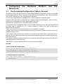
The Peripheral Configuration Table in General
The real-time communication-system for netX utilizes predefined configuration tables for the target
platform peripherals like Timer, Interrupt sources, GPIOs (general purpose I/Os), PIOs (peripheral
I/Os), UART, Ethernet PHY, SPI, FLASH and the watchdog.
For each type of peripheral the "Config.c" file includes a separate configuration table.
Hardware timer and interrupt peripheral are configured using the atrXCfgPre[ ] table. All other
peripheral are configured in the table named atrXDrvCfgPost[].
Both tables are used by the rX_SysEnterKernelExt() function.
It is permitted that a configuration table consist multiple instances, if more than one peripheral of
the same type is available (e.g. if a system contains 4 UARTs, the UART configuration
table will have 4 elements).
There is no limitation on how many resources may be defined in one table.
However, the rcX kernel and the associated drivers can only handle as many resources as the real
hardware platform offers.
If the compiler requires at least one element in an array, the user has to place a particular End-OfList entry into the table. In any other case, the element is optional and can be used to signal a stop
of the table parsing.
This allows to stop the parsing process before the real table end and skips the elements which are
defined behind the End-Of-List entry.
“ENDOFLIST” is the pre-defined ASCII string for the End-Of-List entry.
Example:
1. Basic Peripheral Configuration
STATIC CONST FAR RX_PERIPHERAL_CONFIG_T atrXCfgPre[] =
{
{RX_PERIPHERAL_TYPE_TIMER,atrXHwTim,MAX_CNT(atrXHwTim)},
{RX_PERIPHERAL_TYPE_INTERRUPT,atrXInt,MAX_CNT(atrXInt)},
};
2. Empty Peripheral Configuration
STATIC CONST FAR RX_EXAMPLE_T atrXPeripheralCfg[] =
{
{{"ENDOFLIST"}}
};
rcX - Realtime Communication System for netX | Configuration of rcX
DOC050601OS08EN | Revision 8 | English | 2013-06 | Released | Public
© Hilscher, 2005-2013
Configuring the Hardware Platform and the Resources
5.2
23/94
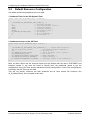
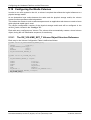
Default Resource Configuration
rcX needs at least two peripherals to be run-able.
1. Hardware Timer for the OS-System-Timer
STATIC CONST FAR RX_HWTIMER_SET_T atrXHwTim[] =
{
{
{"SYSTIMER",RX_PERIPHERAL_TYPE_TIMER,0}, */
0,
/* use GPIO_counter0 */
1000,
/* 1000 microseconds = 1msec */
TRUE,
/* Continuous Mode */
TRUE,
/* Interrupt enabled */
FALSE,
/* No external Clock */
RX_HWTIMER_TRIGGER_NONE,
/* No Trigger */
0,
/* No I/O reference */
0
/* No Prescaler */
}
};
2. Hardware Interrupt of the OS-Timer
STATIC CONST FAR RX_INTERRUPT_SET_T atrXInt[] =
{
{
{"SYSTIMER",RX_PERIPHERAL_TYPE_INTERRUPT,0}, /* System Timer interrupt */
SRT_vic_irq_status_timer0,
/* Use external Timer0 Interrupt */
29,
/* Priority 29 */
RX_INTERRUPT_MODE_SYSTEM,
/* Allow interrupt to be a thread */
RX_INTERRUPT_EOI_AUTO,
/* EOI by RX */
RX_INTERRUPT_TRIGGER_RISING_EDGE, /* Edge triggered */
RX_INTERRUPT_PRIORITY_STANDARD,
/* Normal Priority */
RX_INTERRUPT_REENTRANCY_DISABLED, /* Interrupt itself is not reentrant */
},
};
Both, the timer object and the interrupt object must be defined with the name “SYSTIMER” and
instance number 0. rcX uses the name to identify both, the peripheral record to get the
configuration of the OS-Timer and the hardware interrupt configuration. If one of the configurations
is missing, the OS-Timer will not work.
This will not directly influence the task scheduler but all timer based OS functions, like
rX_SysSleepTask(), are not usable in this case.
rcX - Realtime Communication System for netX | Configuration of rcX
DOC050601OS08EN | Revision 8 | English | 2013-06 | Released | Public
© Hilscher, 2005-2013
Configuring the Hardware Platform and the Resources
5.3
24/94
Defining the Hardware in Peripheral Objects
Each peripheral table, in the "Config.c" file, has a specific structure and specifies at least the
name of the peripheral, its type and the instance number. The identification of a particular
peripheral is done by its name and instance number.
All peripheral drivers are providing a Drv_XxIdentify() function. A user application will use this
function to examine the available objects, created by a driver, if it searches for a specific peripheral
object. Searching is done by passing the object name and instance number and if the object is
available, the function will return a handle to it.
This handle is necessary for later requests to the peripheral.
Drivers and their functions are described in the “Drivers Function Reference Manual".
rcX - Realtime Communication System for netX | Configuration of rcX
DOC050601OS08EN | Revision 8 | English | 2013-06 | Released | Public
© Hilscher, 2005-2013
Configuring the Hardware Platform and the Resources
5.3.1
25/94
The RX_PERIPHERAL_HEADER_T Peripheral Object Header
Structure
Each entry in a peripheral table consists of a preceding structure which provides the name, type
and instance number of the peripheral.
The preceding structure is defined as follows:
typedef struct RX_PERIPHERAL_HEADER_Ttag
{
STRING
szIdn[16];
RX_PERIPHERAL_TYPE eTyp;
UINT
uInst;
} RX_PERIPHERAL_HEADER_T;
Structure Elements
Element
Description
szIdn
Object identification string as a NUL terminated string with a maximum of 16 bytes (including the
NUL character)
eTyp
Peripheral Type.
Only the appropriate types are allowed and must correspond to the configured peripheral.
Following types are defined:
RX_PERIPHERAL_TYPE_TIMER - Hardware Timer
RX_PERIPHERAL_TYPE_INTERRUPT - Hardware Interrupt
RX_PERIPHERAL_TYPE_PIO - Programmable I/O
RX_PERIPHERAL_TYPE_GPIO - General Purpose I/O
RX_PERIPHERAL_TYPE_WATCHDOG - Hardware Watchdog
RX_PERIPHERAL_TYPE_LED - LED
RX_PERIPHERAL_TYPE_UART - UART
RX_PERIPHERAL_TYPE_USB - USB
RX_PERIPHERAL_TYPE_FIFOCHANNEL - FIFO Channel
RX_PERIPHERAL_TYPE_HOST - HOST Interface
RX_PERIPHERAL_TYPE_PARFLASH - Parallel FLASH
RX_PERIPHERAL_TYPE_SERFLASH - Serial FLASH
RX_PERIPHERAL_TYPE_VOLUME - Volume Media
RX_PERIPHERAL_TYPE_RAMDISK - RAM Disk
RX_PERIPHERAL_TYPE_XC - Extension Controller
RX_PERIPHERAL_TYPE_PHY - Ethernet Phy
RX_PERIPHERAL_TYPE_EDD - Ethernet Device
RX_PERIPHERAL_TYPE_TRACE - Diagnosis Trace
uInst
Instance Number.
Used if a peripheral exist several times (e.g. UART) and necessary to distinguish between them.
The instance number must be different for each one using the same name.
0 = first instance
rcX - Realtime Communication System for netX | Configuration of rcX
DOC050601OS08EN | Revision 8 | English | 2013-06 | Released | Public
© Hilscher, 2005-2013
Configuring the Hardware Platform and the Resources
26/94
Example:
Interrupt:
{
{"SYSTIMER",RX_PERIPHERAL_TYPE_INTERRUPT,0}, /* System Timer interrupt */
…
}
Timer:
{
{"MYTIMER",RX_PERIPHERAL_TYPE_TIMER,0}, /* My Timer #0*/
…
}
{
{"MYTIMER",RX_PERIPHERAL_TYPE_TIMER,1}, /* My Timer #1*/
…
}
UART:
{
{"URT_NVR",RX_PERIPHERAL_TYPE_UART,0}, /* 3964R serial Port #0 */
…
}
rcX - Realtime Communication System for netX | Configuration of rcX
DOC050601OS08EN | Revision 8 | English | 2013-06 | Released | Public
© Hilscher, 2005-2013
Configuring the Hardware Platform and the Resources
5.4
27/94
Configuring the Trace Memory Pool
The rcX kernel includes a trace buffer management. At least one trace buffer has to be
defined, in order to record the reported traces of an application task.
The size of the trace buffer defines the number entries which can be stored. Each trace entry has a
size of 48 bytes. Dividing the total buffer size through the entry size will deliver the amount of
elements which can be stored without getting a buffer overrun.
Trace entries are stored into a FIFO (first in - first out) handled buffer. Once the buffer is
completely filled, no further entries are possible and new trace data will never overwrite the already
stored entries.
Each traced element that is read by an application unloads the buffer by one entry.
For each trace record, you may specify an enhanced application specific parameter field of any
size. The memory, which is needed to store those extended parameter fields, is not taken from the
trace buffer memory. It will be allocated from the dynamic memory pool. If the dynamic memory
has reached a definable limit, further trace entries are recorded without the specified extended
parameter field.
Configuration of the trace memory takes place in the atrXTrc[ ] table.
Each entry configures one trace memory buffer, accessible from an application task via
kernel functions.
The kernel will create the trace memory objects during the rcX initialization process in
rX_SysEnterKernelExt().
Location where to locate the trace memory
Size of the trace memory
Minimum limit of dynamic memory
rcX - Realtime Communication System for netX | Configuration of rcX
DOC050601OS08EN | Revision 8 | English | 2013-06 | Released | Public
© Hilscher, 2005-2013
Configuring the Hardware Platform and the Resources
5.4.1
The RX_TRACE_SET_T
Reference
Trace
28/94
Memory
Object
Structure
Each entry in the Trace Memory Configuration Table is defined as follows:
typedef struct RX_TRACE_SET_Ttag
{
RX_PERIPHERAL_HEADER_T tCfgHd;
UINT8*
UINT32
UINT32
} RX_TRACE_SET_T;
pbSrt;
ulSiz;
ulLmt;
Structure Elements
Element
Description
tCfgHd
Peripheral header information structure
pbSrt
Start Address.
Start address of a memory area that will be added to the global trace memory pool.
It will be used in conjunction with the functions rX_FltLoggFault() and rX_FltGetOldestFault() in
order to trace a record or to read a record.
ulSiz
Size.
Size of the memory area in bytes (must be a multiple of 48 Bytes per entry).
ulLmt
Allocation Limit
The dynamic memory allocation limit defines the amount of memory to be left free.
Used if extended parameter fields are defined for the trace entries.
Examples of Trace Memory Object Templates
1. Definition of a Single Trace Memory Pool
- using a global memory buffer
/* Trace Memory Pool defined as an array of bytes */
#define RX_TRACE_MEMORY_SIZE 1024
UINT8 abTrcMem[RX_TRACE_MEMORY_SIZE];
STATIC CONST FAR RX_TRACE_SET_T atrXTrc[] =
{
{
{"TRACEBUFFER",RX_PERIPHERAL_TYPE_TRACE,0},
(UINT8 FAR*)abTrcMem, sizeof(abTrcMem),
sizeof(RX_STATIC_MEMORY_SIZE)/2 /* half dynamic memory shall be left */
}
};
2. Definition of Multiple Trace Memory Pools
- using discrete address pointers
STATIC CONST FAR RX_TRACE_SET_T atrXTrc[] =
{
{
{"TRC_SDRAM",RX_PERIPHERAL_TYPE_TRACE,0},
(UINT8 FAR*)0x80000000,0x100000,/* Configure the SDRAM pool */
0x100000
}
{
{"TRC_SRAM",RX_PERIPHERAL_TYPE_TRACE,0},
(UINT8 FAR*)0xC8000000,0x100000, /* Configure the SRAM pool */
0x100000
}
};
rcX - Realtime Communication System for netX | Configuration of rcX
DOC050601OS08EN | Revision 8 | English | 2013-06 | Released | Public
© Hilscher, 2005-2013
Configuring the Hardware Platform and the Resources
5.5
29/94
Configuring the Hardware Interrupts
A real-time system is living on events reported by hardware interrupts.
Using interrupts has the advantage that a task can wait on a special event without
consuming CPU processing cycles.
This allows other processes to run until the event occurs. To realize an ideal and fast real-time
system reaction, all processes should forcibly wait on events, consuming a minimum of the CPU’s
processing cycles.
Interrupt configuration for the rcX takes place in atrXInt[ ] table, located in "Config.c" file.
Each table entry configures one hardware interrupt. The corresponding driver will create the
hardware interrupt objects during the rcX initialization.
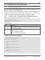
5.5.1
The RX_INTERRUPT_SET_T
Reference
Interrupt
Object
Structure
Each entry in the hardware Interrupt configuration table is defined as follows:
typedef struct RX_INTERRUPT_SET_Ttag
{
RX_PERIPHERAL_HEADER_T
tCfgHd;
UINT
UINT
RX_INTERRUPT_MODE
RX_INTERRUPT_EOI
RX_INTERRUPT_TRIGGER
RX_INTERRUPT_PRIORITY
RX_INTERRUPT_REENTRANCY
RX_TASK_PRIORITY
RX_TASK_TOKEN
UINT
} RX_INTERRUPT_SET_T;
uIntNum;
uPrio;
eMod;
eEoi;
eTrig;
ePrio;
eRntr;
eTaskModePriority;
eTaskToken;
uTaskStackSize;
rcX - Realtime Communication System for netX | Configuration of rcX
DOC050601OS08EN | Revision 8 | English | 2013-06 | Released | Public
© Hilscher, 2005-2013
Configuring the Hardware Platform and the Resources
30/94
Structure Elements
Element
Description
tCfgHd
Peripheral header information structure
uIntNum
Interrupt Number.
Defines the physical interrupt number within the target interrupt
controller.
The interrupt controller reference manual of the target platform should inform about the relation
between interrupt numbers and real interrupt sources.
uPrio
Interrupt Priority.
Defines the interrupt priority. This can be either vectored or non-vectored, depending of the
interrupt number.
0 - 15 = non-vectored interrupt
16 - 31 = vectored interrupt
31 = highest priority
eMod
Interrupt Mode.
Defines how the application interrupt service routine is treated when it is called by the interrupt
handler.
One of the 3 modes are possible:
RX_INTERRUPT_MODE_INTERRUPT
- The application interrupt service routine (ISR) is not interruptible and interrupts are globally
disabled if it is called.
- Not all rcX kernel functions are allowed within the ISR.
- End of Interrupt (EOI) is issued by the driver, after returning from the ISR (ISR should NOT
issue the EOI)
- eEoi idefinition is NOT used.
RX_INTERRUPT_MODE_SYSTEM
- The application interrupt service routine (ISR) is called and
interrupts are globally disabled.
- Non-blocking rcX kernel functions are allowed.
- If interrupt nesting is desired, the ISR has to handle the enable and disable interrupt.
- Protection of shared data against concurrent access may be
necessary.
- EOI handling is defined by eEoi
RX_INTERRUPT_MODE_TASK
- The application interrupt service routine (ISR) will be handled in a task, automatically created
by the rcX.
- Interrupt source is disabled while the ISR is active.
- The ISR is interruptible by any task with a higher priority
- ISR priority is defined by ePrio
- Any rcX function can be used.
- EOI is handled by the rcX driver
eEoi
EOI (End of Interrupt) Handling.
Only used when eMod = RX_INTERRUPT_MODE_SYSTEM.
Possible settings:
RX_INTERRUPT_EOI_AUTO
The end of interrupt (EOI) signal to the interrupt controller is
automatically issued by the rcX interrupt driver, after returning from the application ISR.
RX_INTERRUPT_EOI_SELF
- The end of interrupt (EOI) signal must be handled by the
application ISR using the function Drv_IntEndOfInterrupt().
- Interrupts are globally disabled and enabled when leaving the ISR.
- Interrupts can be enabled by the ISR if necessary, but must than be disabled before leaving it.
eTrig
Trigger Type of the Interrupt Source.
Possible settings:
RX_INTERRUPT_TRIGGER_RISING_EDGE - The interrupt is rising edge triggered.
RX_INTERRUPT_TRIGGER_FALLING_EDGE - The interrupt is falling edge triggered.
RX_INTERRUPT_TRIGGER_LEVEL_NULL - The interrupt is level triggered, active low.
RX_INTERRUPT_TRIGGER_LEVEL_ONE - The interrupt is level triggered, active high.
rcX - Realtime Communication System for netX | Configuration of rcX
DOC050601OS08EN | Revision 8 | English | 2013-06 | Released | Public
© Hilscher, 2005-2013
Configuring the Hardware Platform and the Resources
31/94
Element
Description
ePrio
Interrupt Priority.
ePrio can be used to define the basic priority of the interrupt.
Possible settings:
RX_INTERRUPT_PRIORITY_STANDARD - Interrupt are handled by the interrupt controller
using the standard priority according to the specified priority uPrio.
RX_INTERRUPT_PRIORITY_HIGH - Not implemented.
eRntr
Not implemented on rcX V2.
eTaskModePriority
ISR Task Priority.
Only used if eMod = RX_INTERRUPT_MODE_TASK is defined
Possible settings:
TSK_PRIO_1 to TSK_PRIO_55, (defined in "rX_Priorities.h").
TSK_PRIO_1 = highest priority
eTaskToken
ISR Task Token.
Only used if eMod = RX_INTERRUPT_MODE_TASK is defined
Possible settings:
TSK_TOK_1 to TSK_TOK_55, (defined in "rX_Tokens.h").
uTaskStackSize
ISR Task Stack Size.
Only used if eMod = RX_INTERRUPT_MODE_TASK is defined
The size must be given in multiples of CPU specific stack elements which is 4 Bytes on the
netX.
rcX needs the stack size to calculate the top of the stack.
The specified element number should never be less than 128.
Examples of Hardware Interrupt Object Templates
1. Defining a Single Interrupt - using RCX_INTERRUPT_MODE_TASK
STATIC CONST FAR RX_INTERRUPT_SET_T atrXInt[] =
{
{
{"MYTIMER",RX_PERIPHERAL_TYPE_INTERRUPT,0},
19,
/* Use Timer 2 Interrupt =
Physical Interrupt No.19 */
3,
/* Priority 3 */
RX_INTERRUPT_MODE_TASK,
/* Allow interrupt to be treated as task */
RX_INTERRUPT_EOI_AUTO,
/* EOI by ISR and IRQs enabled */
RX_INTERRUPT_TRIGGER_RISING_EDGE, /* Rising edge triggered */
RX_INTERRUPT_PRIORITY_STANDARD,
/* Normal Priority in the system */
RX_INTERRUPT_REENTRANCY_ENABLED, /* Interrupt itself is reentrant */
TSK_PRIO_5,
TSK_TOK_5,
1024
},
}
rcX - Realtime Communication System for netX | Configuration of rcX
DOC050601OS08EN | Revision 8 | English | 2013-06 | Released | Public
© Hilscher, 2005-2013
Configuring the Hardware Platform and the Resources
32/94
2. Single Interrupt - using RX_INTERRUPT_MODE_SYSTEM
STATIC CONST FAR RX_INTERRUPT_SET_T atrXInt[] =
{
{
{"SYSTIMER",RX_PERIPHERAL_TYPE_INTERRUPT,0},
19,
/* Use Timer 2 Interrupt =
Physical Interrupt No.19 */
3,
/* Priority 3 */
RX_INTERRUPT_MODE_SYSTEM,
/* Allow interrupt to be treated as task */
RX_INTERRUPT_EOI_AUTO,
/* EOI by ISR and IRQs enabled */
RX_INTERRUPT_TRIGGER_RISING_EDGE, /* Rising edge triggered */
RX_INTERRUPT_PRIORITY_STANDARD,
/* Normal Priority in the system */
RX_INTERRUPT_REENTRANCY_ENABLED, /* Interrupt itself is reentrant */
},
}
3.) Defining Multiple Interrupts
STATIC CONST FAR RX_INTERRUPT_SET_T atrXInt[] =
{
{
{"VERBOSE",RX_PERIPHERAL_TYPE_INTERRUPT,0},
1,
/* Use external UART0 Interrupt =
Physical Interrupt No.1 */
17,
/* Priority 17 */
RX_INTERRUPT_MODE_INTERRUPT,
/* Allow interrupt not to be nested */
RX_INTERRUPT_EOI_AUTO,
/* EOI automatically by RX */
RX_INTERRUPT_TRIGGER_RISING_EDGE, /* Rising edge triggered */
RX_INTERRUPT_PRIORITY_STANDARD,
/* Normal Priority */
RX_INTERRUPT_REENTRANCY_DISABLED, /* Interrupt itself is not reentrant */
},
{
{"SYSTIMER",RX_PERIPHERAL_TYPE_INTERRUPT,0},
19,
/* Use Timer 2 Interrupt =
Physical Interrupt No.19 */
3,
/* Priority 3 */
RX_INTERRUPT_MODE_TASK,
/* Allow interrupt to be treated as task */
RX_INTERRUPT_EOI_AUTO,
/* EOI by ISR and IRQs enabled */
RX_INTERRUPT_TRIGGER_RISING_EDGE, /* Rising edge triggered */
RX_INTERRUPT_PRIORITY_STANDARD,
/* Normal Priority in the system */
RX_INTERRUPT_REENTRANCY_DISABLED,
TSK_PRIO_20,
TSK_TOK_20,
1024
},
}
rcX - Realtime Communication System for netX | Configuration of rcX
DOC050601OS08EN | Revision 8 | English | 2013-06 | Released | Public
© Hilscher, 2005-2013
Configuring the Hardware Platform and the Resources
5.6
33/94
Configuring Hardware Timers and Counters
Hardware timers allow the handling of cyclic functions and also providing an interrupt which must
be configured. The features of the hardware timers depend on the underlying hardware platform.
NetX timers are providing a common feature set including reload-capabilities.
Configuration of the
the "Config.c" file.
hardware
timer
takes
place
the
atrXTim[
]
table,
located
in
Each table entry configures one hardware timer and the corresponding hardware driver will
create a timer object for each defined timer.
rcX - Realtime Communication System for netX | Configuration of rcX
DOC050601OS08EN | Revision 8 | English | 2013-06 | Released | Public
© Hilscher, 2005-2013
Configuring the Hardware Platform and the Resources
5.6.1
34/94
The RX_HWTIMER_SET_T Hardware Timer/Counter Object
Structure Reference
Each entry in the Hardware Timer Configuration Table is defined as follows:
typedef struct RX_HWTIMER_SET_Ttag
{
RX_PERIPHERAL_HEADER_T tCfgHd;
UINT
UINT
BOOLEAN
BOOLEAN
BOOLEAN
RX_HWTIMER_TRIGGER
UINT
UINT
} RX_HWTIMER_SET_T;
uTimNum;
uMax;
fCont;
fInt;
fExt;
eTrig;
uExtIoRef;
uPscl;
Structure Elements
Element
Description
tCfgHd
Peripheral header information structure
uTimNum
Physical Timer/Counter number.
Possible values:
0 - 4 = number of the GPIO timer
uMax
Timer / Counter Value.
One-Shot / Reload Timer:
fExt = FALSE (use internal clock source)
uMax defines the time in microseconds until the timer is reloaded
(in cyclic mode) or stopped (in one-shot mode).
One-Shot / Reload Timer:
fExt = TRUE (external source trigger mode).
uMax defines the absolute count number until counter is reloaded
(in cyclic mode) or stopped (in one-shot mode).
fCont
Continue Flag.
This flag decides if the timer / counter is handled as one-shot or
cyclic timer / counter.
TRUE = set the timer / counter into cyclic mode.
FALSE = set the timer / counter into one-shot mode.
fInt
Enable Interrupt,
This flag configures if the timer / counter generates an interrupt
whenever the value, given in uMax, is reached
TRUE = enable interrupt
FALSE = disable interrupt
fExt
External Clock Source.
fExt defines if an external clock source is used.
TRUE = external clock source used
FALSE = internal clock source used
eTrig
Trigger Type.
Possible Settinge:
RX_HWTIMER_TRIGGER_NONE - The counter is not configured in external trigger mode.
RX_HWTIMER_TRIGGER_RISING_EDGE - The timer / counter is rising edge triggered.
RX_HWTIMER_TRIGGER_FALLING_EDGE - The timer / counter is falling edge triggered.
RX_HWTIMER_TRIGGER_LEVEL_NULL - The timer / counter is low level triggered.
RX_HWTIMER_TRIGGER_LEVEL_ONE - The timer / counter is high level triggered.
uExtIoRef
External Clock Source.
This value defines the PIO / GPIO number used as the clock source.
uExtIoRef = PIO / GPIO input pin number.
rcX - Realtime Communication System for netX | Configuration of rcX
DOC050601OS08EN | Revision 8 | English | 2013-06 | Released | Public
© Hilscher, 2005-2013
Configuring the Hardware Platform and the Resources
Element
Description
uPscl
Timer unit prescaler value.
Not supported on netX
35/94
Examples of Hardware Interrupt Object Templates
1.) A Single Hardware Timer
STATIC CONST FAR RX_HWTIMER_SET_T atrXHwTim[] =
{
{
{"SYSTIMER",RX_PERIPHERAL_TYPE_TIMER,0},
0, /* use GPIO_counter0 */
1000, /* 1000 microseconds = 1msec */
TRUE, /* Continuous Mode */
TRUE, /* Interrupt enabled */
FALSE, /* No external clock as input trigger, use internal clock */
RX_HWTIMER_TRIGGER_NONE, /* No external Trigger */
0, /* No I/O reference */
0 /* No Prescaler */
}
}
2.) Multiple Hardware Timers
STATIC CONST FAR RX_HWTIMER_SET_T atrXHwTim[] =
{
{
{"MYCOUNTER",RX_PERIPHERAL_TYPE_TIMER,0},
1, /* use counter 1 */
100, /* 100 clocks */
TRUE, /* Continuous Mode, trigger again and again */
TRUE, /* Interrupt enabled */
TRUE /* Use external Trigger */
RX_HWTIMER_RISING_EDGE, /* Trigger at each rising edge impulse */
5, /* External I/O input-pin reference No.5 */
0
/* Prescaler disable */
},
{
{"DAYTICK",RX_PERIPHERAL_TYPE_TIMER,0},
0,
86400000, /* Clock Every day = 24*60*60*1000 microseconds */
TRUE, /* Continuous Mode */
TRUE, /* Interrupt enabled */
FALSE, /* No external Clock */
RX_HWTIMER_TRIGGER_NONE, /* No Trigger */
0, /* No I/O reference */
128
/* Prescaler enabled to support low-resolution timer */
}
}
rcX - Realtime Communication System for netX | Configuration of rcX
DOC050601OS08EN | Revision 8 | English | 2013-06 | Released | Public
© Hilscher, 2005-2013
Configuring the Hardware Platform and the Resources
5.7
36/94
Configuring the UARTs
The netX offers up to three “UART” units. These units provide the physical layer of the RS-232
interface. In addition to the basic functions, the units also providing interrupt handling as well as a
character FIFOs.
UARTs are configurable via the atrXUrt[ ] in the "Config.c" file. Each table entry configures one
UART. The UART driver will create an own UART object for each entry, during the rcX initialization
sequence.
The UART configuration provides all necessary information for the UART driver to handle the
UARTs and contains at least the physical port number, the baud-rate and transmission
properties.
rcX - Realtime Communication System for netX | Configuration of rcX
DOC050601OS08EN | Revision 8 | English | 2013-06 | Released | Public
© Hilscher, 2005-2013
Configuring the Hardware Platform and the Resources
5.7.1
37/94
The RX_UART_SET_T UART Object Structure Reference
Each entry in the UART configuration table is defined as follows:
typedef struct RX_UART_SET_Ttag
{
RX_PERIPHERAL_HEADER_T tCfgHd;
UINT
RX_UART_BAUDRATE
RX_UART_PARITY
RX_UART_STOPBIT
RX_UART_DATABIT
UINT
UINT
RX_UART_RTS
RX_UART_RTS_POLARITY
UINT
UINT
RX_UART_CTS
RX_UART_CTS_POLARITY
} RX_UART_SET_T;
uUrtNum;
eBdRte;
ePrty;
eStp;
eDat;
uRxFifoLvl;
uTxFifoLvl;
eRts;
eRtsPol;
uRtsForrun;
uRtsTrail;
eCts;
eCtsPol;
Structure Elements
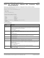
Element
Description
tCfgHd
Peripheral header Information structure
uUrtNum
Physical UART Number.
Possible values:
uUrtNum = 0..2, defines the physical UART number.
eBdRte
UART Baudrate.
Possible settings:
RX_UART_BAUDRATE_300 = 3
300 Baud
RX_UART_BAUDRATE_600 = 6
600 Baud
RX_UART_BAUDRATE_1200 = 12
1,2 kBaud
RX_UART_BAUDRATE_2400 = 24
2,4 kBaud
RX_UART_BAUDRATE_4800 = 48
4,8 kBaud
RX_UART_BAUDRATE_9600 = 96
9,6 kBaud
RX_UART_BAUDRATE_19200 = 192
19,2 kBaud
RX_UART_BAUDRATE_38400 = 384
38,4 kBaud
RX_UART_BAUDRATE_57600 = 576
57,6 kBaud
RX_UART_BAUDRATE_115200 = 1152
115,2 kBaud
It is also possible to configure other baud-rate than the given ones. The new value can be
caculated by the following formular:
eBdRate = baudrate / 100
ePrty
Parity Setting.
Possible settings:
RX_UART_PARITY_NONE - No parity checking
RX_UART_PARITY_ODD - Odd parity
RX_UART_PARITY_EVEN - Even parity
rcX - Realtime Communication System for netX | Configuration of rcX
DOC050601OS08EN | Revision 8 | English | 2013-06 | Released | Public
© Hilscher, 2005-2013
Configuring the Hardware Platform and the Resources
38/94
Element
Description
eStp
Stop-Bit Setting.
Possible settings:
RX_UART_STOPBIT_1 - 1 stop-bit
RX_UART_STOPBIT_2 - 2 stop-bits
eDat
Data Width.
Possible settings:
RX_UART_DATABIT_5 - 5 data Bits
RX_UART_DATABIT_6 - 6 data Bits
RX_UART_DATABIT_7 - 7 data Bits
RX_UART_DATABIT_8 - 8 data Bits
RX_UART_DATABIT_9 - 9 data Bits
uRxFifLvl
Receive FIFO Configuration.
Enables the 16 byte receive FIFO and configures at which amount of characters in the FIFO the
receive buffer full signal is issued.
Possible values:
0 = receive FIFO disabled
1-16 = enabled the 16 Byte receive FIFO and set the receive buffer signaling to the given value.
uTxFifLvl
Transmit FIFO Configuration.
Enables the 16 byte transmit FIFO and also defines the amount of characters under which the
FIFO fill level has to fall before the transmit buffer empty signal is issued.
0 = transmit FIFO disabled
1-16 = enabled the 16 Byte transmit FIFO and sets the amount of character under which the fill
level has to fall before issuing the transmit buffer empty signal.
eRts
RTS Control.
Possible values:
RX_UART_RTS_NONE - RTS not support
RX_UART_RTS_AUTO_INBITS - RTS signal is automatically asserted by the driver and values
uRtsForrun and uRtsTrail are given in number of bits.
RX_UART_RTS_AUTO_INCLOCKS - RTS signal is automatically asserted by the driver and
values uRtsForrun and uRtsTrail are given in system clock cycles.
RX_UART_RTS_SELF - RTS signal is driven by the application itself.
eRtsPol
RTS Signal Polarity.
Possible values:
RX_UART_RTS_DEFAULT - RTS default setting
RX_UART_RTS_ACTIVE_HIGH - RTS signal is active high
RX_UART_RTS_ACTIVE_LOW - RTS signal is active low
uRtsForrun
RTS Forrun.
eRts defines the RTS Signal forerun before the transmit character is sent.
The value can either be configured in multiple of bits
eRts = RX_UART_RTS_AUTO_INBITS
or in system clock cycles
eRts = RX_UART_RTS_AUTO_INCLOCKS.
uRtsTrail
RTS Trail.
In the case that the RTS control is configured to RX_UART_RTS_AUTO_..., this value defines
the RTS signal trail, that is adjusted and kept after the transmission of a character.
The value can either be configured in multiple of bits,
eRts = RX_UART_RTS_AUTO_INBITS
or in system clock cycles
eRts = RX_UART_RTS_AUTO_INCLOCKS.
eCts
CTS Control
Configures the behavior and control of the CTS input signal.
Following values may be configured:
RX_UART_CTS_NONE - No CTS control.
RX_UART_CTS_AUTO - CTS signal is automatically monitored by the Driver when a
character is transmitted.
RX_UART_CTS_SELF - CTS signal is monitored by the application itself.
rcX - Realtime Communication System for netX | Configuration of rcX
DOC050601OS08EN | Revision 8 | English | 2013-06 | Released | Public
© Hilscher, 2005-2013
Configuring the Hardware Platform and the Resources
Element
Description
eCtsPol
CTS Polarity.
Configures the polarity of the CTS input signal.
Following values my be configured:
RX_UART_CTS_DEFAULT - CTS default setting
RX_UART_CTS_ACTIVE_HIGH - CTS signal is active high
RX_UART_CTS_ACTIVE_LOW - CTS signal is active low
rcX - Realtime Communication System for netX | Configuration of rcX
DOC050601OS08EN | Revision 8 | English | 2013-06 | Released | Public
39/94
© Hilscher, 2005-2013
Configuring the Hardware Platform and the Resources
40/94
Examples of UART Object Templates
1. A Single UART
STATIC CONST FAR RX_UART_SET_T atrXUrt[] =
{
{
{"NVR",RX_PERIPHERAL_TYPE_UART,0},
0, /* Use UART 0 */
RX_UART_BAUDRATE_9600, /* Baudrate 9.6Kbaud */
RX_UART_PARITY_EVEN, /* Even Parity */
RX_UART_STOPBIT_1, /* 1 Stop bit */
RX_UART_DATABIT_8, /* 8 Data bits */
0, /* No RX-FIFO */
0, /* No TX-FIFO */
RX_UART_RTS_NONE, /* No RTS in use */
RX_UART_RTS_DEFAULT, /* No RTS in use */
0, /* No RTS forerun */
0, /* No RTS trail */
RX_UART_CTS_NONE, /* No CTS in use */
RX_UART_CTS_ DEFAULT /* No CTS in use */
}
}
2. Multiple UARTs
STATIC CONST FAR RX_UART_SET_T atrXUrt[] =
{
{
{"VERBOSE",RX_PERIPHERAL_TYPE_UART,0}, /* Verbose Port */
0, /* Use UART 0 */
RX_UART_BAUDRATE_38400, /* Baudrate 38,4Kbaud */
RX_UART_PARITY_NONE, /* None Parity */
RX_UART_STOPBIT_1, /* 1 Stop bit */
RX_UART_DATABIT_7, /* 7 Data bits */
0, /* No RX-FIFO */
0, /* No TX-FIFO */
RX_UART_RTS_NONE, /* No RTS in use */
RX_UART_RTS_DEFAULT, /* No RTS in use */
0, /* No RTS forerun */
0, /* No RTS trail */
RX_UART_CTS_NONE, /* No CTS in use */
RX_UART_CTS_DEFAULT /* No CTS in use */
},
{
{"MYUART1”,RX_PERIPHERAL_TYPE_UART,0}, /* 3964R Port */
3, /* Use UART 3 */
10000, /* Baudrate 1Mbaud */
RX_UART_PARITY_EVEN, /* Even Parity */
RX_UART_STOPBIT_1, /* 1 Stop bit */
RX_UART_DATABIT_8, /* 8 Data bits */
3, /* 3 Element deep RX-FIFO */
3, /* 3 Element deep TX-FIFO */
RX_UART_RTS_NONE, /* No RTS in use */
RX_UART_RTS_ DEFAULT, /* No RTS in use */
0, /* No RTS forerun */
0, /* No RTS trail */
RX_UART_CTS_AUTO, /* CTS automatically */
RX_UART_CTS_ ACTIVE_LOW /* CTS active low */
}
}
rcX - Realtime Communication System for netX | Configuration of rcX
DOC050601OS08EN | Revision 8 | English | 2013-06 | Released | Public
© Hilscher, 2005-2013
Configuring the Hardware Platform and the Resources
5.8
41/94
Configuring the SRAM Bus
The netX offers an SRAM Bus which can be used to connect external static RAM,
parallel FLASH devices or similar devices with a parallel interface and fix timing parameters.
The bus interface consists of four different, configurable, chip-select lines, read/write, address and
data-lines and is located on a fixed address inside the netX.
It does not support devices which need a data refresh cycle, to keep the data valid, or ready/busy
signals.
The SRAM bus configuration takes place in the atrXSRAMbus[ ] table, loacted in the
"Config.c" file.
Each table entry configures a particular SRAM bus area defined by a chip select number and
contains at least the bus width and the wait-states settings for it.
Initialization of the SRAM takes place in the rcX initialization sequence.
rcX - Realtime Communication System for netX | Configuration of rcX
DOC050601OS08EN | Revision 8 | English | 2013-06 | Released | Public
© Hilscher, 2005-2013
Configuring the Hardware Platform and the Resources
5.8.1
42/94
The RX_SRAMBUS_SET_T SRAM Bus Configuration Structure
Reference
Each entry in the SRAM Bus Configuration Table is defined as follows:
typedef struct RX_SRAMBUS_SET_Ttag
{
UINT
uChipSelect;
RX_SRAM_DATAWIDTH_TYPE eDataWidth;
UINT
uWaitStates;
UINT
uPreAccessWaitStates;
UINT
uPostAccessWaitStates;
} RX_SRAMBUS_SET_T;
Structure Elements
Element
Description
uChipSelect
SRAM Bus Chip Select Number.
uChipSelect defines the used chip select number
Possible values:
0..3 = number of available chip select signals
eDataWidth
Data Width.
Possible settings:
RX_SRAMBUS_DATAWIDTH_8BIT - 8Bit Data-Width
RX_SRAMBUS_DATAWIDTH_16BIT - 16Bit Data-Width
RX_SRAMBUS_DATAWIDTH_32BIT - 32Bit Data-Width
uWaitStates
Wait States.
Access time in number of host clock cycles
Possible values:
0..63 = number of cycles
uPreAccessWaitStates
Pre Access Wait States.
Setup time (time between chip select and OE/WE signal) in number of host clock
cycles.
Possible values:
0..3 = number of cycles
uPostAccessWaitStates
Post Access Wait States.
Additional wait states after access in number of host clock
cycles.
Possible values:
0..3 = number of cycles
rcX - Realtime Communication System for netX | Configuration of rcX
DOC050601OS08EN | Revision 8 | English | 2013-06 | Released | Public
© Hilscher, 2005-2013
Configuring the Hardware Platform and the Resources
43/94
Examples of SRAM Bus Configuration
1. 32 Bit Bus Data Width
STATIC CONST FAR RX_SRAMBUS_SET_T atrXSRAMbus[] =
{
{
0,
/* SRAM bus chip select number */
RX_SRAMBUS_DATAWIDTH_32BIT,
/* Data width 32 Bit */
3,
/* Wait state cycles */
3,
/* Setup time */
3,
/* Post access time */
},
};
2. 16 Bit Bus Data Width
STATIC CONST FAR RX_SRAM_SET_T atrXSRAMbus[] =
{
{
1,
/* SRAM bus chip select number */
RX_SRAMBUS_DATAWIDTH_16BIT,
/* Data width 16 Bit */
10,
/* Wait states cycles*/
0,
/* Setup time */
0,
/* Post access time */
},
};
rcX - Realtime Communication System for netX | Configuration of rcX
DOC050601OS08EN | Revision 8 | English | 2013-06 | Released | Public
© Hilscher, 2005-2013
Configuring the Hardware Platform and the Resources
5.9
44/94
Configuring Parallel FLASH
A parallel FLASH component is needed if any type of information should be stored to a non-volatile
media.
Information could be firmware, configuration and user files and data. Parallel FLASH memory also
allows the direct code executed, which is a simple and effective way to save dynamic RAM.
Because of the slower access time of FLASH memory (aprox. 70 ns), direct code execution should
only be used for non-time-critical applications.
Because of the programming behavior of FLASH components, which do not allow any other
accesses to them while programming is in progress, a small program, running in memory is always
needed to re-program the FLASH.
The parallel FLASH configuration is done by the atrXPFlsh[ ] table, located in "Config.c".
Necessary information are the FLASH capacity, the sector sizes and the FLASH memory data bus
width.
Each table entry configures one parallel FLASH chip and the FLASH driver will create a parallel
FLASH object for it. This is done during the rcX initialization sequence and activated by the
rX_SysEnterKernelExt() function.
rcX - Realtime Communication System for netX | Configuration of rcX
DOC050601OS08EN | Revision 8 | English | 2013-06 | Released | Public
© Hilscher, 2005-2013
Configuring the Hardware Platform and the Resources
5.9.1
The RX_PARALLELFLASH_SET_T
Structure Reference
45/94
Parallel FLASH Object
Each entry in the Parallel FLASH configuration table is defined as follows:
#define RX_PARALLELFLASH_MAX_SECTORENTRIES 32
typedef struct RX_TRANSLATIONLAYER_CONFIG_Ttag
{
UINT32 ulSrtOffs;
UINT32 ulSiz;
UINT32 ulBlkSiz;
} RX_TRANSLATIONLAYER_CONFIG_T;
typedef struct RX_PARALLELFLASH_SECTORCONFIG_Ttag {
UINT
uNumOfSec;
UINT32
ulSiz;
RX_PARALLELFLASH_PROTECT eProt;
} RX_PARALLELFLASH_SECTORCONFIG_T;
typedef struct RX_PARALLELFLASH_IDENTITY_Ttag {
UINT uVenCod;
/* Vendor specific ID-Code */
UINT uDevCod;
/* Device specific ID-Code */
} RX_PARALLELFLASH_IDENTITY_T;
typedef struct RX_PARALLELFLASH_SET_Ttag {
RX_PERIPHERAL_HEADER_T
tCfgHd;
RX_PARALLELFLASH_WIDTH
RX_PARALLELFLASH_IDENTITY_T
RX_TRANSLATIONLAYER_CONFIG_T
UINT32
RX_RESULT(*
eWidth;
tIdentity;
tTrnsCfg;
ulBaseAddr;
pfnFlashInitialize)
(RX_HANDLE);
UINT
uNumSecEnt;
RX_PARALLELFLASH_SECTORCONFIG_T
atSecCfgTbl[RX_PARALLELFLASH_MAX_SECTORENTRIES];
} RX_PARALLELFLASH_SET_T;
rcX - Realtime Communication System for netX | Configuration of rcX
DOC050601OS08EN | Revision 8 | English | 2013-06 | Released | Public
© Hilscher, 2005-2013
Configuring the Hardware Platform and the Resources
46/94
Structure Elements
Element
Description
tCfgHd
Peripheral Header Information structure
eWidth
Data Bus Width.
This value configures the FLASH data bus width.
Possible settings:
RX_PARALLELFLASH_8BIT - 8 Bit Data Width
RX_PARALLELFLASH_16BIT - 16 Bit Data Width
RX_PARALLELFLASH_32BIT - 32 Bit Data Width
RX_PARALLELFLASH_1616BIT - Two 16 Bit FLASH devices paired to form a 32 Bit FLASH
device
tIdentity
FLASH Identification.
tIdentity consist of two values
uVenCod = Vendor code
uDevCod = Device code
Both values can be obtained either from the FLASH data sheet or FLASH manufacturer.
If one of the values does not match to the value found in the physical device, the driver will
reject the creation of the FLASH object.
tTrnsCfg
Translation Layer Configuration.
Not supported
ulBaseAddr
Base Address
This value configures the physical start address of the FLASH.
pfnFlashInitialize
FLASH Access Functions
Function to initialize the parallel FLASH access functions
uNumSecEnt
Number of Sector Entries.
Number of entries configured in atSecCfgTbl[…]
atSecCfgTbl[…]
FLASH section configuration.
uNumOfSec = Number of sectors
ulSiz = Size in bytes of a single sector
eProt = Protection status of the sectors
The maximum number of default entries in the table is defined as
RX_PARALLELFLASH_MAX_SECTORENTRIES (32) and can be changed by the user.
rcX - Realtime Communication System for netX | Configuration of rcX
DOC050601OS08EN | Revision 8 | English | 2013-06 | Released | Public
© Hilscher, 2005-2013
Configuring the Hardware Platform and the Resources
47/94
Examples of Parallel Flash Object Templates
1. Intel Strata Flash
STATIC CONST FAR RX_PARALLELFLASH_SET_T atrXPFlsh[] =
{
{
{"SYSFLASH",RX_PERIPHERAL_TYPE_PARFLASH,0},
RX_PARALLELFLASH_1616BIT,
/* 32 Bit access, 16 Bit paired */
{0x0089,0x0018},
/* Vendor Code, Device Code */
{0,0,0},
/* Translation Layer not used */
0xC0000000UL,
/* Base Address of FLASH where it is
located in the memory map */
1,
/* Number of Sectors Entries in the
following FLASH sector table */
{ /* Sector Entries */
{128,0x40000UL,RX_PARALLELFLASH_NO_PROTECTION}, /* 128 * 0x40000 */
}
}
};
2. Atmel Flash
STATIC CONST FAR RX_PARALLELFLASH_SET_T atrXPFlsh[] =
{
{
{"SYSFLASH",RX_PERIPHERAL_TYPE_PARFLASH,0},
RX_PARALLELFLASH_16BIT,
/* 16 Bit width */
{0x0004,0x2249},
/* Vendor Code, Device Code */
{0,0,0}, ......................
/* Translation Layer not used */
0x10000000UL,
/* Base Address of FLASH where it is
located in the memory map */
4,
/* Number of Sectors Entries in the
following FLASH sector table */
{ /* Sector Entries */
{ 1,0x04000UL,RX_PARALLELFLASH_NO_PROTECTION}, /* 1 * 0x04000 */
{ 2,0x02000UL,RX_PARALLELFLASH_NO_PROTECTION}, /* 2 * 0x02000 */
{ 1,0x08000UL,RX_PARALLELFLASH_NO_PROTECTION}, /* 1 * 0x08000 */
{31,0x10000UL,RX_PARALLELFLASH_NO_PROTECTION}, /* 31 * 0x10000 */
}
}
};
rcX - Realtime Communication System for netX | Configuration of rcX
DOC050601OS08EN | Revision 8 | English | 2013-06 | Released | Public
© Hilscher, 2005-2013
Configuring the Hardware Platform and the Resources
48/94
5.10 Configuring Serial Peripheral Interface (SPI)
The Serial Peripheral Interface (SPI) is a serial bus standard established by Motorola and
supported in silicon products from various manufacturers.
SPI specifies four signals, a clock, master data output, slave data input and a slave select signal
and supports multiple devices.
SPI devices are configured by using the atrXSpi[ ] table.
Each table entry configures one SPI port and consists of, at least, the SPI port number, the Slave
Chip Select, the SPI mode and the SPI clock speed.
The SPI driver will create an own SPI object, for each entry, during the rcX initialization
sequence.
rcX - Realtime Communication System for netX | Configuration of rcX
DOC050601OS08EN | Revision 8 | English | 2013-06 | Released | Public
© Hilscher, 2005-2013
Configuring the Hardware Platform and the Resources
5.10.1
49/94
The RX_SPISLAVE_SET_T SPI Object Structure Reference
Each entry in the Serial Peripheral Interface configuration table is defined as follows:
typedef struct RX_SPISLAVE_SET_Ttag
{
RX_PERIPHERAL_HEADER_T tCfgHd;
UINT
UINT
RX_SPI_MODE
RX_SPI_CLOCK
UINT
UINT
} RX_SPISLAVE_SET_T;
uPortIdx;
uSlaveIdx;
eMode;
eSpeed;
uBurstBlk;
uBurstDly;
Structure Elements
Element
Description
tCfgHd
Peripheral header information structure.
uPortIdx
SPI Port Number.
Possible values:
1 = number of available SPI ports
uSlaveIdx
SPI Chip Select
Configuration of the chip select signal.
Possible values:
0..2 = Slave index
eMode
SPI Mode.
Possible settings:
RX_SPI_MODE0 - Latched at rising edge, clock phase normal
RX_SPI_MODE1 - Latched at rising edge, clock phase inverted
RX_SPI_MODE2 - Latched at falling edge, clock phase normal
RX_SPI_MODE3 - Latched at falling edge, clock phase inverted
eSpeed
SPI Clock Signal.
Attention: This value should not exceed the capability of the
connected device.
Possible settings:
RX_SPI_SPEED_0_05MHz - SPI clock frequency is 50Khz
RX_SPI_SPEED_0_1MHz - SPI clock frequency is 100Khz
RX_SPI_SPEED_0_2MHz - SPI clock frequency is 200Khz
RX_SPI_SPEED_0_5MHz - SPI clock frequency is 500Khz
RX_SPI_SPEED_1_0MHz - SPI clock frequency is 1Mhz
RX_SPI_SPEED_1_25MHz - SPI clock frequency is 1.25Mhz
RX_SPI_SPEED_2_0MHz - SPI clock frequency is 2Mhz
RX_SPI_SPEED_2_5MHz - SPI clock frequency is 2.5Mhz
RX_SPI_SPEED_3_3MHz - SPI clock frequency is 3.3Mhz
RX_SPI_SPEED_5_0MHz - SPI clock frequency is 5Mhz
RX_SPI_SPEED_10_0MHz - SPI clock frequency is 10Mhz
RX_SPI_SPEED_12_5MHz - SPI clock frequency is 12.5Mhz
RX_SPI_SPEED_16_6MHz - SPI clock frequency is 16.6Mhz
RX_SPI_SPEED_25_0MHz - SPI clock frequency is 25Mhz
RX_SPI_SPEED_50_0MHz - SPI clock frequency is 50Mhz
uBurstBlk
Burst Block Size
Maximum number of bytes allowed to be sent to the slave device consecutively without any idle
or delay time.
The final number of bytes is calculated by the formula:
uBurstBlk
.
size = 2
The burst mode is disabled by setting this value to 0.
rcX - Realtime Communication System for netX | Configuration of rcX
DOC050601OS08EN | Revision 8 | English | 2013-06 | Released | Public
© Hilscher, 2005-2013
Configuring the Hardware Platform and the Resources
Element
Description
uBurstDly
Burst Delay.
Delay in SPI clocks between two consecutive burst blocks.
50/94
Examples of Serial Peripheral Interface Object Templates
1. Simple SPI Port
STATIC CONST FAR RX_SPISLAVE_SET_T atrXSpi[] =
{
{
{"SYSSPI",RX_PERIPHERAL_TYPE_SPI,0},
0,
/* Bus port 0 */
0,
/* Slave select 0 */
RX_SPI_MODE3,
/* SPI shall operate in mode 3 */
RX_SPI_SPEED_1_0MHz, /* Speed is 1 MHz */
0,
/* No Burst block support */
0,
/* No delay between bursts */
}
};
2. High Speed SPI Port
STATIC CONST FAR RX_SPISLAVE_SET_T atrXSpi[] =
{
{
{"SYSSPI",RX_PERIPHERAL_TYPE_SPI,0},
1,
/* Bus port 1 */
2,
/* Slave select 2 */
RX_SPI_MODE3,
/* SPI shall operate in mode 3 */
RX_SPI_SPEED_50_0MHz, /* Speed is 50 MHz */
2,
/* 4 byte Burst block support */
100,
/* 100 Ticks delay between two consecutive burst blocks
*/
}
};
rcX - Realtime Communication System for netX | Configuration of rcX
DOC050601OS08EN | Revision 8 | English | 2013-06 | Released | Public
© Hilscher, 2005-2013
Configuring the Hardware Platform and the Resources
51/94
5.11 Configuring Serial FLASH
A serial FLASH component is required if any type of information shall be stored to a non-volatile
media. This covers data like firmware as well as configuration data or data of a flash disk. A big
disadvantage of a serial flash is that code execution cannot take place from it directly. It can be
used just to store a firmware, but it has first to be copied to RAM before it can be executed.
Configuration of serial FLASH takes place in the atrXSFlsh[ ] table. Each entry configures one
serial flash that will be later accessible from the application task level. The driver will create a serial
flash object during the rcX initialization sequence - activated by the function
rX_SysEnterKernelExt() - for each entry found in the table.
The elements of each table entry provide the flash driver with all necessary information about the
serial flash to be configured. The user configures the flash’s capacity, the sector sizes, flash
commands. However, the user has to take into account that not all values that can be specified
within a table entry may apply to the selected target platform.
rcX - Realtime Communication System for netX | Configuration of rcX
DOC050601OS08EN | Revision 8 | English | 2013-06 | Released | Public
© Hilscher, 2005-2013
Configuring the Hardware Platform and the Resources
5.11.1
The RX_SERIALFLASH_SET_T
Reference
52/94
Serial Flash Object Structure
Each entry in the serial FLASH configuration table is defined as follows:
#define RX_SERIALFLASH_INITSIZE 3
#define RX_SERIALFLASH_IDSIZE 9
typedef struct RX_TRANSLATIONLAYER_CONFIG_Ttag {
UINT32 ulSrtOffs;
UINT32 ulSiz;
UINT32 ulBlkSiz;
} RX_TRANSLATIONLAYER_CONFIG_T;
typedef struct RX_SERIALFLASH_ATTRIBUTES_Ttag {
UINT32
ulSize;
RX_SPI_CLOCK eSpeed;
UINT
uPageSize;
UINT
uSectorPages;
UINT8
bReadOpcode;
UINT8
bReadOpcodeDCBytes;
UINT8
bWriteEnableOpcode;
UINT8
bEraseOpcode;
UINT8
bPageProgOpcode;
UINT8
bMemoryPageOpcode;
UINT8
bReadStatusOpcode;
UINT8
bStatusReadyMask;
UINT8
bStatusReadyValue;
UINT8
bInitCmd0_length;
UINT8
abInitCmd0[RX_SERIALFLASH_INITSIZE];
UINT8
bInitCmd1_length;
UINT8
abInitCmd1[RX_SERIALFLASH_INITSIZE];
UINT8
bIdLength;
UINT8
abIdSend[RX_SERIALFLASH_IDSIZE];
UINT8
abIdMask[RX_SERIALFLASH_IDSIZE];
UINT8
abIdMagic[RX_SERIALFLASH_IDSIZE];
} RX_SERIALFLASH_ATTRIBUTES_T;
typedef struct RX_SERIALFLASH_SET_Ttag {
RX_PERIPHERAL_HEADER_T
tCfgHd;
RX_PERIPHERAL_HEADER_T
BOOLEAN
RX_TRANSLATIONLAYER_CONFIG_T
RX_SERIALFLASH_ATTRIBUTES_T
} RX_SERIALFLASH_SET_T;
tCfgSpi;
fAuto;
tTrnsCfg;
tFlsAttr;
rcX - Realtime Communication System for netX | Configuration of rcX
DOC050601OS08EN | Revision 8 | English | 2013-06 | Released | Public
© Hilscher, 2005-2013
Configuring the Hardware Platform and the Resources
53/94
Structure Elements
Element
Description
tCfgHd
Peripheral Header Information structure
tCfgSpi
SPI Port Configuration.
tCfgSpi defines the SPI port the serial FLASH is connected to and is used by the serial FLASH
driver for data access.
fAuto
FLASH Auto-Detection.
FALSE = Configuration block tFlsAttr is used.
TRUE = Auto detection is enabled, the driver ignores the settings in tFlsAttr and searches the
device in the pre-installed configuration templates list.
Following flash devices can be automatically detected:
Atmel AT25F512 / AT25F512A
Atmel AT45DB011B
Atmel AT45DB021B
Atmel AT45DB041B
Atmel AT45DB081B
Atmel AT45DB161B
NexFlash NX25P10
NexFlash NX25P20
NexFlash NX25P40
SST SST25LF20A / SST25VF020
SST SST25LF40A / SST25VF040
SST SST25LF80A
SST SST25VF010 / SST25VF010A
SST SST25VF512 / SST25VF512A
PMC PM25LV512
PMC PM25LV010
Saifun SA25F005
Saifun SA25F010 / ST M25P10
Saifun SA25F020 / ST M25P20
Saifun SA25F040
ST M45PE40
ST M45PE80
tTrnsCfg
Translation Layer Configuration.
unused / set to 0
rcX - Realtime Communication System for netX | Configuration of rcX
DOC050601OS08EN | Revision 8 | English | 2013-06 | Released | Public
© Hilscher, 2005-2013
Configuring the Hardware Platform and the Resources
Element
Description
tFlsAttr
FLASH Attributes.
ulSize - Total size of the FLASH memory
eSpeed - Maximum supported clock speed
uPageSize - Size of one page in bytes
uSectorPages - Size of one sector in pages
bReadOpcode - Opcode “Continuous array read”
bReadOpcodeDCBytes - “Don’t care” bytes after read
bWriteEnableOpcode - Opcode “Write Enable”, 0 = not supp.
bEraseOpcode - Opcode “Erase Page”
bPageProgOpcode - Opcode “Program Page”
bMemoryPageOpcode - Opcode “Main-Memory to Buffer”
bReadStatusOpcode - Opcode “Read status”
bStatusReadyMask - Bitmask indicating device “busy”
bStatusReadyValue - XOR mask for device “busy”
bInitCmd0_length - Length of 1’st initialization command
abInitCmd0[…] - 1st initialization command string
bInitCmd1_length - Length of 2’nd initialization command
abInitCmd1[…] - 2nd initialization command string
bIdLength - Length for IdSend, IdMask, IdMagic[…]
abIdSend[…] - Request ID string command
abIdMask[…] - And-Mask response string for ID send
abIdMagic[…] - Magic sequence for this device
rcX - Realtime Communication System for netX | Configuration of rcX
DOC050601OS08EN | Revision 8 | English | 2013-06 | Released | Public
54/94
© Hilscher, 2005-2013
Configuring the Hardware Platform and the Resources
55/94
Examples of Serial Flash Object Templates
1. Automatic detection
STATIC CONST FAR RX_SERIALFLASH_SET_T atrXSFlsh[] =
{
{
{"SYSFLASH",RX_PERIPHERAL_TYPE_SERFLASH,0},
{"SYSSPI",RX_PERIPHERAL_TYPE_SPI,0},/*Select SPI the device is connected to*/
TRUE,
/* Auto detection enabled */
{0,0,0},
/* Translation layer unused */
{ 0 }
/* Auto detection activated */
}
};
2. Manually-Configured Flash
STATIC CONST FAR RX_SERIALFLASH_SET_T atrXSFlsh[] =
{
{
{"SYSFLASH",RX_PERIPHERAL_TYPE_SERFLASH,0},
/* Atmel AT45DB041B configuration */
{"SYSSPI",RX_PERIPHERAL_TYPE_SPI,0},/* Select SPI the device is connected to */
FALSE,
/* no auto detection */
{0,0,0},
/* Translation Layer unused */
{ 540672,
/* size */
RX_SPI_SPEED_12_5MHz,
/* minClock */
264,
/* pageSize */
8,
/* sectorSize */
0xe8,
/* readOpcode */
4,
/* readOpcodeDCBytes */
0x00,
/* writeEnableOpcode */
0x50,
/* eraseOpcode */
0x82,
/* pageProgOpcode */
0x53,
/* MemoryPageOpcode */
0xd7,
/* readStatusOpcode */
0xbc,
/* statusReadyMask */
0x9c,
/* statusReadyValue */
0,
/* initCmd0_length */
{},
/* initCmd0 */
0,
/* initCmd1_length */
{},
/* initCmd1 */
2,
/* id_length */
{0xd7, 0x00},
/* id_send */
{0x00, 0x3c},
/* id_mask */
{0x00, 0x1c}
/* id_magic */
}
}
};
rcX - Realtime Communication System for netX | Configuration of rcX
DOC050601OS08EN | Revision 8 | English | 2013-06 | Released | Public
© Hilscher, 2005-2013
Configuring the Hardware Platform and the Resources
56/94
5.12 Configuring the Ethernet PHY Transceivers
The Ethernet transceiver (PHY) is the physical part of an Ethernet interface.
A PHY needs to be configured and initialized in order to work. This done by a corresponding PHY
driver.
The Ethernet PHY transceiver configuration takes place in the atrXPhy[ ] table, located in the
"Config.c".
Each table entry configures one PHY device and the PHY driver will create a PHY object, during
the rcX initialization sequence, for each of the entries.
A PHY configuration entry contains, at least, the port number, the OUI value and a manufacturer
identification, including a set of registers with their initialization values.
rcX - Realtime Communication System for netX | Configuration of rcX
DOC050601OS08EN | Revision 8 | English | 2013-06 | Released | Public
© Hilscher, 2005-2013
Configuring the Hardware Platform and the Resources
5.12.1
The RX_PHY_SET_T
Structure Reference
Ethernet
57/94
PHY
Transceiver
Object
Each entry in the Ethernet PHY Transceiver Configuration Table is defined as follows:
#define RX_PHY_MAX_REGISTERS 32
typedef struct RX_PHY_CONFIGURATION_Ttag
{
UINT uReg;
UINT uVlu;
} RX_PHY_CONFIGURATION_T;
typedef struct RX_PHY_SET_Ttag {
RX_PERIPHERAL_HEADER_T tCfgHd;
UINT
UINT32
UINT32
UINT32
UINT
RX_PHY_CONFIGURATION_T
BOOLEAN
} RX_PHY_SET_T;
uPhyPrt;
ulOUI;
ulManPart;
ulManRev;
uNumReg;
atReg[RX_PHY_MAX_REGISTERS];
fPowerDown;
Structure Elements
Element
Description
tCfgHd
Peripheral Header Information structure.
uPhyPrt
PHY Port Address.
PHYs are connected via a MDIO (Management Data Input/Output) bus and this one allows the
connection and addressing of up to 32 devices.
Possible values:
0..31 = Physical PHY address
ulOUI
Organizationally Unique Identifier
This value is specified by the IEEE specification and unique for each manufacturer of PHY
devices.
Not unused, set to 0.
ulManPart
Manufacturer Specific Part Number.
The PHY driver compares it with the physical value within the connected PHY.
Not unused, set to 0.
ulManRev
Manufacturer Revision Number.
Not unused, set to 0.
uNumReg
Number of PHY Configuration Registers.
uNumReg defines the number of configuration entries in the atReg table.
atReg
PHY Register Initialization Table.
Each entry in this structure-array consists of 2 elements, specifying the PHY register and the
initialization value.
uReg = PHY register address
uVlu = Register value
Note: A description of the registers can be found in the PHYs user manual.
fPowerDown
PHY startup mode.
FALSE = PHY is active
TRUE = PHY is started in "Power Down mode"
rcX - Realtime Communication System for netX | Configuration of rcX
DOC050601OS08EN | Revision 8 | English | 2013-06 | Released | Public
© Hilscher, 2005-2013
Configuring the Hardware Platform and the Resources
58/94
Examples of Ethernet Transceiver Object Templates
STATIC CONST FAR RX_PHY_SET_T atrXPhy[] =
{
{
{"PHY", RX_PERIPHERAL_TYPE_PHY, 0},
1,
/* PHY's Port number MDIO */
0,
/* OUI for Identification */
0,
/* Manufacturer Code */
0,
/* Device Revision */
1,
/* Number of Registers to Write to */
{{0x19,0x0000}}, /* Register25/Value pair to configure */
{{0x05,0xC000}}, /* Register5/Value pair to configure */
{{0x08,0x0220}}, /* Register8/Value pair to configure */
},
};
rcX - Realtime Communication System for netX | Configuration of rcX
DOC050601OS08EN | Revision 8 | English | 2013-06 | Released | Public
© Hilscher, 2005-2013
Configuring the Hardware Platform and the Resources
59/94
5.13 Configuring the General-Purpose I/Os (GPIOs)
General-Purpose Inputs / Outputs are user configurable I/O pins. A netX based platform offers up
to 16 GPIOs also supporting additional functions like:
Level / Edge triggered capture
Level / Edge triggered external clock pin
PWM (Pulse Width Modulation)
Level / Edge triggered interrupt
Configuration of the GPIO pins takes place in the atrXGpio[ ] table, located in the "Config.c".
Each table entry configures one GPIO pin. The corresponding GPIO driver creates a GPIO object
for each entry, during the rcX initialization sequence
The GPIO configuration contains, at least, the signal number, the data direction, an event counter
and the trigger source definition.
rcX - Realtime Communication System for netX | Configuration of rcX
DOC050601OS08EN | Revision 8 | English | 2013-06 | Released | Public
© Hilscher, 2005-2013
Configuring the Hardware Platform and the Resources
5.13.1
The RX_GPIO_SET_T
Reference
60/94
General Purpose I/O Object Structure
Each entry in the General Purpose I/O Configuration Table is defined as follows:
typedef struct RX_GPIO_SET_Ttag
{
RX_PERIPHERAL_HEADER_T tCfgHd;
UINT
RX_GPIO_TYPE
RX_GPIO_POLARITY
RX_GPIO_MODE
RX_GPIO_COUNTER
BOOLEAN
UINT
} RX_GPIO_SET_T;
uGpioNum;
eTyp;
ePol;
eMod;
eCntRef;
fIrq;
uThrHldCptr;
Structure Elements
Element
Description
tCfgHd
Peripheral Header Information structure
uGpioNum
Physical GPIO Port Number.
eTyp
GPIO Type.
Possible settings:
RX_GPIO_TYPE_INPUT - Define the GPIO as an input
RX_GPIO_TYPE_OUTPUT - Defines the GPIO as an output
RX_GPIO_TYPE_EXT0_MODE - Set GPIO to extended configuration mode 0 (UART)
RX_GPIO_TYPE_EXT1_MODE - Set GPIO to extended configuration mode 1 (reserved)
ePol
GPIO Default Pin Polarity.
Possible settings:
RX_GPIO_POLARITY_NORMAL = 0 (high active)
RX_GPIO_POLARITY_INVERTED = 1 (low active)
eMod
Enhanced GPIO Mode.
Input Mode:
RX_GPIO_INPUTMODE_STANDARD - GPIO is a standard input
RX_GPIO_INPUTMODE_CAPTURED_CONTINUED - Captures the selected reference counter
to the corresponding threshold register at every rising / falling edge (defined by ePol) on the
GPIO pin.
RX_GPIO_INPUTMODE_CAPTURED_ONCE - Captures the selected reference counter once
to the corresponding threshold register at a rising / falling edge (defined by ePol) on the GPIO
pin.
RX_GPIO_INPUTMODE_CAPTURED_LEVEL - Captures the selected reference counter to the
corresponding threshold register as long as the GPIO pin has the level defined by ePol. The pin
is sampled using the IO clock frequency.
Output Mode:
RX_GPIO_OUTPUTMODE_STANDARD_0 - GPIO operates as a standard output. Default
output value = 0.
RX_GPIO_OUTPUTMODE_STANDARD_1 - GPIO operates as standard output. Default output
value = 1.
RX_GPIO_OUTPUTMODE_LINE - Set the GPIO pin into line mode, so it can be driven via the
GPIO line register.
RX_GPIO_OUTPUTMODE_PWM - Set the GPIO into pulse width modulation mode.
rcX - Realtime Communication System for netX | Configuration of rcX
DOC050601OS08EN | Revision 8 | English | 2013-06 | Released | Public
© Hilscher, 2005-2013
Configuring the Hardware Platform and the Resources
61/94
Element
Description
eCntRef
Capture Reference Counter.
Possible settings:
RX_GPIO_COUNTER_0
RX_GPIO_COUNTER_1
RX_GPIO_COUNTER_2
RX_GPIO_COUNTER_3
RX_GPIO_COUNTER_4
RX_GPIO_COUNTER_SYSTEMTIME - Use the system timer as the reference counter (100
Mhz)
RX_GPIO_COUNTER_NONE - No counter referenced
fIrq
Enable Interrupts on Capture Events.
TRUE = Interrupt generation enabled
FALSE = Interrupt generation disabled
uThrHldCptr
Threshold Configuration.
Defines the PWM threshold value.
Only used in PWM (Pulse Width Modulation) mode.
Examples of General Purpose I/O Object Templates
1. Simple Output
STATIC CONST FAR RX_GPIO_SET_T atrXGpio[] =
{
{
{"GPIOOUT",RX_PERIPHERAL_TYPE_GPIO,0},
8,
/* GPIO Number */
RX_GPIO_TYPE_OUTPUT,
/* GPIO Type */
RX_GPIO_POLARITY_NORMAL,
/* GPIO Polarity */
RX_GPIO_OUTPUTMODE_STANDARD_0,
/* GPIO Mode */
RX_GPIO_COUNTER_NONE,
/* Counter Reference */
FALSE,
/* Enables/Disables IRQ /
0,
/* Threshold (PWM only) */
}
};
2. Simple Input
STATIC CONST FAR RX_GPIO_SET_T atrXGpio[]
{
{
{"GPIOIN",RX_PERIPHERAL_TYPE_GPIO,0},
12,
/*
RX_GPIO_TYPE_INPUT,
/*
RX_GPIO_POLARITY_NORMAL,
/*
RX_GPIO_INPUTMODE_STANDARD,
/*
RX_GPIO_COUNTER_NONE,
/*
FALSE,
/*
0,
/*
}
};
=
GPIO Number */
GPIO Type */
GPIO Polarity */
GPIO Mode */
Counter Reference */
Enables/Disables IRQ */
Threshold (PWM only) */
rcX - Realtime Communication System for netX | Configuration of rcX
DOC050601OS08EN | Revision 8 | English | 2013-06 | Released | Public
© Hilscher, 2005-2013
Configuring the Hardware Platform and the Resources
62/94
3. Capture Input with Interrupt
STATIC CONST FAR RX_GPIO_SET_T atrXGpio[] =
{
{
{"GPIOPULSE",RX_PERIPHERAL_TYPE_GPIO,0},
14,
/* GPIO Number */
RX_GPIO_TYPE_INPUT,
/* GPIO Type */
RX_GPIO_POLARITY_NORMAL,
/* GPIO Polarity */
RX_GPIO_INPUTMODE_CAPTURED_LEVEL, /* GPIO Mode */
RX_GPIO_COUNTER_2,
/* Counter Reference */
TRUE,
/* Enables/Disables IRQ */
0,
/* Threshold (PWM only) */
}
};
rcX - Realtime Communication System for netX | Configuration of rcX
DOC050601OS08EN | Revision 8 | English | 2013-06 | Released | Public
© Hilscher, 2005-2013
Configuring the Hardware Platform and the Resources
63/94
5.14 Configuring the Programmable I/Os (PIOs)
A PIO pin is a simple Programmable Input / Output pin, controlled by a direction and data register.
PIO pin configuration is done byte the atrXPio[ ] table, located in the "Config.c" file. Each table
entry configures one PIO. The corresponding PIO driver creates a PIO object for each entry, during
the rcX initialization sequence.
A PIO pin is defined by a configuration register, data registers and values to enable or disable the
pin.
5.14.1
The RX_PIO_SET_T
Reference
Programmable I/O Object Structure
Each entry in the Programmable I/O configuration table is defined as follows:
typedef struct RX_PIO_REGISTER_ONLY_Ttag
{
RX_PIO_VALUE_TYPE eTyp;
UINT
uReg;
} RX_PIO_REGISTER_ONLY_T;
typedef struct RX_PIO_REGISTER_VALUE_Ttag
{
RX_PIO_VALUE_TYPE eTyp;
UINT
uReg;
UINT
uVlu;
} RX_PIO_REGISTER_VALUE_T;
typedef struct RX_PIO_SET_Ttag
{
RX_PERIPHERAL_HEADER_T tCfgHd;
RX_PIO_REGISTER_VALUE_T
RX_PIO_REGISTER_VALUE_T
RX_PIO_REGISTER_ONLY_T
RX_PIO_REGISTER_ONLY_T
RX_PIO_REGISTER_ONLY_T
} RX_PIO_SET_T;
tMod;
tDir;
tSet;
tClr;
tInp;
rcX - Realtime Communication System for netX | Configuration of rcX
DOC050601OS08EN | Revision 8 | English | 2013-06 | Released | Public
© Hilscher, 2005-2013
Configuring the Hardware Platform and the Resources
64/94
Structure Elements
Element
Description
tCfgHd
Peripheral Header Information structure
tMod
PIO Pin Configuration.
Note: PIO pins on the same register set can also be grouped.
uVlu = PIO pin mask value
It is used as a bit mask to select one or more PIO pins. How the mask is written to the PIO pin register
and if a pin will be an input or output
depends on the eTyp configuration.
Writing a 1 to a bit position into the PIO configuration register (defined by uReg) will switch the
corresponding PIO pin into an output.
Writing a 0 to a bit position into the PIO configuration register (defined by uReg) will switch the
corresponding PIO pin into an input.
The resulting configuration value, written to the PIO configuration register (defined by uReg) will be
always a combination of uVul and eTyp. This is done to be able also use groups of PIO pins with the
same
functions.
eTyp = Defines the handling of uVlu
RX_PIO_VALUE_TYPE_ABSOLUTE
uVlu is written to the PIO configuration register.
Attention: This will influence the configuration of all PIO pins (see description of uVlu).
RX_PIO_VALUE_TYPE_ACTIVE_HIGH
Working with a group of output PIO pins defined by uVlu.
uVlu will be logical OR combined with the "PIO configuration register".
This is done to selectively enable the output pin driver for the given PIO pin mask given in uVlu.
RX_PIO_VALUE_TYPE_ACTIVE_LOW
Working with a group of input PIO pins defined by uVlu.
uVlu will be logical AND combined with the "PIO configuration register". This is done to selectively
disable the output pin driver for the given PIO pin mask given in uVlu.
uReg = Physical PIO configuration register address
This is always NETX_PIO_OUT_EN
tDir
Pin Direction.
Not unused, set to 0.
tSet
Set One or a Group of PIO Pins.
PIO pins are set via the PIO driver functions Drv_PioSetOutputs().
This function will get the pins which should be set via a function parameter.
eTyp. can be used to invert the handling in the set function.
eTyp
RX_PIO_VALUE_TYPE_ACTIVE_HIGH
Set the PIO pins, passed as a parameter to the function Drv_PioSetOutputs(). While tMod.uVlu is used
to select the correct pins.
RX_PIO_VALUE_TYPE_ACTIVE_LOW
Clears the PIO pins, passed as a parameter to the function Drv_PioSetOutputs(). While tMod.uVlu is
used to select the correct pins.
uReg = Physical PIO data output register
This is always NETX_PIO_OUT
rcX - Realtime Communication System for netX | Configuration of rcX
DOC050601OS08EN | Revision 8 | English | 2013-06 | Released | Public
© Hilscher, 2005-2013
Configuring the Hardware Platform and the Resources
65/94
Element
Description
tClr
Clear One or a Group of PIO Pins
PIO pins are cleared via the PIO driver functions Drv_PioClearOutputs().
This function will get the pins which should be cleard via a function parameter.
eTyp. can be used to invert the handling in the clear function.
eTyp
RX_PIO_VALUE_TYPE_ACTIVE_HIGH
Clears the PIO pins, passed as a parameter to the function Drv_PioClearOutputs().While tMod.uVlu is
used to select the correct pins.
RX_PIO_VALUE_TYPE_ACTIVE_LOW
Set the PIO pins, passed as a parameter to the function Drv_PioClearOutputs().While tMod.uVlu is
used to select the correct pins.
uReg = Physical PIO data output register
This is always NETX_PIO_OUT
tInp
Read One or a Group of PIO Pins.
PIO pins are read via the PIO driver functions Drv_PioGetInputs().
eTyp. can be used to invert the read result.
eTyp
RX_PIO_VALUE_TYPE_ACTIVE_HIGH
Read the PIO pins defined by tMod.uVlu.
RX_PIO_VALUE_TYPE_ACTIVE_LOW
Read the PIO pins defined by tMod.uVlu and inverts the result.
uReg = Physical PIO data input register
This is always NETX_PIO_IN
Examples of Programmable I/O Object Templates
1. 8 bit Output
STATIC CONST FAR RX_PIO_SET_T atrXPio[] =
{
{
{"SYSPIO",RX_PERIPHERAL_TYPE_PIO,0},
{RX_PIO_VALUE_TYPE_ACTIVE_HIGH,NETX_PIO_OUT_EN,0x0000000FF},/*
{RX_PIO_VALUE_TYPE_NONE,NULL,0x00000000},
/*
{RX_PIO_VALUE_TYPE_ACTIVE_LOW,NETX_PIO_OUT},
/*
{RX_PIO_VALUE_TYPE_ACTIVE_LOW,NETX_PIO_OUT},
/*
{RX_PIO_VALUE_TYPE_NONE,NULL},
/*
},
};
8PIO
tDir
tSet
tClr
tInp
as output */
unused */
function */
function */
function */
2. Mixed 8 bit Inputs and 8 bit Outputs
STATIC CONST FAR RX_PIO_SET_T atrXPio[] =
{
{
{"SYSOUT",RX_PERIPHERAL_TYPE_PIO,0},
{RX_PIO_VALUE_TYPE_ACTIVE_HIGH,NETX_PIO_OUT_EN,0x0000000FF},/*
{RX_PIO_VALUE_TYPE_NONE,NULL,0x00000000},
/*
{RX_PIO_VALUE_TYPE_ACTIVE_LOW,NETX_PIO_OUT},
/*
{RX_PIO_VALUE_TYPE_ACTIVE_LOW, NETX_PIO_OUT },
/*
{RX_PIO_VALUE_TYPE_NONE,NULL},
/*
},
{
{"SYSIN",RX_PERIPHERAL_TYPE_PIO,0},
{RX_PIO_VALUE_TYPE_ACTIVE_LOW,NETX_PIO_OUT_EN,0x00000FF00}, /*
{RX_PIO_VALUE_TYPE_NONE,NULL,0x00000000},
/*
{RX_PIO_VALUE_TYPE_NONE,NULL},
/*
{RX_PIO_VALUE_TYPE_NONE,NULL},
/*
{RX_PIO_VALUE_TYPE_ABSOLUTE,NETX_PIO_IN},
/*
},
};
rcX - Realtime Communication System for netX | Configuration of rcX
DOC050601OS08EN | Revision 8 | English | 2013-06 | Released | Public
8PIO
tDir
tSet
tClr
tInp
as output*/
unused */
function */
function */
function */
8PIO
tDir
tSet
tClr
tInp
as input */
unused */
function */
function */
function */
© Hilscher, 2005-2013
Configuring the Hardware Platform and the Resources
66/94
5.15 Configuring the HIF Programmable Input/Output pins
The HIF PIO driver allows accessing the host interface pins of the netX in PIO mode. The netX
offers up to 52 HIF PIO pins.
This driver can not be used in conjunction with the HIF driver, because the HIF driver needs the
PIO pins for its own handling.
The host interface PIOs are configured by the atrXHifPio[ ] table, located in the "Config.c" file. The
driver creates a HIF PIO object for each table entry, during the rcX initialization
sequence.
5.15.1
The RX_HIFPIO_SET_T Host Interface PIO Object Structure
Reference
Each entry in the Host Interface PIO Configuration Table is defined as follows:
typedef struct RX_HIFPIO_SET_Ttag
{
RX_PERIPHERAL_HEADER_T tCfgHd;
UINT32
UINT32
UINT32
UINT32
UINT32
UINT32
} RX_HIFPIO_SET_T;
ulMode0;
ulMode1;
ulDrvEn0
ulDrvEn1
ulConf0;
ulConf1;
Structure Elements
Element
Description
tCfgHd
Peripheral Header Information structure.
ulMode0
IO Mode 0 Register.
This value configures the DPMAS_IO_MODE0 register holding the configuration of the HIF-PIO
pins 32 to 63.
Bit 31..0
0 = Pin is set to standard PIO mode.
1 = Pin is set to HIF mode
Example:
If all all HIF-PIOs (32 to 63) will be used in PIO mode, this value must be set to 0x00000000
A description of the DPMAS_IO_MODE0 register can be found in the “netX Program Reference
Guide”.
ulMode1
IO Mode 1 Register.
This value configures the DPMAS_IO_MODE1 register holding the configuration of the HIF-PIO
pins 64 to 84.
Bit 20..0
0 = Pin is set to standard PIO mode.
1 = Pin is set to HIF mode
Bit 29..21 are unused
Bit 31,30
0,0= Latched on power on reset
0,1 = Inputs are sampled with I/O clock (100 MHz)
1,0 = Latch if PIO 77 is low
1,1 = Latch if PIO 77 is high
Example:
Using the HIF-PIOs 64 to 84 in PIO mode, sampled with 100MHz. This value must be set to
0x40000000.
A description of the DPMAS_IO_MODE1 register can be found in the “netX Program Reference
Guide”.
rcX - Realtime Communication System for netX | Configuration of rcX
DOC050601OS08EN | Revision 8 | English | 2013-06 | Released | Public
© Hilscher, 2005-2013
Configuring the Hardware Platform and the Resources
67/94
Element
Description
ulDrvEn0
Bus Driver Enable 0 Configuration
This value configures the DPMAS_IO_DRV_EN0 register,
responsible for HIF-PIO pins 32 to 63.
Bit 31..0
0 = Pin is defined as an input
1 = Pin is defined as an output
Example:
0x00000000 = HIF-PIO pins 32 to 63 defined as inputs
A description of the DPMAS_IO_DRV_EN0 register can be found in the “netX Program
Reference Guide”.
ulDrvEn1
Bus Driver Enable 1 Configuration
This value configures the DPMAS_IO_DRV_EN1 register, responsible for HIF-PIO pins 64 to
84.
Bit 20..0
0 = Pin is defined as an input
1 = Pin is defined as an output
Bit 31..21 (unused / reserved)
Example:
0x00000000 = HIF-PIO pins 64 to 84 defined as inputs
A description of the DPMAS_IO_DRV_EN1 register can be found in the “netX Program
Reference Guide”.
ulConf0
IO Configuration 0 Value
This value configures the DPMAS_IO_CONF0 register and
configures the HIF-PIOs into standard I/O mode.
Bit 27..0 (reserved)
Bit 30..28
1,0,0 = I/O mode
Bit 31 (reserved)
Example:
Using the HIF-PIOs as standard I/O pins, this value must be set to
0x40000000.
A description of the DPMAS_IO_CONF0 register can be found in the “netX Program Reference
Guide”.
ulConf1
IO Configuration 1 Value
This value configures the DPMAS_IO_CONF1 register.
Bit 31..0 (reserved for the host interface handling)
Example:
Using the HIF-PIOs as standard I/O pins, this value must be set to
0x00000000.
A description of the DPMAS_IO_CONF1 register can be found in the “netX Program Reference
Guide”.
Examples of HIF PIO Object Templates
1. Simple input/output interface
STATIC CONST FAR RX_HIFPIO_SET_T atrXHif[] =
{
{
{"HOSTIO",RX_PERIPHERAL_TYPE_HIFPIO,0},
0x00000000,
/* Configure HIF-PIO 32 to 63 to be standard I/O */
0x40000000,
/* Configure HIF-PIO 64 to 84 to be standard I/O */
0x00000000,
/* Configure HIF-PIO 32 to 63 Output-Driver to be inputs */
0x0000FFFF,
/* Configure HIF-PIO 64 to 84 Output-Driver to be outputs */
0x40000000,
/* Configure the I/O Mode */
0x00000000,
/* Configure Arm specific configuration, no relevance */
}
};
rcX - Realtime Communication System for netX | Configuration of rcX
DOC050601OS08EN | Revision 8 | English | 2013-06 | Released | Public
© Hilscher, 2005-2013
Configuring the Hardware Platform and the Resources
68/94
5.16 Configuring the General I/Os (IOs)
Note:
This service is only available in rcX V2.1 (since V2.1.5.0) and is used a replacement for
Drv_Gpio, Drv_Pio and Drv_HifPio.
The IO driver allows accessing the various input/output pins of the netX and thus can be used as a
replacement for the GPIO, PIO and HIFPIO driver.
This driver should not be used in conjunction with the GPIO, PIO or HIFPIO driver, because they
do share the same hardware components and the driver behaviour would be unpredictable.
The general IOs are configured by the atrXIO[ ] table, located in the "Config.c" file. The driver
creates a IO class object for each table entry, during the rcX initialization sequence.
5.16.1
The RX_IO_SET_T General I/O Object Structure Reference
Each entry in the General I/O Configuration Table is defined as follows:
typedef struct RX_IO_SET_Ttag
{
RX_PERIPHERAL_HEADER_T tCfgHd;
RX_RESULT (*fnInit)(RX_HANDLE hClass);
} RX_IO_SET_T;
Structure Elements
Element
Description
tCfgHd
Peripheral Header Information structure
Note: IO Class is identified via the name and instance number given here! In contrast to
the old IO drivers (Drv_Gpio, Drv_Pio, Drv_HifPio) the name addresses a whole I/O Class
instead of a single pin instance!
fnInit
IO class initialization function:
GpioInit = Initializes the GPIO class layer
PioInit = Initializes the PIO class layer
HifPioInit = Initializes the HIFPIO class layer
MMIOInit = Initializes the MMIO PIO class layer
Examples of General I/O Driver Configuration
/***********************************************************
*
Configuration of the IO classes
***********************************************************/
STATIC FAR RX_IO_SET_T atrXIo[] =
{
{
{"GPIO", RX_PERIPHERAL_TYPE_IO, 0},
GpioInit,
},
{
{"PIO", RX_PERIPHERAL_TYPE_IO, 0},
PioInit,
},
{
{"HIFPIO", RX_PERIPHERAL_TYPE_IO, 0},
HifPioInit,
},
{
{"MMIOPIO", RX_PERIPHERAL_TYPE_IO, 0},
MMIOPioInit,
},
};
rcX - Realtime Communication System for netX | Configuration of rcX
DOC050601OS08EN | Revision 8 | English | 2013-06 | Released | Public
© Hilscher, 2005-2013
Configuring the Hardware Platform and the Resources
69/94
5.17 Configuring the Extended Fieldbus Controllers (xC)
The netX internal extended controllers (xC) are comparable to math or graphics coprocessors and
working fully independent from the main CPU.
They are specifically designed to handle high speed serial protocols up to 100Mbit traffic rates. The
extended controller CPUs are programmed by a separate microcode and need to be loaded in
order to operate.
An xC unit contains two separate controller units:
Extended Protocol Execution Controller (xPEC)
Extended Media Access Controller (xMAC)
xRPU
xTPU
The Extended Media Access Controller (xMAC) is designed to handle the bit-stream on the media
and re-arranges them into byte streams. This main task is divided into a receive unit (xRPU) and a
transmit unit (xTPU).
The Extended Protocol Execution Controller (xPEC) is specifically designed to interpret the bytestream according to the protocol to be handled. At the end, it will exchange the information with the
main CPU.
Configuration of the xMACs takes place in the atrXXc[ ] table.
Each entry configures one xMAC which will be later accessible from an application task via driver
functions. The xC driver creates an own xC object - during the rcX initialization in
rX_SysEnterKernelExt() - for each entry in the table.
rcX - Realtime Communication System for netX | Configuration of rcX
DOC050601OS08EN | Revision 8 | English | 2013-06 | Released | Public
© Hilscher, 2005-2013
Configuring the Hardware Platform and the Resources
5.17.1
The RX_XC_SET_T
Reference
70/94
Extended Controller Object Structure
Each entry in the Extended Controller Configuration Table is defined as follows:
typedef struct RX_XC_SET_Ttag
{
RX_PERIPHERAL_HEADER_T tCfgHd;
RX_XC_TYPE eXcTyp;
UINT uXcId;
UINT32 FAR* pulXcCode;
} RX_XC_SET_T;
Structure Elements
Element
Description
tCfgHd
Peripheral Header Information structure.
eXcTyp
Controller Type.
Possible settings:
RX_XC_TYPE_XPEC - Extended Protocol Controller
RX_XC_TYPE_XMACRPU - Extended Receive Media Controller
RX_XC_TYPE_XMACTPU - Extended Transmit Media Controller
uXcId
Controller ID.
Possible values:
0..3 = xC ID, depending on the netX chip version (netX 500)
pulXcCode
Pointer to the Controller Program Code.
pulXcCode defines the start address of the microcode which should be loaded to the specified
controller.
rcX - Realtime Communication System for netX | Configuration of rcX
DOC050601OS08EN | Revision 8 | English | 2013-06 | Released | Public
© Hilscher, 2005-2013
Configuring the Hardware Platform and the Resources
71/94
Examples of Extended Controller Object Templates
1. Single xPEC Configuration
STATIC CONST FAR RX_XC_SET_T atrXXC[] =
{
{
{"XPEC",RX_PERIPHERAL_TYPE_XC,0},
RX_XC_TYPE_XPEC,
/* Type of XC unit is xPEC */
2,
XC_CODE_PB_SLAVE_XPEC2 /* Profibus Slave microcode xPEC start address */
}
};
2. Complete xC Configuration
STATIC CONST FAR RX_XC_SET_T atrXXC[] =
{
{
{"XPEC",RX_PERIPHERAL_TYPE_XC,2},
RX_XC_TYPE_XPEC,
/* Type of XC unit is xPEC */
2,
XC_CODE_PB_SLAVE_XPEC2 /* Profibus Slave microcode xPEC start address */
},
{
{"XMAC",RX_PERIPHERAL_TYPE_XC,2},
RX_XC_TYPE_XMACRPU,
/* Type of XC unit is xMAC */
2,
XC_CODE_PB_SLAVE_RPU2 /* Profibus Slave microcode xRPU start address */
},
{
{"XMAC",RX_PERIPHERAL_TYPE_XC,2},
RX_XC_TYPE_XMACTPU,
/* Type of XC unit is xMAC */
2,
XC_CODE_PB_SLAVE_TPU2 /* Profibus Slave microcode xTPU startaddress */
},
};
rcX - Realtime Communication System for netX | Configuration of rcX
DOC050601OS08EN | Revision 8 | English | 2013-06 | Released | Public
© Hilscher, 2005-2013
Configuring the Hardware Platform and the Resources
72/94
5.18 Configuring the Media Volumes
In order to use a file system in the rcX, a volume is required that reflects the logical reference to a
physical storage media.
As an abstraction layer exists between the tasks and the physical storage media, the volume
access function operates media independent.
This makes the access to such media transparent and an application task does not need to know
which physical media type is used.
The volume configuration consists of the physical storage media and will be configured in the
atrXVol[ ] table, located in the "Config.c" file.
Each table entry configures one Volume. The volume driver automatically creates a virtual volume
object, during the rcX initialization sequence, for each entry.
5.18.1
The RX_VOLUME_SET_T Volume Object Structure Reference
Each entry in the Volume Configuration Table is defined as follows:
typedef struct RX_PHYSICALDRIVE_HEADER_Ttag
{
STRING
szIdn[16];
RX_PERIPHERAL_TYPE eTyp;
UINT
uInst;
BOOLEAN
fPrtn;
} RX_PHYSICALDRIVE_HEADER_T;
typedef struct RX_VOLUME_SET_Ttag
{
RX_PERIPHERAL_HEADER_T tCfgHd;
UINT32
UINT32
UINT32
UINT
UINT
RX_RESULT (*
RX_PHYSICALDRIVE_HEADER_T
} RX_VOLUME_SET_T;
ulCapcty;
ulPrtnAdr;
ulVolId;
uBytPerSec;
uMaxPrc;
fnMount)(RX_HANDLE hVol);
tPhyDrv;
rcX - Realtime Communication System for netX | Configuration of rcX
DOC050601OS08EN | Revision 8 | English | 2013-06 | Released | Public
© Hilscher, 2005-2013
Configuring the Hardware Platform and the Resources
73/94
Structure Elements
Element
Description
tCfgHd
Peripheral Header Information structure.
ulCapcty
Volume Capacity.
ulCapcty = Total volume size in bytes.
The value should not be larger than the real size of the selected physical storage media.
Note: Calculation of the volume size should always be done by using the page size/sector size
and the number of possible pages / possible sectors.
capacity = page size x number of pages (for memory devices)
or
capacity = sector size x number of sectors (for drive devices)
E.g. a serial FLASH device with 8192 sector and with 528 Bytes per sector will have capacity of
4.325.376 Bytes.
ulPrtnAdr
Partition Start Offset.
ulPrtnAdr = Start offset of the logical Volume, within the physical storage media.
If the partition start offset is not 0, than only the remaining size
defines the volume capacity size.
volume size = physical storage size - partition start offset
Attention: The offset must be given in bytes but must be a multiple of the specified bytes per
sector (see uBytPerSec). This is depending on the underlying, physical device driver.
Typical Sector Sizes:
RAM disk driver = 512 Bytes
Serial FLASH disk driver = 528 Byte
ulVolId
Volume ID.
ulVolId = 32 bit unique volume identifier (number).
Used by the file system for identification and inserted into the volume
information block.
Valid value = 0..0xFFFFFFFF
uBytPerSec
Bytes per Sector.
uBytPerSec = The volume sector size in bytes.
Used during the physical read and write access and by a file system to format the volume.
Typical Sector Sizes:
RAM disk driver = 512 Bytes
Serial FLASH disk driver = 528 Byte
uMaxPrc
Maximum Number of Concurrent Waiting Processes
Not used, set to 0.
fnMount
Mount Function Pointer.
Function pointer to volume mounting function.
Following functions can be specified:
Drv_FldMountRamdisk() – Mounting function FLASH disk disk
Drv_RdkMountRamdisk() – Mounting function for a RAM disk
Drv_RrdMountRamdisk() – Mounting a resident RAM disk
Drv_UsbMountUsb() - Mounting function for an USB device
rcX - Realtime Communication System for netX | Configuration of rcX
DOC050601OS08EN | Revision 8 | English | 2013-06 | Released | Public
© Hilscher, 2005-2013
Configuring the Hardware Platform and the Resources
74/94
Element
Description
tPhyDrv
Physical Drive Configuration.
This structure specifies the physical media used as a storage device for the volume.
szIdn[16] = Volume name. Zero terminated ASCII of 16 Bytes including termination character.
eType = Volume type definition
..RX_PERIPHERAL_TYPE_SERFLASH
..RX_PERIPHERAL_TYPE_PARFLASH
..RX_PERIPHERAL_TYPE_RAMDISK
uInst = Instance number
Used to distinguish between volumes of the same name.
fPrtn defines the handling of the partition
FALSE = "Super Floppy"
TRUE = Partition table
Note: szIdn and uInst are passed down to the physical device driver to select the corresponding
physical media.
While the physical media configuration is done by the corresponding device configuration (e.g.
parallel / serial FLASH etc.).
Examples of Volume Object Templates
1. A RAM-Disk Volume
STATIC CONST FAR RX_VOLUME_SET_T atrXVol[] =
{
{
{"SYSVOLUME",RX_PERIPHERAL_TYPE_VOLUME,0}, /* Set Volume’s object header */
512*2880,
/* Set the total capacity of a 1.44Disk */
0,
/* Starting at byte 0 indicates the first sector */
12345,
/* Serial Number of Volume */
512,
/* Bytes per Sector */
4,
/* 4 Tasks may access to it simultaneously */
Drv_RdkMountRamdisk,
{"RAMDISK",RX_PERIPHERAL_TYPE_RAMDISK,0,FALSE} /* Physical device to mount */
}
}
2. A Serial Flash Volume
STATIC CONST FAR RX_VOLUME_SET_T atrXVol[] = {
{
{"MYVOLUME",RX_PERIPHERAL_TYPE_VOLUME,0}, /* Set Volume’s object header */
528*8192,
/* Set the total capacity (FLASH device) */
0,
/* Start at the beginning of the media */
54321,
/* Serial Number, user definable */
528,
/* Bytes per Sector */
0,
/* unused */
Drv_FldMountFlash,
{"SERFLASH",RX_PERIPHERAL_TYPE_SERFLASH,0,FALSE} /* Physical device to mount */
}
}
rcX - Realtime Communication System for netX | Configuration of rcX
DOC050601OS08EN | Revision 8 | English | 2013-06 | Released | Public
© Hilscher, 2005-2013
Configuring the Hardware Platform and the Resources
75/94
5.19 Configuring the Host Interface
The host interface allows another CPU to access the data inside a netX system as a host.
Therefore a host interface driver is provided, which maintains a certain set of functionalities
providing a well-defined interface usable by the host CPU.
The typical functionality of the host interface driver includes:
Mailboxes (Transmit/Receive)
I/O Data Exchange (In/Out)
Diagnostic Data
Change-Of-State commands and indications
In addition, the host interface driver also setup the hardware to allow the host to access the dualport memory including the configuration of the bus-width and bus type used for the connection.
To configure the host interface, the table atrXHif[ ] in the Config.c file has to be used. Each entry
configures one HIF that will later be accessible from application task level via driver functions.
The driver automatically creates a host interface object during the rcX initialization sequence.
Each table entry defines an own HIF and supplies the driver with all necessary information about
the interface. The configurable values consist of the HIF's physical configuration as well as the
layout of the different dual port memory areas to be activated.
Activation of the HIF driver takes place in the rX_SysEnterKernelExt() function.
rcX - Realtime Communication System for netX | Configuration of rcX
DOC050601OS08EN | Revision 8 | English | 2013-06 | Released | Public
© Hilscher, 2005-2013
Configuring the Hardware Platform and the Resources
5.19.1
76/94
The RX_HIF_SET_T Host Interface Object Structure Reference
Each entry in the Host Interface Configuration Table is defined as follows:
#define RX_HIF_MAX_SUPPORTED_CHANNELS 8
#define RX_HIF_MAX_SUPPORTED_BLOCKS 16
typedef struct RX_HIF_AREA_BLOCK_Ttag
{
STRING
szIdn[16];
UINT
uInst;
RX_HIF_BLOCK_TYPE
eTyp;
RX_HIF_TRANSMISSION_TYPE eTrnsTyp;
UINT32
ulOffs;
UINT32
ulSiz;
RX_HIF_BLOCK_DIRECTION
eDir;
UINT
uTrnsBitDmaChnl;
RX_HIF_BLOCK_MODE
eMod;
RX_TASK_PRIORITY
eTaskPriority;
RX_TASK_TOKEN
eTaskToken;
} RX_HIF_AREA_BLOCK_T;
typedef struct RX_HIF_AREA_Ttag
{
STRING
szIdn[16];
UINT
uIdx;
RX_HIF_AREA_LAYOUT
eLayOut;
RX_HIF_AREA_HDSHK_MODE eHdshkMod;
UINT
uSiz;
UINT
uNumBlocks;
RX_HIF_CHANNEL_BLOCK_T* patBlks;
} RX_HIF_CHANNEL_T;
typedef struct RX_HIF_SET_Ttag
{
RX_PERIPHERAL_HEADER_T tCfgHd;
RX_HIF_MODE_TYPE
UINT32
UINT32
UINT32
UINT32
UINT32
UINT32
UINT32
BOOLEAN
BOOLEAN
UINT32
RX_HIF_CHANNEL_T*
UINT32
UINT32
} RX_HIF_SET_T;
eHifMod;
ulMode0;
ulMode1;
ulDrvEn0
ulDrvEn1
ulConf0;
ulConf1;
ulIOMemTotSiz;
fAlwaysUseHandshakeBlock;
fKeepHifRegisters;
uNumOfChannels;
patChannelBlk;
ulPhysMemoryBase;
ulPhysMemorySize;
rcX - Realtime Communication System for netX | Configuration of rcX
DOC050601OS08EN | Revision 8 | English | 2013-06 | Released | Public
© Hilscher, 2005-2013
Configuring the Hardware Platform and the Resources
77/94
Structure Elements
Element
Description
tCfgHd
Peripheral Header Information structure (RX_PERIPHERAL_HEADER_T)
eHifMod
Basic Host Interface Operation Mode.
Following values are pre-defined:
RX_HIF_MODE_HIGH_IMPEDANCE - Bus drivers not enabled, bus is floating
RX_HIF_MODE_DPM_UP8BIT - Dual-Port Memory (DPM) mode - 8 Bit data bus interface
RX_HIF_MODE_DPM_UP16BIT - Dual-Port Memory (DPM) mode - 16 Bit data bus interface
RX_HIF_MODE_IO - Peripheral Input/Output (PIO) mode
ulMode0
IO Mode 0 Register.
This value configures the DPMAS_IO_MODE0 register holding the configuration of the HIF-PIO
pins 32 to 63.
Bit 31..0
0 = Pin is set to standard PIO mode.
1 = Pin is set to HIF mode
Example:
If all HIF-PIOs (32 to 63) will be used in HIF mode, this value must be set to 0xFFFFFFFF
A description of the DPMAS_IO_MODE0 register can be found in the “netX Program Reference
Guide”.
ulMode1
IO Mode 1 Register.
This value configures the DPMAS_IO_MODE1 register holding the configuration of the HIF-PIO
pins 64 to 84.
Bit 20..0
0 = Pin is set to standard PIO mode.
1 = Pin is set to HIF mode
A description of the DPMAS_IO_MODE1 register can be found in the “netX Program Reference
Guide”.
ulDrvEn0
Bus Driver Enable 0 Configuration
This value configures the DPMAS_IO_DRV_EN0 register,
responsible for HIF-PIO pins 32 to 63.
Set to 0 for HIF mode
A description of the DPMAS_IO_DRV_EN0 register can be found in the “netX Program
Reference Guide”.
ulDrvEn1
Bus Driver Enable 1 Configuration
This value configures the DPMAS_IO_DRV_EN1 register, responsible for HIF-PIO pins 64 to
84.
Set to 0 for HIF mode
A description of the DPMAS_IO_DRV_EN1 register can be found in the “netX Program
Reference Guide”.
ulConf0
IO Configuration 0 Value
This value configures the DPMAS_IO_CONF0 register with the
external access and timing parameters
Example:
0x2024C912 = 8 Bit DPM mode
A description of the DPMAS_IO_CONF0 register can be found in the “netX Program Reference
Guide”.
ulConf1
IO Configuration 1 Value
This value configures the DPMAS_IO_CONF1 register with extended access parameters.
Example:
0x01000000 = Extended configuration, set busy/ready delay
A description of the DPMAS_IO_CONF1 register can be found in the “netX Program Reference
Guide”.
ulIOMemTotSiz
Total Memory Size.
ulIOMemTotSiz = Size of the Dual-Port memory in bytes
Attention: The size depends on the ulMode0 and ulMode1 registers, configuring the usable
address lines.
rcX - Realtime Communication System for netX | Configuration of rcX
DOC050601OS08EN | Revision 8 | English | 2013-06 | Released | Public
© Hilscher, 2005-2013
Configuring the Hardware Platform and the Resources
78/94
Element
Description
fAlwaysUseHandsha
keBlock
Handshake Block Configuration
TRUE = Handshake cells are always located in a separate
handshake channel (handshake block)
FALSE = In PCI mode the handshake cells are located in a separate handshake channel, while
in DPM mode the handshake cells are
locatable anywhere else in the DPM.
fKeepHifRegisters
Keep the HIF Register Initialization
FALSE = The HIF driver initializes the registers ulMode0, ulMode1, ulDrvEn0, ulDrvEn1,
ulConf0 and ulConf1 using the given settings.
TRUE = The HIF driver does not initialize the registers
ulMode0, ulMode1, ulDrvEn0, ulDrvEn1, ulConf0 and ulConf1.
Note: TRUE is used if the registers are already set by another
software part (e.g. bootloader etc.).
uNumOfChannel
Number of Communication Channels
uNumOfChannel defines the number of data channels (communication channel and user
channels) in the table patChannelBlk.
Possible settings:
0..RX_HIF_MAX_SUPPORTED_CHANNELS (8)
patChannelBlk
Channel Configuration Table.
Pointer to the configuration table holding the channel configuration.
ulPhysMemoryBase
Physical Memory Base Address.
The memory can be located anywhere else in the netX memory space.
ulPhysMemorySize
Physical Memory Size.
The memory size is expected in bytes.
rcX - Realtime Communication System for netX | Configuration of rcX
DOC050601OS08EN | Revision 8 | English | 2013-06 | Released | Public
© Hilscher, 2005-2013
Configuring the Hardware Platform and the Resources
79/94
Examples of HIF Object Templates
1. Simple Input/Output Interface
STATIC CONST FAR RX_HIF_SET_T atrXHif[] =
{
{
{"HOSTIO",RX_PERIPHERAL_TYPE_HOST,0},
RX_HIF_MODE_IO, /* Set the HIF to work in I/O mode */
0x00000000,
/* Configure HIF-PIO 32 to 63 to be standard I/O */
0x40000000,
/* Configure HIF-PIO 64 to 84 to be standard I/O */
0x00000000,
/* Configure HIF-PIO 32 to 63 Output-Driver to be inputs */
0x0000FFFF,
/* Configure HIF-PIO 64 to 84 Output-Driver to be outputs */
0x40000000,
/* Configure the I/O Mode */
0x00000000,
/* Configure Arm specific configuration, no relevance */
0,
/* No size */
TRUE,
/* Always use handshake block */
FALSE,
/* Change HIF registers */
0,
/* No Area to be configured */
}
};
2. Dual-Port Memory Interface 8 Bit
STATIC CONST FAR RX_HIF_SET_T atrXHif[] =
{
{{"HOSTDPM8BIT",RX_PERIPHERAL_TYPE_HOST,0},
RX_HIF_MODE_DPM_UP8BIT, /* Set the HIF to work in 8 Bit Dualport-Memory mode */
0x333FE000,
/* Configure specific HIF-PIO HIF */
0x000E7E67,
/* Configure specific HIF-PIO to be HIF */
0x00000000,
/* Configure HIF-PIO 32 to 63 Output-Driver, no relevance */
0x00000000,
/* Configure HIF-PIO 64 to 84 Output-Driver, no relevance */
0x2024C912,
/* Configure the 8 Bit DPM Mode */
0x00800000,
/* Configure Arm specific configuration */
0x2000,
/* Total size */
TRUE,
/* Always use handshake block */
FALSE,
/* Change HIF registers, no bootloader before */
0,
/* Number of Area blocks 0 to maximum 7 */
NULL,
0x18000,
/* The HIF driver shall use the SRAM3 bank */
32768
}
};
rcX - Realtime Communication System for netX | Configuration of rcX
DOC050601OS08EN | Revision 8 | English | 2013-06 | Released | Public
© Hilscher, 2005-2013
Configuring the Hardware Platform and the Resources
80/94
3. Dual-Port Memory Interface 16 Bit
STATIC CONST FAR RX_HIF_SET_T atrXHif[] =
{
{{"HOSTDPM16BIT",RX_PERIPHERAL_TYPE_HOST,0},
RX_HIF_MODE_DPM_UP16BIT, /* Set the HIF to work in 16 Bit Dualport-Memory */
0x333FEEEF,
/* Configure specific HIF-PIO HIF */
0x000E7E67,
/* Configure specific HIF-PIO to be HIF */
0x00000000,
/* Configure HIF-PIO 32 to 63 Output-Driver, no relevance */
0x00000000,
/* Configure HIF-PIO 64 to 84 Output-Driver, no relevance */
0x3004C901,
/* Configure the 16 Bit DPM Mode */
0x00800000,
/* Configure Arm specific configuration */
0x2000,
/* Total size */
TRUE,
/* Always use handshake block */
FALSE,
/* Change HIF registers, no bootloader before */
0,
/* Number of Area blocks 0 to maximum 7 */
NULL,
0x18000,
/* The HIF driver shall use the SRAM3 bank */
32768
}
};
4. ISA Bus Dual-Port Memory Interface 8 Bit
STATIC CONST FAR RX_HIF_SET_T atrXHif[] = {
{
{"HOSTISA8BIT64K",RX_PERIPHERAL_TYPE_HOST,0},
RX_HIF_MODE_DPM_UP8BIT, /* Set the HIF to work in 8 Bit Dualport-Memory mode */
0xFFF7E108,
/* Configure specific HIF-PIO HIF */
0x001FFFFF,
/* Configure specific HIF-PIO to be HIF */
0x00000000,
/* Configure HIF-PIO 32 to 63 Output-Driver, no relevance */
0x00000000,
/* Configure HIF-PIO 64 to 84 Output-Driver, no relevance */
0x2024CDC2,
/* Configure the 8 Bit DPM Mode */
0x0080FF00,
/* Configure Arm specific configuration */
0x10000,
/* Total size of the whole Dualport Memory */
TRUE,
/* Always use handshake block */
FALSE,
/* Change HIF registers, no bootloader before */
0,
/* Number of Area Blocks 0 to maximum 7 defined below */
NULL,
0x10000,
/* The HIF driver shall use the SRAM2/SRAM3 bank */
65536
}
};
rcX - Realtime Communication System for netX | Configuration of rcX
DOC050601OS08EN | Revision 8 | English | 2013-06 | Released | Public
© Hilscher, 2005-2013
Configuring the Hardware Platform and the Resources
81/94
5.20 Configuring the FIFO Channels
The netX offers a hardware FIFO unit, which allows the interact between the ARM CPU and the
Extended Controller CPUs (xCs).
The FIFO unit consists of 32 configurable FIFO channel with a buffer of 2048 elements, where
each channel can be freely associated with a specific xPEC.
In a real system, each of the four xPECs in a netX 500 will get 8 of the FIFO channels
associated with it and also the same amount of FIFO RAM.
FIFO channels are configurable by the atrXFif[ ] table, located in the "Config.c" file. Each table
entry configures one FIFO channel. The FIFO driver automatically creates a FIFO channel object
for each entry, during the rcX initialization sequence.
5.20.1
The RX_FIFOCHANNEL_SET_T Host Interface Object Structure
Reference
Each entry in the FIFO Channel Configuration Table is defined as follows:
typedef struct RX_FIFOCHANNEL_SET_Ttag
{
RX_PERIPHERAL_HEADER_T tCfgHd;
RX_FIFOCHANNEL
UINT
UINT
UINT
UINT
UINT
UINT
UINT
UINT
} RX_FIFOCHANNEL_SET_T;
eFifChn;
uFifo0Dep;
uFifo1Dep;
uFifo2Dep;
uFifo3Dep;
uFifo4Dep;
uFifo5Dep;
uFifo6Dep;
uFifo7Dep;
rcX - Realtime Communication System for netX | Configuration of rcX
DOC050601OS08EN | Revision 8 | English | 2013-06 | Released | Public
© Hilscher, 2005-2013
Configuring the Hardware Platform and the Resources
82/94
Structure Elements
Element
Description
tCfgHd
Peripheral Header Information structure (RX_PERIPHERAL_HEADER_T).
eFifChn
FIFO Unit Channel Number
Each unit consists of 8 FIFO channels
Following values are defined:
RX_FIFOUNIT_CHANNEL0
RX_FIFOUNIT_CHANNEL1
RX_FIFOUNIT_CHANNEL2
RX_FIFOUNIT_CHANNEL3
Attention: The sum of the 8 FIFO depths / entry configurations must be always 512
uFifo0Dep
FIFO 0 Depth
Specifies the number of entries for FIFO 0.
uFifo1Dep
FIFO 1 Depth
Specifies the number of entries for FIFO 1.
uFifo2Dep
FIFO 2 depth
Specifies the number of entries for FIFO 2.
uFifo3Dep
FIFO 3 Depth
Specifies the number of entries for FIFO 3.
uFifo4Dep
FIFO 4 Depth
Specifies the number of entries for FIFO 4.
uFifo5Dep
FIFO 5 Depth
Specifies the number of entries for FIFO 5.
uFifo6Dep
FIFO 6 Depth
Specifies the number of entries for FIFO 6.
uFifo7Dep
FIFO 7 Depth
Specifies the number of entries for FIFO 7.
rcX - Realtime Communication System for netX | Configuration of rcX
DOC050601OS08EN | Revision 8 | English | 2013-06 | Released | Public
© Hilscher, 2005-2013
Configuring the Hardware Platform and the Resources
83/94
5.21 Configuring the LEDs
The LED driver provides abstracted access to LEDs which have been connected to certain
hardware units e.g. PIO, GPIO or HIF-PIO pins.
Standard netX hardware usually offers two system LEDs (READY / RUN). Additionally, the user is
able to define own LEDs.
System LEDs are handled internally, because they have a pre-defined functionality, while user
LEDs are not and therefore, the configuration of the LEDs is different.
Note:
System LEDs are configured in a different way than user LEDs. Both ways are using
the same structures with different meaning.
LEDs are configured by the atrXLed[ ] table, located in the "Config.c" file.
Each of the table entry configures one LED. The LED driver automatically creates a LED
object during the rcX initialization sequence.
Note:
With release of rcX V2.1.5.0 the LED driver comes with support for the general I/O
driver (Drv_IO) which replaces Drv_Gpio, Drv_Pio and Drv_HifPio.
5.21.1
The RX_LED_SET_T LED Object Structure Reference
Each entry in the LED Configuration Table is defined as follows:
typedef struct RX_LED_REGISTER_Ttag
{
RX_LED_VALUE_TYPE uTyp;
UINT
uReg;
UINT
uVlu;
} RX_LED_REGISTER_T;
typedef struct RX_LED_SET_Ttag
{
RX_PERIPHERAL_HEADER_T tCfgHd;
RX_PERIPHERAL_HEADER_T tCfgLedReg;
RX_LED_REGISTER_T
tMod;
RX_LED_REGISTER_T
tDir;
RX_LED_REGISTER_T
tEnbl;
RX_LED_REGISTER_T
tDis;
RX_RESULT(*
fnSetupLedOperations)
(RX_LED_FUNCTIONS_SET_T* ptSet);
} RX_LED_SET_T;
rcX - Realtime Communication System for netX | Configuration of rcX
DOC050601OS08EN | Revision 8 | English | 2013-06 | Released | Public
© Hilscher, 2005-2013
Configuring the Hardware Platform and the Resources
84/94
System LED Configuration
Element
Description
tCfgHd
Peripheral Header Information structure (RX_PERIPHERAL_HEADER_T).
tCfgLedReg
LED Object Configuration
The structure defines the system LED.
tCfgLedReg is based on the RX_PERIPHERAL_HEADER_T
structure (see the corresponding description).
eTyp = always RX_PERIPHERAL_TYPE_LED
szIdn = User definable name, zero terminated ASCII string of 16 characters, including the
terminating 0 character (can be "/0").
uInst = User definable instance number (can be 0).
tMod
LED Mode
Not used, set to 0.
tDir
LED Direction
Not used, set to 0.
tEnbl
LED Enable Structure.
uReg
1 = RUN LED
2 = READY LED
uVlu = Not used, set to 0.
tDis
LED Disable Structure
uReg
1 = RUN LED
2 = READY LED
uVlu = Not used, set to 0.
fnSetupLedOperatio
ns
System LED Function Pointer.
Function pointer to LED handling functions.
fnSetupLedOperations = Always NULL
rcX - Realtime Communication System for netX | Configuration of rcX
DOC050601OS08EN | Revision 8 | English | 2013-06 | Released | Public
© Hilscher, 2005-2013
Configuring the Hardware Platform and the Resources
85/94
User LED Configuration
Element
Description
tCfgHd
Peripheral Header Information structure (RX_PERIPHERAL_HEADER_T).
tCfgLedReg
LED Object Configuration
The structure defines the associated PIO / GPIO / HIF PIO / IO object, the LED is connected to.
tCfgLedReg is based on the RX_PERIPHERAL_HEADER_T
structure (see the corresponding description).
eTyp
RX_PERIPHERAL_TYPE_GPIO
RX_PERIPHERAL_TYPE_PIO
RX_PERIPHERAL_TYPE_HIFPIO
RX_PERIPHERAL_TYPE_IO (since rcX V2.1.5.0)
szIdn = Name of the user LED as zero terminated ASCII string of 16 characters, including the
terminating 0 character. Used to identify the LED object (name of the PIO or HIF-PIO pin the
LED is connected to e.g. "SYSPIO" or "HOSTIO").
uInst = Instance number of the of the used PIO pin (0..n)
tMod
LED mode
Not used, set to 0.
tDir
LED direction
rcX V2.0.x.x:
Not used, set to 0.
Since rcX V2.1.5.0:
RX_LED_HIGH_ACTIVE = LED is active on high voltage level
RX_LED_LOW_ACTIVE = LED is active on low voltage level
tEnbl
LED Enable Structure.
uReg
LED connected to PIO / GPIO = unused, set to 0
LED connected to HIF-PIO (32 to 63) = set to 0
LED connected to HIF-PIO (64 to 84) = set to 1
uVlu
LED connected to GPIO = unused, set to 0
LED connected to PIO / HIF-PIO = Bit mask defining the
corresponding hardware pin.
tDis
LED Disable Structure
uReg
LED connected to PIO / GPIO = unused, set to 0
LED connected to HIF-PIO (32 to 63) = set to 0
LED connected to HIF-PIO (64 to 84) = set to 1
uVlu
LED connected to GPIO = unused, set to 0
LED connected to PIO / HIF-PIO = Bit mask defining the
corresponding hardware pin.
fnSetupLedOperatio
ns
LED Function Pointer.
Function pointer to LED handling functions.
fnSetupLedOperations defines the list LED functions,
Drv_PioSetupLedOperations()
Drv_GpioSetupLedOperations()
Drv_HifPioSetupLedOperations()
Drv_IOSetupLedOperations() -- since rcX V2.1.5.0
rcX - Realtime Communication System for netX | Configuration of rcX
DOC050601OS08EN | Revision 8 | English | 2013-06 | Released | Public
© Hilscher, 2005-2013
Configuring the Hardware Platform and the Resources
86/94
1. Example Configuration of the READY / RUN LED:
Note: This example configures the READY / RUN LED, where the LEDs are combined in a due
LED.
/* RDY LED */
{
{"RDY", RX_PERIPHERAL_TYPE_LED, 0},
{"", RX_PERIPHERAL_TYPE_LED, 0},
{0},
{0},
{0, 2, 0x2},
{0, 2, 0x2},
}
/* RUN LED */
{
{"RUN", RX_PERIPHERAL_TYPE_LED, 0},
{"", RX_PERIPHERAL_TYPE_LED, 0},
{0},
{0},
{0, 1, 0x1},
{0, 1, 0x1},
},
2. Example of User defined LEDs:
/* LED on PIO */
{
{"APP_ERROR",RX_PERIPHERAL_TYPE_LED, 0},
{"SYSPIO", RX_PERIPHERAL_TYPE_PIO, 0},
{0},
{RX_LED_HIGH_ACTIVE},
{0, 0, 0x80},
{0, 0, 0x80},
Drv_PioSetupLedOperations
},
/* LED on HIF PIO (PIO32) */
{"HW_ERROR",RX_PERIPHERAL_TYPE_LED, 0},
{"HOSTIO", RX_PERIPHERAL_TYPE_HIFPIO, 0},
{0},
{RX_LED_HIGH_ACTIVE},
{RX_LED_VALUE_TYPE_OR, 0, 0x1},
{RX_LED_VALUE_TYPE_AND, 0, ~0x1},
Drv_HifPioSetupLedOperations
},
/* LED on HIF PIO (PIO64) */
{"STACKREADY",RX_PERIPHERAL_TYPE_LED, 0},
{"HOSTIO", RX_PERIPHERAL_TYPE_HIFPIO, 0},
{0},
{RX_LED_HIGH_ACTIVE},
{RX_LED_VALUE_TYPE_OR, 1, 0x1},
{RX_LED_VALUE_TYPE_AND, 1, ~0x1},
Drv_HifPioSetupLedOperations
},
rcX - Realtime Communication System for netX | Configuration of rcX
DOC050601OS08EN | Revision 8 | English | 2013-06 | Released | Public
© Hilscher, 2005-2013
Configuring the Hardware Platform and the Resources
87/94
/* LED on GPIO */
{"CONFIGURED", RX_PERIPHERAL_TYPE_LED, 0},
{"GPIO11", RX_PERIPHERAL_TYPE_GPIO, 0},
{0},
{RX_LED_HIGH_ACTIVE},
{0, 0, 0},
{0, 0, 0},
Drv_GpioSetupLedOperations
}
/* LED on GPIO via IO Driver (since rcX V2.1.5.0) */
{"IO_LED", RX_PERIPHERAL_TYPE_LED, 0},
{"GPIO", RX_PERIPHERAL_TYPE_IO, 0}, /* LED on GPIO pin number 0 */
{0},
{RX_LED_HIGH_ACTIVE},
{0, 0, 0},
{0, 0, 0},
Drv_IOSetupLedOperations
}
rcX - Realtime Communication System for netX | Configuration of rcX
DOC050601OS08EN | Revision 8 | English | 2013-06 | Released | Public
© Hilscher, 2005-2013
Configuring the Hardware Platform and the Resources
88/94
5.22 Configuring the Ethernet Interfaces
Ethernet interfaces allow exchanging information with other systems on a network. The netX
Ethernet ports support 10/100 Mbps. The rcX EDD (Ethernet Device Driver) allows to use all one
or more of the four available xC ports as an Ethernet interface.
Ethernet interfaces are configured in the atrXEdd[ ] table. Each entry configures one Ethernet
interface accessible from the application task level via driver functions. The driver will create an
Ethernet interface object for each entry, during the rcX initialization sequence.
5.22.1
The RX_EDD_SET_T Ethernet Object Structure Reference
Each entry in the Ethernet Configuration Table is defined as follows:
extern HAL_EDD_OPERATIONS_T trXEddHalNetX;
extern HAL_EDD_OPERATIONS_T trXEddHalSwitch2PortNetX;
typedef struct RX_EDD_PARAMETERS_Ttag
{
RX_EDD_PARAMETER_TYPE
eParamType;
void*
pvParam;
UINT32
ulInstance;
} RX_EDD_PARAMETERS_T;
typedef struct RX_EDD_SET_Ttag
{
RX_PERIPHERAL_HEADER_T
tCfgHd;
UINT
STRING
RX_EDD_MODE
BOOLEAN
RX_EDD_PARAMETERS_T*
HAL_EDD_OPERATIONS_T*
} RX_EDD_SET_T;
uEddNum;
szNIC[255];
eEddMode;
fRsrcControl;
patParams;
ptHalOps;
rcX - Realtime Communication System for netX | Configuration of rcX
DOC050601OS08EN | Revision 8 | English | 2013-06 | Released | Public
© Hilscher, 2005-2013
Configuring the Hardware Platform and the Resources
89/94
Structure Elements
Element
Description
tCfgHd
Peripheral header information structure.
uEddNum
Physical Ethernet Port Number
uEddNum = 0..3, for the standard Ethernet MAC
If the an internal Ethernet switch functionality is used (2 Port Switch) uEddNum = 0..1.
szNIC
Name of the Network Interface Card (NIC)
Not used, set to "/0".
eEddMode
EDD Operation Mode
Always RX_EDD_MODE_INTERRUPT under rcX V2.x.
RX_EDD_MODE_DEFAULT can also be used but has the same meaning.
fRsrcControl
Resource Usage Control.
Resource usage control can be used by an application to limit the number of resources,
assigned to the application at a time.
FALSE = disables the resource usage contol
TRUE = enables the resource usage contol
If the resource usage control is enable, the following EDD function can be used.
Drv_EddIoctl(..DRV_EDD_REQUEST_BUFFERS_REQ..)
patParams
Additional HAL Parameters.
patParams is a pointer to an array, providing additional HAL parameters. The parameters are
depending on the used HAL (e.g. Standard Ethernet MAC or 2 Port switch).
The array is terminated by a END_OF_LIST entry, so no additional entry number must be
configured.
The parameters are shown below (RX_EDD_PARAMETERS_T).
ptHalOps
HAL Operation Function List.
ptHalOps is a pointer to the HAL function list. This list depends on the used HAL and must be
set according to the it.
Possible settings are:
trXEddHalNetX for the standard Ethernet MAC HAL
trXEddHalSwitch2PortNetX for the 2 Port switch HAL
The function list is always a part of the HAL and predefined by it.
rcX - Realtime Communication System for netX | Configuration of rcX
DOC050601OS08EN | Revision 8 | English | 2013-06 | Released | Public
© Hilscher, 2005-2013
Configuring the Hardware Platform and the Resources
5.22.2
90/94
Parameters in RX_EDD_PARAMETERS_T
The RX_EDD_PARAMETERS_T array defines a dynamic list of parameters used by particular
Ethernet HALs. These parameters include entries for referencing certain objects that have to be
defined.
Every entry consists of a parameter type, a pointer and a value. These fields allow to specify object
identifiers (name and instance), table references or simply a value.
The following parameters have been defined:
RX_EDD_PARAM_IP_ADDR
This field specifies an IP address to be used for the ARP/ IP-UDP
functionality of the Ethernet driver
RX_EDD_PARAM_XPEC_NAME
This field specifies an object name reference for the xPEC object to be
used by the Ethernet HAL.
RX_EDD_PARAM_XMAC_RPU_NAME
This field specifies an object name reference for the xMAC RPU object to
be used by the Ethernet HAL.
RX_EDD_PARAM_XMAC_TPU_NAME
This field specifies an object name reference for the xMAC TPU object to
be used by the Ethernet HAL.
RX_EDD_PARAM_INTERRUPT_NAME
This field specifies an object name reference for the hardware interrupt to
be used by the Ethernet HAL.
RX_EDD_PARAM_PHY_NAME
This field specifies an object name reference for the PHY object to be used
by the Ethernet HAL.
RX_EDD_PARAM_FIFO_NAME
This field specifies an object name reference for the FIFO channel object to
be used by the Ethernet HAL.
RX_EDD_PARAM_AGING_TIME
This field provides the aging time of the MAC Hash entries for devices with
switching functionality.
rcX - Realtime Communication System for netX | Configuration of rcX
DOC050601OS08EN | Revision 8 | English | 2013-06 | Released | Public
© Hilscher, 2005-2013
Configuring the Hardware Platform and the Resources
5.22.3
91/94
Using Multiple Interfaces
If a driver uses more than one xC interface at the same time (e.g. 2 port Ethernet switch), the
additional interface can be configured, by using an additional set of definitions.
These definitions are extended by an index number defining the additional xC interface.
Additional interface parameter definitions, where x is a number between 1 and 3:
RX_EDD_PARAM_XPECx_NAME
RX_EDD_PARAM_XMACx_RPU_NAME
RX_EDD_PARAM_XMACx_TPU_NAME
RX_EDD_PARAM_INTERRUPTx_NAME
RX_EDD_PARAM_PHYx_NAME
RX_EDD_PARAM_FIFOx_NAME
5.22.4
Examples of Ethernet Object Templates
1. A Single Port Ethernet Device
STATIC RX_EDD_PARAMETERS_T atEddParams[]=
{
{RX_EDD_PARAM_XPEC_NAME, “XPEC”, 0},
{RX_EDD_PARAM_XMAC_RPU_NAME, “XMACRPU”, 0},
{RX_EDD_PARAM_XMAC_TPU_NAME, “XMACTPU”, 0},
{RX_EDD_PARAM_FIFO_NAME, “FIFO_CHN0”, 0},
{RX_EDD_PARAM_PHY_NAME, “PHY”, 0},
{RX_EDD_PARAM_END_OF_LIST}
};
STATIC CONST FAR RX_EDD_SET_T atrXEdd[] =
{
{
{"ETHERNET",RX_PERIPHERAL_TYPE_EDD, 0}, /* Set Ethernet object header */
0,
/* Select port 0 as Ethernet device */
“”,
/* */
RX_EDD_MODE_DEFAULT,
/* Mode of Ethernet */
FALSE,
/* no resource control required */
&atEddParams,
/* additional parameters for HAL */
&trXEddHalNetX
/* reference to HAL */
}
};
rcX - Realtime Communication System for netX | Configuration of rcX
DOC050601OS08EN | Revision 8 | English | 2013-06 | Released | Public
© Hilscher, 2005-2013
Configuring the Hardware Platform and the Resources
92/94
2. Two Ethernet Devices
STATIC RX_EDD_PARAMETERS_T atEdd0Params[]=
{
{RX_EDD_PARAM_XPEC_NAME, “XPEC”, 0},
{RX_EDD_PARAM_XMAC_RPU_NAME, “XMACRPU”, 0},
{RX_EDD_PARAM_XMAC_TPU_NAME, “XMACTPU”, 0},
{RX_EDD_PARAM_FIFO_NAME, “FIFO_CHN0”, 0},
{RX_EDD_PARAM_PHY_NAME, “PHY”, 0},
{RX_EDD_PARAM_END_OF_LIST}
};
STATIC RX_EDD_PARAMETERS_T atEdd1Params[]=
{
{RX_EDD_PARAM_XPEC_NAME, “XPEC”, 1},
{RX_EDD_PARAM_XMAC_RPU_NAME, “XMACRPU”, 1},
{RX_EDD_PARAM_XMAC_TPU_NAME, “XMACTPU”, 1},
{RX_EDD_PARAM_FIFO_NAME, “FIFO_CHN0”, 1},
{RX_EDD_PARAM_PHY_NAME, “PHY”, 1},
{RX_EDD_PARAM_END_OF_LIST}
};
STATIC CONST FAR RX_EDD_SET_T atrXEdd[] =
{
{
{"ETHERNET",RX_PERIPHERAL_TYPE_EDD, 0}, /* Set Volume’s object header */
0,
/* Select port 0 as Ethernet device */
“”,
/* */
RX_EDD_MODE_DEFAULT,
/* Mode of Ethernet */
FALSE,
/* no resource control required */
&atEdd0Params,
/* additional parameters for HAL */
&trXEddHalNetX
/* reference to HAL */
},
{
{"ETHERNET",RX_PERIPHERAL_TYPE_EDD, 1}, /* Set Volume’s object header */
1,
/* Select port 1 as Ethernet device */
“”,
/* */
RX_EDD_MODE_DEFAULT,
/* Mode of Ethernet */
FALSE,
/* no resource control required */
&atEdd1Params,
/* additional parameters for HAL */
&trXEddHalNetX
/* reference to HAL */
}
};
rcX - Realtime Communication System for netX | Configuration of rcX
DOC050601OS08EN | Revision 8 | English | 2013-06 | Released | Public
© Hilscher, 2005-2013
Appendix
6
6.1
93/94
Appendix
List of Tables
Table 1: List of Revisions .................................................................................................................................................... 4
Table 2: Definition of the 64 Byte Boot Header ................................................................................................................... 9
rcX - Realtime Communication System for netX | Configuration of rcX
DOC050601OS08EN | Revision 8 | English | 2013-06 | Released | Public
© Hilscher, 2005-2013
Appendix
6.2
94/94
Contacts
Headquarters
Germany
Hilscher Gesellschaft für
Systemautomation mbH
Rheinstrasse 15
65795 Hattersheim
Phone: +49 (0) 6190 9907-0
Fax: +49 (0) 6190 9907-50
E-Mail: [email protected]
Support
Phone: +49 (0) 6190 9907-99
E-Mail: [email protected]
Subsidiaries
China
Japan
Support
Support
France
Korea
Hilscher Systemautomation (Shanghai) Co. Ltd.
200010 Shanghai
Phone: +86 (0) 21-6355-5161
E-Mail: [email protected]
Phone: +86 (0) 21-6355-5161
E-Mail: [email protected]
Hilscher France S.a.r.l.
69500 Bron
Phone: +33 (0) 4 72 37 98 40
E-Mail: [email protected]
Hilscher Japan KK
Tokyo, 160-0022
Phone: +81 (0) 3-5362-0521
E-Mail: [email protected]
Phone: +81 (0) 3-5362-0521
E-Mail: [email protected]
Hilscher Korea Inc.
Suwon, Gyeonggi, 443-734
Phone: +82 (0) 31-695-5515
E-Mail: [email protected]
Support
Phone: +33 (0) 4 72 37 98 40
E-Mail: [email protected]
India
Hilscher India Pvt. Ltd.
New Delhi - 110 065
Phone: +91 11 43055431
E-Mail: [email protected]
Switzerland
Hilscher Swiss GmbH
4500 Solothurn
Phone: +41 (0) 32 623 6633
E-Mail: [email protected]
Support
Phone: +49 (0) 6190 9907-99
E-Mail: [email protected]
Italy
USA
Support
Support
Hilscher Italia S.r.l.
20090 Vimodrone (MI)
Phone: +39 02 25007068
E-Mail: [email protected]
Phone: +39 02 25007068
E-Mail: [email protected]
Hilscher North America, Inc.
Lisle, IL 60532
Phone: +1 630-505-5301
E-Mail: [email protected]
Phone: +1 630-505-5301
E-Mail: [email protected]
rcX - Realtime Communication System for netX | Configuration of rcX
DOC050601OS08EN | Revision 8 | English | 2013-06 | Released | Public
© Hilscher, 2005-2013