1
TDC-V4
Time to Digital Converter
User Manual
v1.1 - July 2013
LUMAT – DTPI (CNRS – UPSud)
Revision History
- Formatting improvements
- Rephrasing to clarify explanations
- Correcting of TRIGGER_GATE and EXTERNAL_GATE inversion of
FORWARD_MODE configuration register
TDC-V4 – User Manual
2
Table of contents
Revision History ....................................................................................................................................... 2
1.
Preliminary ...................................................................................................................................... 5
2.
TDC-V4 board architecture .............................................................................................................. 6
3.
4.
2.a.
location of the main electronic components .......................................................................... 6
2.b.
logical architecture .................................................................................................................. 7
2.c.
Inputs/Outputs (SCSI-2 50p connector) .................................................................................. 8
Functions Modes ............................................................................................................................. 9
3.a.
Event definition ....................................................................................................................... 9
3.b.
Acquisition Modes ................................................................................................................. 10
3.c.
Trigger Modes ....................................................................................................................... 12
3.d.
Analysis Durations ................................................................................................................. 13
3.e.
Coding Modes........................................................................................................................ 16
3.f.
Acknowledgment Modes....................................................................................................... 20
3.g.
Modes of Function summary ................................................................................................ 21
Commands..................................................................................................................................... 22
4.a.
Init Commands ...................................................................................................................... 22
4.b.
RUN Command ...................................................................................................................... 23
4.c.
HOST_ACK Command ............................................................................................................ 23
4.d.
HOST_START Command ........................................................................................................ 24
5.
Service signals polarity selection ................................................................................................... 25
6.
Data Format................................................................................................................................... 26
7.
Data Encapsulation ........................................................................................................................ 28
8.
Data collecting through PCI Bus .................................................................................................... 30
9.
Technical Characteristics ............................................................................................................... 33
TDC-V4 – User Manual
3
10.
Data collecting rates .................................................................................................................. 34
10.a. the 3 data collecting methods ............................................................................................... 34
10.b.
11.
maximum rate without losses ........................................................................................... 36
TDC-V4 installation .................................................................................................................... 39
11.a. required configuration .......................................................................................................... 39
11.b.
12.
installation ......................................................................................................................... 39
DLL Functions ............................................................................................................................ 40
12.a. required files ......................................................................................................................... 40
12.b.
functions ............................................................................................................................ 40
13.
Program example ...................................................................................................................... 42
14.
TDC-V4 registers summary ........................................................................................................ 44
TDC-V4 – User Manual
4
1. Preliminary
TDC-V4 board plugs into a free slot of a 32 or 64 bit PCI Bus.
TDC-V4 operation is guaranteed with an air temperature around the board less than
60°C. If the operating environment does not allow this constraint to be followed, it is
possible to set a fan onto the dissipating component (time encoding chip with heat
sink, see figure chapter 2.a); a 5.0V supply connector is available for this purpose.
Other solution is to restrict the number of time encoding channels to 10 (TDC-V4-10
option : 1 Start Channel + 8 Stop Channels + 1 Additional Channel).
Caution :
Assignment of SCSI-2 connector pins is characteristic of TDC-V4 board ; the board
must not be plugged into a SCSI bus. Particularly, SCSI-2 connector presents two pins
delivering +12v / 800mA CC power in order to supply ISIBox Interface (see chapter
2.c and ISIBox User Manual).
When inserting TDC-V4 board into a PCI slot, it is imperative that computer power is
turned off.
From data collecting point of view, TDC-V4 board is upwards compatible with the
ISITime01 TDC family.
The following graphical conventions are used in this document :
blue characters for Input/Output signals, for instance : FAST_START; BUSY
red characters for modes of function, for instance : STATIC_STOP_ENABLE;
EBE_HOST_ACK
green characters for commands, for instance : RUN; HOST_START
black characters for inner machine states, for instance : Busy
The quantified characteristics presented in this document are according to TDC-V4
version operating 120 ps step.
If ISIBox is used as TDC-V4 Interface, mechanical and electrical standards of the
Input/Output signals are described in the ISIBox User Manual.
TDC-V4 – User Manual
5
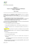
2. TDC-V4 board architecture
2.a. location of the main electronic components
connectivity for tests and next developments
time encoding
I/O connector
(SCSI-2 50p)
TDC oscillator
PCI bridge
PCI bridge
oscillator
RUN and BUSY LEDs
TDC-V4 – User Manual
6
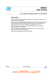
2.b. logical architecture
STOP0
in
Stop Coding Channel 0
enable
STOP1
in
Stop Coding Channel 1
enable
STOP15
FIFOChannel
FIFOChannel
multiplexing
in
Stop Coding Channel 15
enable
FIFOChannel
in
Start Coding Channel
enable
in
additional Coding Channel
(optional)
enable
FAST_START
FIFOChannel
FIFOChannel
Event Manager
Acquisition Manager
FIFO-ACQ
FIFO-ACQ
SLOW_START
PCI bridge
FIFO-Channel : - single buffer ; memory depth : 512 Time Encoding words
- buffers encoding words from a same Event
- a new Event cannot be accepted as long as the FIFO-Channel is not emptied of
the Encoding words of the previous Event. ; therefore several Events cannot
coexist in a FIFO-Channel.
2 x FIFO-ACQ : - double toggle buffering ; each memory depth : 509 words (32 bits)
in Event By Event Mode (EBE_HOST_ACK, EBE_TDC_AUTO et EBE_EXT_END),
stores Encoding or Service words from a same Event
in Accumulation Mode (ACC_TDC_AUTO), several Events may coexist in a
FIFO-ACQ buffer.
TDC-V4 – User Manual
7
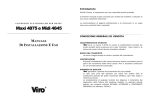
2.c. Inputs/Outputs (SCSI-2 50p connector)
SCSI-2 connector (front)
RUN output
50 25
Reserved output
ANALYSIS_GATE output
49 24
BUSY output
SLOW_START input
N
48 23
P
EXTERNAL_END input
N
47 22
P
STOP_GATE input
N
46 21
P
START_ENABLE input
N
45 20
P
+12v / 800mA
44 19
+12v / 800mA
GND
43 18
GND
STOP 0 input
N
42 17
P
STOP 1 input
N
41 16
P
STOP 2 input
N
40 15
P
STOP 3 input
N
39 14
P
STOP 4 input
N
38 13
P
STOP 5 input
N
37 12
P
STOP 6 input
N
36 11
P
STOP 7 input
N
35 10
P
STOP 8 input
N
34
9
P
STOP 9 input
N
33
8
P
STOP 10 input
9
STOP 11 input
N
N
N
32
7
P
31
6
P
STOP 12 input
N
30
5
P
STOP 13 input
N
29
4
P
STOP 14 input
N
28
3
P
STOP 15 input
N
27
2
P
FAST_START input
15
N
N
26
1
P
TTL
LVDS (slow signals)
LVDS (fast signals)
TDC-V4 – User Manual
8
3. Functions Modes
3.a. Event definition
An Event concerns all the information (Coding Words and Service Words) in relation to a
single physical action. Then, an Event may present a small number of words (for instance :
locating of a few particles after interaction), a large number of words (for instance : time of
flight mass spectrometry) or a very large number of words (for instance : "cold atoms"
experiments).
On a logical point of view, an Event is specified by :
a Trigger signal (TRIGGER)
an Analysis duration (ANALYSIS)
an Acknowledgment signal (ACKNOWLEDGE)
an Acquisition Mode.
Between TRIGGER and ACKNOWLEDGE signals, TDC-V4 is in the Busy state: it cannot
collect a new Event. The Busy state = 1 is displayed by a LED on the printed circuit and on the
front panel of ISIBox Interface.
Event processing is represented by the following chronogram.
TRIGGER
FAST_START
SLOW_START
HOST_START
RUN
ANALYSIS
INTERNAL_GATE
EXTERNAL_END
/TRIGGER
/RUN
ACKNOWLEDGE
HOST_ACK
EXTERNAL_END
AUTO
FORWARD_GATE
BACKWARD_GATE
ANALYSIS
BUSY
TDC-V4 – User Manual
9
3.b. Acquisition Modes
Each Coding Channel has a single buffer with 512 words depth FIFO-Channel memory
and all FIFOs are empty at the trigger time of a new Event. So, except for Events presenting
very large Stop rate, a Channel may not sustain losses due to the Stop rate on another
channel.
Output data from FIFO-Channels of the Start and Stop Coding Channels are multiplexed
and stored into one of the two FIFO-ACQ output buffers which operate in toggle buffering
mode, as signals are encoded as soon as Analysis Duration begins (see chapter 2.b : logical
architecture).
The multiplexing mechanism gives an equal access probability for all the Channels ; only
the first encoding on the Start Coding Channel has priority. This mechanism ensures that a
Channel with a large Stop rate does not result in losses on a Channel with a low Stop rate. In
the FIFO-ACQ output buffers, chronological order is for the encoding words coming from a
same Channel ; it may be not maintained among the encoding words coming from separate
Channels.
Whichever the selected data collecting mode (see below), the quantity of data making
up an Event is unlimited : the acquisition software is called each time a FIFO-ACQ output
buffer has data to output and is informed of the quantity of relevant data (≤ 509 words of 32
bits).
After the last word related to an Event (that is to say the EOE Service Word) is stored in
one of the two FIFO-ACQ output buffers, TDC-V4 proposes two main data collecting modes :
Event by Event collecting Mode
Accumulation collecting Mode
Event by Event collecting Mode
The acquisition software is informed that a data table is ready for reading and is
informed of the quantity of the available relevant data (≤ 509 words of 32 bits). TDC-V4
waits for Event Acknowledgment (see chapter 3.f : Acknowledgment Modes) before
accepting a new Trigger.
Due to the acquisition system latency, this regulating mode is not very rate effective and
is all the less effective because the size of the Event is small (see chapter 10 : data collecting
mean rate). Nevertheless, this regulating mode must be used if TDC-V4 is correlated with
other encoding devices, because all the other data sources making up an Event must be
collected by the acquisition software before TDC-V4 is allowed to encode a new Event.
TDC-V4 – User Manual
10
Accumulation collecting Mode
TDC-V4 self-acknowledges the Event in progress and is ready to accept a new Trigger.
Then, TDC-V4 accumulates the data in succession into FIFO-ACQ output buffers the data
related to the successive Events.
This regulating mode is more effective from mean rate point of view and is all the more
effective because the size of the Event is small (see chapter 10 : data collecting mean rate). It
is suitable for setups which have the TDC-V4 as the only data source.
Particular Accumulation collecting Mode : Continuing Analysis
In this configuration, TDC-V4 no longer filters signals by means of Trigger, Analysis
Duration and Acknowledgment : all the signals occurring at the input of the validated Start
and Stop Channels are encoded from a single Trigger instant and during the entire time the
TDC-V4 remains in state Run = ON.
For instance, if Trigger is selected with TRIGGER_SOURCE = RUN + HOST_START (see
chapter 3.c : Trigger Modes), the whole Run is logically considered as an unique Event with
an infinite Analysis Duration, all the signals are encoded during duration of the Run and all
the encoding results are stored in succession in the FIFO-ACQ output buffers.
This collecting Mode is the more effective from rate point of view (see chapter 10 : data
collecting rate) because filtering of the data and Event building are assigned to the
acquisition software.
This collecting Mode is chosen by selecting FORWARD_MODE = EXTERNAL_GATE with no
signal present in the EXTERNAL_END input.
TDC-V4 – User Manual
11
3.c. Trigger Modes
An Event can be triggered from 4 sources :
either of the FAST_START or SLOW_START input signals; if the ISIBox Interface
is used, FAST_START is a NIM signal and SLOW_START is a TTL signal
HOST_START command ; this Trigger Mode may be used for tests or in order to
measure physical backward noise by random sampling
RUN command ; this Trigger Mode may be used to trigger the Continuing
Analysis collecting Mode mentioned above without the necessity to generate a
signal neither by hardware or by software.
Moreover, Trigger can be validated or inhibited by the START_ENABLE input signal.
Trigger sources are represented on the following figure :
D
START_ENABLE
EVENT
TRIGGER_ENABLE
CLK
FAST_START
SLOW_START
HOST_START
TRIGGER
RUN
TRIGGER_SOURCE
Trigger Modes are controlled by the following registers :
name
TRIGGER_SOURCE
TRIGGER_ENABLE
TDC-V4 – User Manual
PCI
address
240 0000h
220 0000h
data
21
0
0
1
1
25
0
0
20
0
1
0
1
24
1
0
source
reserved
FAST_START
SLOW_START
RUN + HOST_START
enabling
START_ENABLE as Enable On
START_ENABLE as Enable Off
12
3.d. Analysis Durations
FORWARD ANALYSIS
Once the Event is triggered, signals entering into Coding Channels are encoded during a
duration beginning immediately after the trigger instant and lasting according to one among
the 4 following Forward Modes :
a preset time inside TDC-V4 (INTERNAL_GATE)
the EXTERNAL_END input (EXTERNAL_GATE)
the first of the two signals : EXTERNAL_END input or preset time inside TDCV4 (EXTERNAL_GATE / WATCHDOG)
the duration of TRIGGER signal itself
The last Analysis Duration Mode is the easiest to adjust precisely the analysis duration :
for instance, select FAST_START as trigger source and adjust the duration of the FAST_START
input signal.
An infinite FORWARD Duration is configured by selecting EXTERNAL_GATE mode and
suppressing any signal onto EXTERNAL_END input. Moreover, trigger an infinite duration
may be got without input signal by selecting TRIGGER_SOURCE = RUN + HOST_START (see
chapter 3.c).
TDC-V4 – User Manual
13
The FORWARD_MODE, and the FORWARD_DURATION if INTERNAL_GATE is selected,
are controlled by the following registers :
name
FORWARD_MODE
PCI
address
1C0 0000h
FORWARD_DURATION
1C0 0000h
TDC-V4 – User Manual
data
26
0
0
1
1
25
source
0
TRIGGER_GATE
1
INTERNAL_GATE
0
EXTERNAL_GATE
1
EXTERNAL_GATE / WATCHDOG
4 3 2 1 0
2 2 2 2 2
duration
180 ns
0
260 ns
1
340 ns
2
500 ns
3
660 ns
4
980 ns
5
1.3 µs
6
1.9 µs
7
2.5 µs
8
3.8 µs
9
5.1 µs
10
7.6 µs
11
10 µs
12
15 µs
13
20 µs
14
30 µs
15
41 µs
16
61 µs
17
82 µs
18
120 µs
19
160 µs
20
240 µs
21
320 µs
22
490 µs
23
650 µs
24
980 µs
25
1.3 ms
26
1.9 ms
27
2.6 ms
28
3.9 ms
29
5.2 ms
30
7.8 ms
31
14
BACKWARD ANALYSIS
TDC-V4 may encode Stop signals during a BACKWARD_DURATION before the trigger
time. This Mode avoids having to delay the Stop input signals occurring before the signal
used to trigger the event.
BACKWARD Mode and its Analysis Duration are controlled by the following registers :
name
BACKWARD_MODE
PCI
address
180 0000h
BACKWARD_DURATION 180 0000h
data
25
0
1
23 22 21 20
0
1
2
3
4
5
6
7
8
9
10
11
12
13
enabling
OFF
ON
duration
0 ns
0 ns
120 ns
240 ns
360 ns
610 ns
860 ns
1.3 µs
1.8 µs
2.8 µs
3.8 µs
5.7 µs
7.7 µs
11.6 µs
Notes :
If BACKWARD_MODE is disabled, TDC-V4 presents a short dead time between the Event
Trigger time and the time when the Stop Channels can encode (see Start Latency Time
chapter 9 : Technical Characteristics).
If BACKWARD_MODE is enabled and BACKWARD_DURATION = 0 ns, the Start Latency
Time = 0 ns.
BACKWARD_MODE does not operate with the Coding Start Channel.
TDC-V4 – User Manual
15
3.e. Coding Modes
Start Coding Channel: NEXT_START mode
The Start Coding Channel encodes the Event Trigger time. During data encapsulation,
the Encoding Word delivered by this Channel is automatically placed at the beginning of the
table of data relative to the Event, whether Backward Mode is used or not (see chapter 7 :
Data Encapsulation).
Data Encapsulation necessarily ends the table of data relative to an Event with the
Service Word EOE ; then, Coding Channel Start may, without chance of making a mistake
during Event Building, encode signals occurring after the trigger time. We call these Next
Starts signals.
In NEXT_START mode, TDC-V4 permits to select as Next Start one of the 3 following
signals (see diagram on next page) :
FAST_START
SLOW_START
FORWARD_GATE
In this way, if Interface ISIBox is used, TDC-V4 can operate the 4 following set up :
Trigger
signal
FAST_START
NIM
FAST_START
NIM
SLOW_START
TTL
SLOW_START
TTL
next signals
FAST_START
NIM
SLOW_START
TTL
FAST_START
NIM
SLOW_START
TTL
note
Event pile-up detection
Extra Stop encoding channel (TTL input)
Extra Stop encoding channel (NIM input)
Event pile-up detection
FORWARD_GATE source selection of the Next Starts permits to control the actual value
of the Analysis Duration, particularly if this duration is variable (EXTERNAL_GATE mode).
NEXT_START mode is controlled by the following register :
name
NEXT_START
TDC-V4 – User Manual
PCI
address
220 0000h
data
21
0
0
1
1
20
0
1
0
1
Next Start source
OFF
FAST_START
SLOW_START
FORWARD_GATE
16
Operating in NEXT_START mode
NEXT_START
FORWARD_GATE
FAST_START
Start
Coding Channel
in
SLOW_START
HOST_START
RUN
TRIGGER_SOURCE
D
Q
EVENT
CLK
Start Coding Channel: EVENT_LABELLING
The state of the START_ENABLE input signal at the Trigger instant can be stored and
reported into the Start Coding Word (bit EL ; see chapter 6 : Data Format).
This function is controlled by the following register :
name
EVENT_LABELLING
TDC-V4 – User Manual
PCI
address
220 0000h
data
25
1
1
24
1
0
enabling
START_ENABLE as Label On
START_ENABLE as Label Off
17
Additional Coding Channel (optional)
This optional Channel encodes either of the two following input signals :
SLOW_START
EXTERNAL_END
If either SLOW_START or EXTERNAL_END is not used (Trigger by SLOW_START ; Analysis
Duration by EXTERNAL_END), the Additional Coding Channel permits to extend the number
of Coding Channels to 17 and, if Interface ISIBox is used, to encode a TTL input signal.
The Additional Coding Channel does not benefit from static or dynamic enabling
capabilities (see next paragraph).
Input signal selection is controlled by the following register :
name
EXTRA_CHANNEL
PCI
address
NA
data
20
0
1
input signal
SLOW_START
EXTERNAL_END
Stop Coding Channels: enabling
Coding Channels can be enabled or disabled :
statically for each Channel
dynamically for the whole 16 Channels by means of the STOP_GATE input
signal
Enabling of the Stop Coding Channels is controlled by the following registers :
name
STATIC_STOP_ENABLE
DYNAM_STOP_ENABLE
TDC-V4 – User Manual
PCI
address
120 0000h
220 0000h
data
2i
0
1
23
0
1
static enabling of i channel
OFF
ON
enabling by STOP_GATE
OFF
ON
18
Stop Coding Channels: Overflow
TDC-V4 empties the FIFO-Channel memory of each Channel as soon as Forward Analysis
begins. If the rate of the experiment is larger than the rate of the data collecting system, the
FIFO-Channel of a Channel may overflow.
In this case, the FIFO-Channel of this Channel becomes "Full" and the first Coding Word
which will be delivered by the Channel is stamped in his Label Field by means of the bit OF
(see chapter 6 : Data format).
Service Channel Range Extension REXT (optional)
TDC-V4 delivers Coding Words and Service Words, 32 bits wide. These Words are
composed with 2 fields (see chapter 6 : Data format) :
DATA field, 26 bits wide
LABEL field, 6 bits wide.
The DATA field extends the maximum range of the Coding Channels to 226 x 120 ps = 7.8
ms.
Implementation of the unique Service Channel Range Extension permits to extend
beyond 7.8 ms the time range of all the 32 bits wide Coding Channels. The DATA extension
beyond 26 bits has to be processed by the acquisition software.
The Service Channel Range Extension is not provided with a FIFO-Channel memory.
Stop Coding Channels: RESOLUTION/DNL optimization
TDC-V4 provides a mechanism in order to optimize either the Resolution figure (at the
expense of the DNL characteristics) or the DNL characteristics (at the expense of the
Resolution figure) ; this optimization is valid overall for all the Coding Channels (with or
without Range Extension).
This optimization is controlled by the following register :
name
OPTIMIZATION
PCI
address
220 0000h
data
22
0
1
Optimized characteristic
RESOLUTION
DNL
Note 1 : Differential Non Linearity (quantifies the actual bins width inequality)
TDC-V4 – User Manual
19
3.f. Acknowledgment Modes
Possibilities of Event Acknowledgment according to the suitable Acquisition Mode for
the experiment are presented on the following table :
Acquisition
Mode
Acknowledgment
Mode
EBE_HOST_ACK
EBE_EXT_END
Event by Event
EBE_TDC_AUTO
Accumulation
ACC_TDC_AUTO
TDC-V4 supplies to the acquisition software
processor only the data relative to one Event and
enables a new Trigger after it is acknowledged by
the acquisition software by means of the
command HOST_ACK.
TDC-V4 supplies to the acquisition software only
the data relative to one Event and enables a new
Trigger after it is acknowledged by means of the
command EXTERNAL_END.
TDC-V4 supplies to the acquisition software only
the data relative to one Event and enables a new
Trigger as soon as all the data relative to this Event
are stored into FIFO-ACQ output buffers. This
Acknowledgment Mode involves that the user
controls the Trigger signal in order to ensure the
correlation of all data sources making up the Event.
TDC-V4 piles up in succession into FIFO-ACQ
output buffer the data related to the successive
Events. Each Event is acknowledged automatically
as soon as all the data relative to an Event are
stored into FIFO-ACQ output buffers.
Acknowledgment Mode selection is controlled by the following register :
name
ACK_MODE
PCI
address
260 0000h
TDC-V4 – User Manual
data
21
0
0
1
1
20
0
1
0
1
mode
ACC_TDC_AUTO
EBE_TDC_AUTO
EBE_EXT_END (optional)
EBE_HOST_ACK
20
3.g. Modes of Function summary
default values
Trigger Modes
Analysis Duration
TRIGGER SOURCE
FAST_START
SLOW_START
RUN + HOST_START
TRIGGER ENABLE
START_ENABLE as Enable
FORWARD ANALYSIS
INTERNAL_GATE / duration table
EXTERNAL_GATE
EXTERNAL_GATE / WATCHDOG
TRIGGER_GATE
BACKWARD ANALYSIS / duration table
Start Coding Channel
NEXT_START
FAST_START
SLOW_START
FORWARD_GATE
EVENT_LABELLING
START_ENABLE as Label
Coding Modes
3-c
FAST_START
OFF
3-d
INTERNAL
(180ns)
OFF (0ns)
3-e
OFF
OFF
Additional Coding Channel (optional)
INPUT
SLOW_START
EXTERNAL_END
Stop Coding Channels
STATIC_STOP_ENABLE
DYNAM_STOP_ENABLE
all enabled
OFF
Service Channel Range Extension (optional)
Coding Channel Stop Overflow
RESOLUTION/DNL Optimization
Acknowledgment Modes
Data collecting
EBE_HOST_ACK
EBE_EXT_END (optional)
EBE_TDC_AUTO
ACC_TDC_AUTO
RESOLUTION
3-f
ACC_TDC_AUTO
Note :
Modes configuration registers access is write only.
TDC-V4 – User Manual
21
4. Commands
4.a. Init Commands
Function Modes Initialization
The Command is controlled by the following register :
name
INIT_CONF
PCI
address
140 0000h
data
20
0
1
command
OFF
ON
INIT_CONF = ON Command must be followed by INIT_CONF = OFF Command.
Be careful with this Command : after this Command executed, Function Modes get their
default values as described chapter 3.g and may not to correspond to the one displayed by
the Configuration utility program.
TDC-V4 logical state Initialization
The Command is controlled by the following register :
name
INIT_TDC
PCI
address
160 0000h
data
20
0
1
command
ON
OFF
INIT_TDC = ON Command must be followed by INIT_TDC = OFF Command.
TDC-V4 logical state is automatically initialized while TDC-V4 powering on.
TDC-V4 – User Manual
22
4.b. RUN Command
RUN Command carries out several functions :
in any case, RUN = ON enables Event Trigger
in the TRIGGER_SOURCE = RUN + HOST_START case (see chapter 3.c: Trigger
Modes), RUN = ON triggers an Event processing
in the infinite Forward Duration case (see chapter 3.d: Analysis Duration), RUN =
OFF ends the Analysis Duration
in any case RUN = OFF
disables Event Trigger
transfers to the acquisition software, if data collecting is not stopped, all
the data present in TDC-V4
closes the last data table with EOR Service Word (see chapter 6 : Data
Format).
The Command is controlled by the following register :
name
RUN
PCI
address
1A0 0000h
data
20
0
1
command
OFF
ON
RUN = ON state is displayed by means of a LED on the TDC-V4 printed circuit board as
well as on the ISIBox Interface front panel.
4.c. HOST_ACK Command
HOST_ACK Command is used by EBE_HOST_ACK Acknowledgment Mode (see chapter
3.f: Acknowledgment Modes) in order to regulate the Event By Event throughput.
The Command is controlled by the following register :
name
HOST_ACK
PCI
address
2C0 0000h
data
20
0
1
command
OFF
ON
HOST_ACK = ON Command must be followed by HOST_ACK = OFF Command.
TDC-V4 – User Manual
23
4.d. HOST_START Command
HOST_START command is used by TRIGGER_SOURCE = RUN + HOST_START Trigger Mode
(see chapter 3.c : Trigger modes).
The Command is controlled by the following register :
name
HOST_START
PCI
address
2E0 0000h
data
20
0
1
command
OFF
ON
HOST_START = ON Command must be followed by HOST_START = OFF Command.
Note :
Command registers access is write only.
TDC-V4 – User Manual
24
5. Service signals polarity selection
Selection of the polarity of each of the START_ENABLE, STOP_GATE, EXTERNAL_END and
SLOW_START input signals as well as of each of the ANALYSIS_GATE and BUSY output signals
is controlled by the following register :
name
POLARITY
PCI
address
280 0000h
data
25 24 23 22 21 20
x x x x x 0
polarity
START_ ENABLE input: active low
x x x x x 1
START_ENABLE input: active high
x x x x 0 x
STOP_GATE input: active low
x x x x 1 x
STOP_GATE input: active high
x x x 0 x x
EXTERNAL_END input: active low
x x x 1 x x
EXTERNAL_END input: active high
x x 0 x x x
SLOW_START input: active low
x x 1 x x x
SLOW_START input: active high
x 0 x x x x
BUSY output: active low
x 1 x x x x
BUSY output: active high
0 x x x x x
ANALYSIS_GATE output: active low
1 x x x x x
ANALYSIS_GATE output: active high
Note :
If ISIBox Interface is used, the state of Busy LED in front panel depends on the selected
polarity for BUSY signal (Lemo00 in front panel) :
if BUSY signal is active high, the LED is ON while TDC-V4 is in Busy state
if BUSY signal is active low, the LED is OFF while TDC-V4 is in Busy state.
Note :
Polarity Selection registers access is write only.
Polarity Selection default values are in Active high state.
TDC-V4 – User Manual
25
6. Data Format
TDC-V4 delivers Coding Words and Service Words. The 32 bits wide Word decomposes
into 2 fields :
26 bits wide DATA field
6 bits wide LABEL field.
The 6 bits wide LABEL field permits 64 various Labels, thus to distinguish 64 data sources.
Among these 64 Labels, 50 Labels are allotted and are listed on the table next page :
bold type Labels are allotted to data source types developed in the TDC-V4 version
described in this User Manual
dimmed Labels are allotted to data source types which may be developed in
accordance with the user's needs
The last 14 Labels are available for exotic data sources as Counting Scale, Rate meter,
ADC, QDC, … .
TDC-V4 – User Manual
26
LABEL
FUNCTION
DATA
231 230 229 228 227 226
0 n n n n m
0 n n n n n
1 0 0 0 0 EL
- TDC 16 Stop Channels / 1 word encoding with mark
nnnn = Channel number
m = OF (OverFlow FIFO-Channel)
- TDC 16 Stop Channels / 2 words / duration
nnnn = Channel number
m = 0 rising edge ; m = 1 falling edge
- TDC 16 Stop Channels / 2 words / high resolution
nnnn = Channel number
m = 1 MSB's ; m = 0 LSB's
- TDC 32 Stop Channels / 1 word encoding
nnnnn = Channel number
- Start Channel / 1 word encoding with mark
EL = START_ ENABLE input as Label (unless EL = 0)
225 224 ….. 21 20
absolute time
absolute time
absolute time
absolute time
absolute time
1 0 0 1 0 1
- Additional Channel / 1 word encoding
absolute time
1 0 0 0 1 EL
- Start Channel / 2 words encoding with mark / MSB's
EL = START_ ENABLE input as label (unless EL = 0)
absolute time
1 0 0 1 0 0
- Start Channel / 2 words encoding / LSB's
absolute time
1 0 0 1 1 m
1 1 1 0 0 m
1 1 0 0 0 0
1 1 0 0 1 m
1 1 0 1 0 m
- Additional Channel / 2 word encoding
m = 1 MSB's ; m = 0 LSB's
- REXT (Range Extension)
m = 0 1st semi-period 7.8 ms
m = 1 2nd semi-period 7.8 ms
- EOE (End Of Event) / 1 word
absolute time
(count)*
free
- EOE-N (End Of Event / Event Number) / 2 words
m = 1 MSB's
m = 0 LSB's
- EOE-T (End Of Event / Event Time) / 2 words
m = 1 MSB's
m = 0 LSB's
event number
time flag
1 1 0 1 1 0
- SOR (Start Of Run)
(run number)
1 1 0 0 0 1
- EOR (End Of Run)
(run number)*
1 1 0 1 1 0
- EOS (End Of Source)
source number
* to be specified
Coding Channel
Temps
TDC-V4 – User Manual
Service Channel
27
7. Data Encapsulation
Data encapsulation is independent of any Function Mode.
Data relatives to an Event and delivered by Stop Channels, Start Channel (if NEXT_START
mode is selected), Additional Channel (if the option is implemented) and Range Extension
Service Channel (if the option is implemented) are bulked into an unique table (which may
be shared between consecutive buffers according to the Event size and the Acquisition
Mode) and are enclosed with the two following words :
at the head of the table : the Start Channel Word encoding the Trigger instant
at the rear of the table : EOE (End Of Event) Service Word.
The illustration below presents an example of Data Encapsulation :
TRIGGER
signals entering in Start Channel
NEXT_START
(First
START_
WORD)
OR'ed signals entering in Stop Channels
(0)
(1) (2)
(3) (4) (5)
(6)
(7)
(8)
FORWARD_GATE
START_WORD
STOP_WORD (1)
STOP_WORD (2)
STOP_WORD (3)
STOP_WORD (4)
STOP_WORD (5)
START_WORD (*)
STOP_WORD (6)
STOP_WORD (7)
EOE_WORD
(*) if NEXT_START mode is selected
TDC-V4 – User Manual
28
Notes :
Chronological order of encodings of the signals entering a same Channel is restored
after encapsulation.
Chronological order of encodings of the signals entering different Channels is not
maintained after encapsulation.
Chronological order of encodings of the signals entering Start Channel with
NEXT_START mode selected is restored after encapsulation. The first encoding word
delivered by Start Channel is distinguished from the following ones because it is at
the beginning of the Run or because it is directly preceded with EOE Service Word.
Illustration below shows that Data Encapsulation is unchanged if BACKWARD_MODE
mode is selected :
TRIGGER
signals entering in Start Channel
NEXT_START
(First
START_
WORD)
OR'ed signals entering in Stop Channels
(0)
(1) (2)
(3) (4) (5)
(6)
(7)
(8)
BACKWARD_GATE
FORWARD_GATE
ANALYSIS1
START_WORD
STOP_WORD (1)
STOP_WORD (2)
STOP_WORD (3)
STOP_WORD (4)
STOP_WORD (5)
STOP_WORD (6)
START_WORD2
STOP_WORD (7)
EOE_WORD
Note 1 : ANALYSIS_GATE output signal is high during FORWARD_GATE
Note 2 : if NEXT_START mode is selected
After RUN = OFF Command, EOR Service Word is delivered to the acquisition
software after the last data table of the last Event processed by TDC-V4.
TDC-V4 – User Manual
29
8. Data collecting through PCI Bus
Collecting of the data delivered by TDC-V4 operates by means of the 3 following registers
(the PCI address values are different with TDC-V4 version compatible with Narval acquisition
software) :
SEMAPHORE register (read and write)
name
SEMAPHORE
PCI
data
address
2AFC04h 231… 216 215… 24 23 22 21 20
X … X 0 … 0 0 1 0 0 available buffer : no
n … n 0 … 0 0 1 1 0 available buffer: yes
n … n : Size
Reset of SEMAPHORE register is made by writing 4h.
SIZE (read only)
name
SIZE
PCI
address
2AFC08h
data
231… 216 215 … 20
0 … 0
n … n
n … n : Size
DATA (read only)
name
DATA
PCI
address
2AFC18h
data
231 … 20
d … d
d … d : Data
The 2 FIFO-ACQ output buffers of TDC-V4 operate as double buffering. When a buffer is
said available ?
If Event By Event Acquisition Mode is selected (EBE_HOST_ACK, EBE_EXT_END or
EBE_TDC_AUTO), a buffer is available if :
the FIFO memory in progress is full (509 words)
or EOE (End of Event) Service Word is stored
or EOR (End of Run) Service Word is stored.
If Accumulation Acquisition Mode is selected (ACC_TDC_AUTO), a buffer is
available if :
the FIFO memory in progress is full (509 words)
or EOR (End of Run) Service Word is stored.
TDC-V4 – User Manual
30
The acquisition software accesses to SEMAPHORE, i.e. to the information "buffer is
available", can be done by means of :
interrogation of the content of SEMAPHORE register (polling)
treatment of hardware interruption (INTA Interruption line of PCI Bus)
For either these 2 access modes (Polling or Interruption), TDC-V4 is compatible with 2
possible data collecting protocols :
Standard Protocol, the most often used with previous TDC versions
Simplified Protocol, allowing rate increasing in Event By Event Acquisition Mode.
Standard Protocol
Interruption
Polling
Buffer Read
function
INTA treatment
Read
SEMAPHORE
available
buffer ?
no
yes
Read
SIZE
(N = Size)
Read
SIZE
(N = SIZE)
N times
Read
DATA
N times
Read
DATA
reset
SEMAPHORE
reset
SEMAPHORE
End
function
End
interruption
TDC-V4 – User Manual
31
Simplified Protocol
By Polling access, the Simplified Protocol suppresses :
the reading of SIZE register (the protocol uses the SIZE field of SEMAPHORE
register)
the Reset by writing into SEMAPHORE register.
By Interruption access , this protocol suppresses :
the Reset by writing into SEMAPHORE register.
Polling
Interruption
Buffer Read
function
INTA treatment
Read
SEMAPHORE
available
buffer ?
yes
TDC-V4 – User Manual
no
N = SIZE
Read
SIZE
(N = SIZE)
N times
Read
DATA
N times
Read
DATA
End
function
End
interruption
32
9. Technical Characteristics
with ISIBox rack
time bin
120 ps
resolution (σ)
60 ps
double hit resolution (max)
isolated
in burst (max)
in burst (mean)
latency after Trigger
without backward mode
with backward mode
2.5 ns
5 ns
4 ns
4 ns
0 ns
INL
0%
DNL
4%
range
without REXT
with REXT (optional)
7.8 ms
boundless
input buffer per channel
512 words
output buffer
2 x 509 words
time encoding channels
Start
Stop
Additional (optional)
1
16
1
SCSI input/output level
LVDS
monitoring outputs
control inputs
trigger sources
analysis gate
acquisition modes
PCI handshake
TDC-V4 – User Manual
RUN
BUSY
FORWARD_GATE
TRIGGER_ EN. / EVENT_LABEL.
STOP_GATE
EXTERNAL_END
FAST_START
SLOW_START
HOST
INTERNAL
EXTERNAL
BACKWARD
boundless
EVENT BY EVENT
ACCUMULATION
POLLING
INTERRUPTION
NIM / ECL
TTL and displayed
TTL and displayed
TTL
TTL
TTL
TTL
NIM
TTL
33
10.
Data collecting rates
Data collecting rate depends on many parameters : power, architecture and operating
system of the acquisition computer, data processing software, Event rhythm (periodic,
Poisson), Event feature (fixed size, variable size, Analysis Duration), data losses, etc.
Moreover, data collecting rate depends strongly on selected Acquisition mode and
Acknowledgment Mode (see chapters 3.b and 3.f). This chapter clarifies the 3 modes
(Continuing Analysis ; Accumulation ; Event By Event) and presents the measured rate
performances.
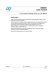
10.a. the 3 data collecting methods
Continuing Analysis
With this method, all the enabled signals are encoded since TDC-V4 is triggered (only
one Trigger signal is sufficient) (see chapter 3.c) up to the Run reset. Resulting data are
piled up continuously into double buffering FIFOs.
Continuously Analysis Mode is chosen by selecting EXTERNAL_GATE as Analysis
Duration and by suppressing any signal on the EXTERNAL_END input: so, TDC-V4 runs
with an infinite Analysis Duration (see chapter 3.d).
Thus, the whole Run is considered as a unique Event, either Event By Event Mode or
Accumulation Mode may be equally selected (see chapter 3.f). In the same way, it does
not make sense to select BACKWARD_MODE.
If all the signals entering the Start Coding Channel, NEXT_START mode must be
selected (see chapter 3.e).
Data flow is framed by the Start Coding Word at the Run beginning and the EOE + EOR
Service Words at the end. Except the last buffer of the Run, all buffers contain 509
Words 32 bits wide.
Continuing Analysis Mode is the most efficient one from a rate point of view. TDC-V4
operates no filtering on the input signals and no Event building ; these operations have
to be processed by the acquisition software.
TDC-V4 – User Manual
34
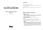
Accumulation
With this method, each Trigger induces a Forward Analysis Gate with finite Duration
(180 ns minimum, 7.8 ms maximum) and TDC-V4 accumulates the encodings relative to
successive Events into the output buffer.
For each Event, TDC-V4 gathers encodings occurring during the Backward Analysis
Gate (if BACKWARD_MODE is selected, see chapter 3.d) and during the Forward Analysis
Gate. TDC-V4 frames Stop Channels encodings (and Start Channel encodings if
NEXT_START is selected, see chapter 3.e) with Start Coding Word at the beginning of the
Event table and with EOE Service Word at the end of the Event table.
In Accumulation Mode, the data processing software is simpler than in Continuing
Analysis Mode but collecting rate is decreased.
Except the last buffer of the Run, all buffers contain 509 Words 32 bits wide.
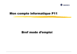
Event By Event
With this method, each Trigger induces a Forward Analysis Gate with finite Duration
(180 ns minimum, 7.8 ms maximum), TDC-V4 gathers encodings occurring during the
Backward Analysis Gate (if BACKWARD_MODE is selected, see chapter 3.d) and during
the Forward Analysis Gate and waits for Acknowledgment before enabling a new
Trigger. Only in EBE_TDC_AUTO mode (see chapter 3.f), TDC-V4 is self-acknowledged.
TDC-V4 frames Stop Channels encodings (and Start Channel encodings if NEXT_START
is selected, see chapter 3.e) with Start Coding Word at the beginning of the Event table
and with EOE Service Word at the end of the Event table.
The size of the buffers read by the acquisition software is variable, between 2 and
509 words 32 bits wide.
Event By Event Mode must be used if TDC-V4 has to be correlated with other data
sources. This Mode is the least efficient from rate point of view, especially since the
mean number of Stops per Event is small.
TDC-V4 – User Manual
35
10.b. maximum rate without losses
The conditions of the measurement are as it follows :
central unit : multi-cores PC
operating system : Windows XP
data processing : none
Event rhythm : periodic
Event size : fixed : 1 Start + n Stops
losses ratio : 0%
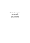
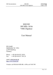
Continuing Analysis data collecting
6
maximum rate without losses (10 /sec)
16
15
15.1
14.7
14
13.9
13
12.5
12
11.7
11
Stops/seconde
10.4
10
9
8
7.8
7
6
5.2
5
4
Events/seconde
3.9
3.1
3
1.7
2
0.9
1
0.5
n Stops/Event
0
1
2
3
4
8
16
32
without losses rate, periodic frequency, according to Event size
Mode : Continuing Analysis
TDC-V4 – User Manual
36
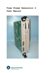
ACCUMULATION data collecting
6
maximum rate without losses (10 /sec)
13
12
11
10
9
Stops/seconde
8
7
6
5
4
3
Events/seconde
2
1
n Stops/Event
0
1
2
3
4
8
16
32
without losses rate, periodic frequency, according to Event size
Acknowledgment Mode : ACC_TDC_AUTO INTERNAL_GATE : 180 ns
mean number of
Stops per Event
1
without losses rate
MegaEvents/sec
1.25
without losses rate
MegaStops/sec
1.25
2
1.25
2.5
3
1.25
3.75
4
1.1
4.4
8
0.8
6.4
16
0.6
10.0
32
0.4
12.8
TDC-V4 – User Manual
37
Event By Event data collecting
3
maximum rate without losses (10 /sec)
2 000
1000
500
Stops/seconde
250
125
60
Events/seconde
30
15
n Stops/Event
1
2
3
4
8
16
32
without losses rate, periodic frequency, according to Event size
Acknowledgment Mode : EBE_HOST_ACK or EBE_TDC_AUTO
INTERNAL_GATE : 180 ns
mean number of
Stops per Event
without losses rate
KiloEvents/sec
without losses rate
KiloStops/sec
1
91.3
91.3
2
90.5
181
3
89.7
269
4
88.9
356
8
85.8
687
16
80.3
1285
32
71.2
2280
TDC-V4 – User Manual
38
11.
TDC-V4 installation
11.a. required configuration
Installation of TDC-V4 board as well as associated Driver and DLL needs a PC type
computer with the following minimum characteristics :
Processor : compatible Pentium® 1 GHz
RAM memory: 256 Mo
Hard disk : 10 Mo free
One free slot PCI 32 bits or 64 bits wide with a 3.3V supply (PCI certification)
Operating System : Windows
11.b. installation
Installation of the board into the PC :
Turn off the computer and unplug the supplied cable
Remove the PC cover
Choice a free PCI slot (white color slots) ; if a filling bracket shuts the slot on the PC
rear panel, remove it
Insert the TDC-V4 board all the way in, holding the board edges firmly
Check that the board is well straight and hold the TDC-V4 bracket with the supplied
screw
Replace the computer cover and the supplied cable.
Installation of the driver (Windows XP) :
Start the computer
If the Found new hardware wizard window appears, click Cancel
Install the driver by launching the drv_install.exe program contained in the
Installation Driver folder of the supplied Package TDC-V4, then follow the
instructions.
Checking that TDC-V4 is recognized by Operating System :
Click Start, then Control panel, System, and finally Device manager
Double click Jungo (driver supplier), then IT001 (TDC-V4 card name).
Properties window opens and a message displays the device state. Check that This device is
working properly message is displayed.
icon next to IT001 informs that TDC-V4 board is
not properly installed.
TDC-V4 – User Manual
39
12.
DLL Functions
This chapter helps to use DLL Functions supplied with TDC-V4 board for C/C++ software.
This DLL was developed by ISITech company and TDC-V4 is compatible with it. An optimized
DLL will be developed later.
12.a. required files
For C/C++ software, the following files enclosed in the DLL folder of the TDC-V4 Package,
must be included into the program :
isitime_dll.dll : DLL file
import_dll.h : header file
isitime_dll.lib : resource file
12.b. functions
Driver opening :
Void OuvertureDriver(char *flag, unsigned long vID, unsigned long dID, int mc)
To be used during each program launching. This function needs the following parameters :
flag returns the value 20 if the function is successful
vID = 0x10B5
dID = 0x5406
mc = -1
Driver closing :
Void FermetureDriver()
To be used during each program exit.
Writing into a register :
Bool Data_Ecriture(int *buffer, int taille, unsigned long adresse, int mode)
To be used to write into the Mode and Command registers :
buffer : data word (32 bits wide)
size = 1
address : report to summary chapter 14
mode = 6
TDC-V4 – User Manual
40
Reading from a register :
Bool Data_Lecture(int *buffer, int taille, unsigned long adresse, int mode)
To be used to read one among the 3 registers DATA, SEMAPHORE and SIZE :
buffer : data word (32 bits wide)
size : number of words to read
address : report to summary chapter 14
mode = 3 for DATA register; 0 for the other registers
Data reading from the FIFO-ACQ output buffers:
int Read_dsp_bis(int *data_buffer, int *size)
To be used to read the data buffer available in the TDC-V4 output buffers with the standard
protocol. This integrated function manages :
reading from SEMAPHORE register
test of data availability :
if data are not available : the function returns 0
if data are available : the function reads size from TDC-V4 SIZE register, reads the
suitable number of data from the TDC-V4 output buffers, resets the SEMAPHORE
register, returns 6 and assigns the following contents :
data_buffer : read data (32 bits wide table)
size : number of read words (≤ 509)
TDC-V4 – User Manual
41
13.
Program example
The following example clarifies the chronological architecture to be respected by any
acquisition software (standard protocol).
1. Driver opening
Use OuvertureDriver function
Syntax example :
char flag = 0;
OuvertureDriver(&flag, 0x10B5, 0x5406, -1);
2. Initialization (not necessary before a Run launching)
Use Data_Ecriture function
Syntax example :
#define INIT_TDC 0x1600000
int register_val = 0;
Data_Ecriture(®ister_val, 1, INIT_TDC, 6); // Reset TDC asserted
register_val = 1;
Data_Ecriture(®ister_val, 1, INIT_TDC, 6); // Reset TDC de-asserted
Caution : Reset TDC must be a pulse ; de-assertion must follow assertion.
3. Configuration (may be operated at any time)
Use Data_Ecriture function
Syntax example : static enabling of Stop1 and Stop3 Channels, static disabling of the
other Stop Channels (keeps the other registers to their default values) :
#define STATIC_STOP_ENABLE 0x1200000
register_val = 0xA; // binary: 1010
Data_Ecriture(®ister_val, 1, STATIC_STOP_ENABLE, 6);
4. Run launching
Use Data_Ecriture function
Syntax example :
#define RUN 0x1A00000
register_val = 1;
Data_Ecriture(®ister_val, 1, RUN, 6);
TDC-V4 – User Manual
42
5. Data collecting (standard protocol)
Use Read_dsp_bis function
Syntax example :
int size, data_buffer[509], status = 0;
// Acquisition loop during the wanted duration
while(status == 0 ) // Data available polling test
{
status = Read_dsp_bis(data_buffer, &size)
}
6. Run ending
Use Data_Ecriture function
Syntax example :
register_val = 0;
Data_Ecriture(®ister_val, 1, RUN, 6);
7. Data collecting ending
In order to be sure that all the encodings remaining in the TDC-V4 buffers after the
Run ending are read, data collecting should continue until the EOR Service word is
detected.
8. Driver closing
Use FermetureDriver function
Syntax example :
FermetureDriver();
A functional example of C++ program is available in the Example program folder of
the TDC-V4 package.
TDC-V4 – User Manual
43
14.
TDC-V4 registers summary
name
address
page
CONFIGURATION REGISTERS
TRIGGER_SOURCE
TRIGGER_ENABLE
FORWARD_MODE
FORWARD_DURATION
BACKWARD_MODE
BACKWARD_DURATION
NEXT_START
EVENT_LABELLING
EXTRA_CHANNEL
STATIC_STOP_ENABLE
DYNAM_STOP_ENABLE
OPTIMIZATION
ACK_MODE
INIT_CONF
INIT_TDC
RUN
HOST_ACK
HOST_START
POLARITY
240 0000h
220 0000h
1C0 0000h
1C0 0000h
180 0000h
180 0000h
220 0000h
220 0000h
NA
120 0000h
220 0000h
220 0000h
260 0000h
140 0000h
160 0000h
1A0 0000h
2C0 0000h
2E0 0000h
280 0000h
12
12
14
14
15
15
16
17
18
18
18
19
20
22
22
23
23
24
25
COMMAND REGISTERS
SEMAPHORE
SIZE
DATA
TDC-V4 – User Manual
2AFC04h
2AFC08h
2AFC18h
30
30
30
44