1
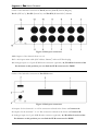
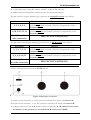
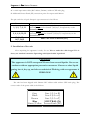
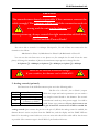
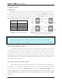
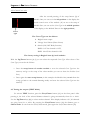
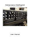
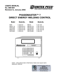
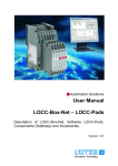
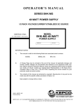
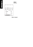
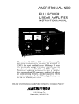
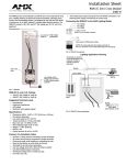
Pegasus® Pro series
12 x 2.3 kW Digital Dimmer
User’s manual
Fifth edition
Copyright 2008
Pegasus ® Pro Series Dimmer
Dear Customer!
Thank you for chose PLS Electronics product. Please read this manual carefully. If you
have any technical question or you looking for other equipments, don’t hesitate to take up the
contact with our sales representative or with the manufacturer at the www.pls.hu web site.
This apparatus is a twelve channel digital dimmer with DMX 512/1990 or 0-10V control
(optional) with additional control possibilities. The light control is produced by a phase angle
control system (on the neutral).
The wrapper of the unit is NOT baby toy
therefore keep it away form babies!
For technical questions and
please take up the contact
with our sales representative or with the manufacturer at the
www.pls.hu web site.
ATTENTION!
DON’T USE WITHOUT PROTECTIVE GROUND!
Not allowed to make a parallel connection between
any outputs (phases or neutrals) of the unit!
Otherwise the unit can be damaged!
2
PLS Electronics Ltd.
Front parts
1A,B,C Phase / Module state indicators. If it’s ON,
the corresponding phase unit is working.
2A,B,C PreHeat/Curve setup button of Module 1, 2
and 3. See the operation later.
3. Circuit breakers to protect the outputs.
4. These green LEDs show the control level of each
channel.
5. These yellow LEDs show the output level of each
channel.
6. DMX control LED ( If it’s flashing, the DMX
pocket is correct; when ON, the dimmer is in
Test, Chaser, PreHeat or Curve setup mode;
when OFF, the DMX pocket is incorrect, not
present or Analog control (optional) is on.)
7. DMX display. Here you can see basically the start
address of this apparatus on the DMX line.
8/9. Down / Up buttons. With them you can set
the DMX start address, Test channel, Chaser
program, PreHeat level or the Control curve
depends on the dimmer state.
10. Test/Chaser button. If you push one time the
selected channel of the dimmer is increasing
automatically from 0% to 100%. If the display
indicates “00”, all channels are go 0% to 100%.
By pressing this button again the dimmer goes to
Chaser mode (see later). Push the Test button
again, and the dimmer goes back to normal
dimming operation.
11. DMX input via male XLR connector.
12. DMX throughput via female XLR connector
13. 120 Ohm DMX line termination switch. Switch
it to ON position only if this unit is the last on
Figure 1. Handling units of front part
the DMX line! Otherwise left it in OFF position!
3
Pegasus ® Pro Series Dimmer
Outlet of the backside connectors at Pro-S (Schuko), Pro-F (French/Belgian),
Pro-C (CEE16/3), Pro-PC (PowerCon) and Pro-WL (Wieland ST17) dimmer
Figure 2. Back part connectors
1-12. Outputs of the channels from 1 to 12.
13. 3 x 40A input mains cable (H07 rubber; 5x6mm2) without CEE male plug
14. Analogue input via 15 pole SUB-D male connector (optional). At /B suffixed version of the
Pro dimmer at this position you can find the XLR connectors for DMX!
Outlet of the backside connectors at Pro-H2 dimmer:
Figure 3. Back part connectors
1. Outputs for the channels 1 to 6. This connector referred in the future as Connector A.
2. Outputs for the channels 7 to 12. This connector referred in the future as Connector B.
3. Analogue input via 15 pole SUB-D male connector (optional). At /B suffixed version of the
Pro dimmer at this position you can find the XLR connectors for DMX!
4
PLS Electronics Ltd.
4. 3 x 40A input mains cable (H07 rubber; 5x6mm2) without CEE male plug
5. Additional Protect Earth (PE) connection point for outputs with M4 nut
The pin outlet the 16-pole ‘Harting’ type connectors in normal H2 version is the follows:
Pin number
1, 2, 3, 4, 5, 6
9, 10, 11 12, 13, 14
7, 8, 15, 16 and the
side connectors
Function
Output phases for channel 1,2,3,4,5,6 respectively at Connector A
and output phases for channel 7,8,9,10,11,12 respectively on the
Connector B.
Output neutrals for channel 1,2,3,4,5,6 respectively at Connector A
and output neutrals for channel 7,8,9,10,11,12 respectively on the
Connector B.
PROTECTIVE EARTH (PE)
The pin outlet of the 16-pole ‘Harting’ type connectors in H2-D version is the follows:
Pin number
1, 3, 5, 7, 9, 11
2, 4, 6, 8, 10, 12
13, 14, 15, 16 and
the side connectors
Function
Output phases for channel 1,2,3,4,5,6 respectively at Connector A
and output phases for channel 7,8,9,10,11,12 respectively on the
Connector B.
Output neutrals for channel 1,2,3,4,5,6 respectively at Connector A
and output neutrals for channel 7,8,9,10,11,12 respectively on the
Connector B.
PROTECTIVE EARTH (PE)
Outlet of the backside connectors at Pro-SX dimmer:
Figure 4. Back part connectors
1. Outputs for the channels 1 to 6. This connector referred in the future as Connector A.
2. Outputs for the channels 7 to 12. This connector referred in the future as Connector B.
3. Analogue input via 15 pole SUB-D male connector (optional). At /B suffixed version of the
Pro dimmer at this position you can find the XLR connectors for DMX!
5
Pegasus ® Pro Series Dimmer
4. 3 x 40A input mains cable (H07 rubber; 5x6mm2) without CEE male plug
5. Additional Protect Earth (PE) connection point for outputs with M4 nut
The pin outlet the 19-pole ‘Socapex’ type connectors is the follows:
Pin number
1, 3, 5, 7, 9, 11
2, 4, 6, 8, 10, 12
Function
Output phases for channel 1,2,3,4,5,6 respectively at Connector A
and output phases for channel 7,8,9,10,11,12 respectively on the
Connector B.
Output neutrals for channel 1,2,3,4,5,6 respectively at Connector A
and output neutrals for channel 7,8,9,10,11,12 respectively on the
Connector B.
13, 14, 15,
16,17,18,19
PROTECTIVE EARTH (PE)
2. Installation of the unit
After unpacking the apparatus is ready for use. Not to make the cable longer! If it is
short, use standard extension. Operating with injured cable is perilous!
CAUTION!
The apparatus is NOT waterproof! Protect from several liquids. Not to use
outdoors without appropriate preventive measures. If water or other liquid
getting into it, dry up, and take to technician! Working with wet apparatus is
PERILOUS!
The unit has been shipped with 5x6mm2 H07 rubber cable without CEE male plug. The
correct order of the power cable is the follows:
Cable color
Function
Grey
Line 1 (L1 or R)
Black
Line 2 (L2 or S)
Brown
Line 3 (L3 or T)
Blue
NEUTRAL (N)
Green/Yellow Protect Earth (PE)
6
PLS Electronics Ltd.
CAUTION!
The manufacturer doesn’t responsible if the customer connect the
cable wrongly! The guaranty will be void if the connection order is
wrong and the unit can be damage too!
Before power up, always control the right connection of the Lines,
Neutral and the Protect Earth!
The unit is able to control 12 x 10Amps. The input L1, L2 and L3 lines are connected to the
channels as the follow:
1-4 channel to Phase L1; 5-8 channel to Phase L2; 9-12 channel to Phase L3
You can use the unit from two or one phase too (for example the L1 and L2 are the same
phase). If change the numbers of phases the maximum output power is change like this:
At 3 phases A3 x 40Amps; at 2 phases A2 x 40Amps; at 1 phase A1 x 40Amps
These are the absolute maximum ratings!
If you overdrive, the dimmer can be DAMAGE!
3. Analog control (optional)
The functions of the SUB-D connector pins are in the following table:
Pin N°
1-12
13
14
15
Function
1-12 Channel IN
FIX +10V Output
Analog mode enable input
(connect it to GND)
GND
The Pin 13 is a fix 10V ( IOMAX=50mA! ) output.
With this output and twelve potmeters you can make a
very simple control board to this dimmer. The control
board doesn’t need any other power supply. Use 10K to
100K Linear type potmeters. If you don’t want to use
pin 13 leave it UNCONNECTED! The pin 14 must be connected to GND to enable the
analog control! (Just connect the pin 14 to the pin 15.) While the analog control is enabled, the
dimmer doesn’t receive any data from the DMX line, and the display and the DMX LED are
blank. For the analog control cable use a 14 core wire with shield. The cable will be the shortest
as possible. The connector type is the SUB-D 15 pin female with house.
7
Pegasus ® Pro Series Dimmer
4. Digital Control
4.1 DMX input
The DMX input signal must be connect to the DMX In [11] marked connector, which can
be found on the front side of the unit. If this unit is the last one on the DMX network chain
you must take the termination switch on the front panel to “Term On” position on the font
panel. Otherwise left it at the other position!
Pin
Number
1
2
3
4
5
Function
Ground (Shield)
Data (-)
Data (+)
Spare Data (-) NC
Spare Data (+) NC
Table 1. Functions of XLR pins
Figure 1. Outlet of the connectors (front view,
the male connectors in the upper line)
The DMX input of the dimmer is power and opto isolated!
Not recommended to connect the Pin 1 to the Protect Earth (PE)!
The DMX Throughput is not isolated from the DMX input and not refreshed!
4.1.1 Setting the DMX Start address
The DMX start address can be select with two blue buttons on the front panel. The left
side button [8] is decrease, the right one [9] is increase the DMX start address of the dimmer. If
you hold down one of the buttons, the address is increment/decrement automatically. After the
last button press, the dimmer saves the selected address within 5 seconds. The saving is indicated
with a three times flash of the display (no dimming while saving!). On the next power on, the
saved DMX address will restore.
4.2 Control setup of each dimmer module
Below each power indicator LEDs [1A,B and C] you can find a button [2A, 2B and 2C].
By pressing one of these buttons the dimmer goes into the setup of the corresponding module.
In this setup you can adjust the PreHeat Level and select the Control Curve Type for the
module (each channel on the module will have the same preheat level and control curve). The
incoming DMX signal has no affect to the output while the dimmer is in the setup and the DMX
LED is ON.
8
PLS Electronics Ltd.
Menu structure of Pro dimmer
4.2.1 PreHeat Level adjust
After pressing e.g. the setup button [2A] of Module One (CH1 to 4) you can see similar
on the display of the dimmer:
It means the PreHeat Level of the Module One is 25%.
The first digit from the left means the module number and the
next two means the PreHeat Level in percent. With the
Up/Down buttons [8,9] you can adjust the PreHeat Level from
0% till 30% and meanwhile the outputs of the module go to
Module
No.
PreHeat
level (%)
the selected level.
The factory setting is 0% in all modules.
After set of the PreHeat Level you can do the follows:
o Press the setup button of another module to store the selected PreHeat Level into the
memory and go to the setup of the other module (you can set there the PreHeat Level first
also).
o Press again the same setup button (in this example the Module One) to go to the
Curve Type select. In this case the PreHeat Level is also stored into the memory.
9
Pegasus ® Pro Series Dimmer
4.2.2 Control Curve select
After the second pressing of the setup button [2] of
Module One you can see in the left position on the display the
actual control curve of the module. (If you are at the setup of
Module Two you can see the Curve Type in the middle position
of the display, at the Module Three in the right position.)
Curve
type
The
are the follows:
1. Bright-Linear output
2. Voltage-Level Linear (Phase-Linear)
3. Switch (ON/OFF Relay function)
DMX: 0-127 the channel is OFF,
DMX: 128-255 the channel in ON
The factory setting is Bright-Linear (1) in all modules.
With the Up/Down buttons [8, 9] you can select the requested Curve Type. After select of the
Curve Type you can do the follows:
o Press the setup button of another module to store the selected Curve Type into the
memory and go to the setup of the other module (you can set there the PreHeat Level
first).
o Press again the same setup button (in this example the Module One) to exit from the
setup (go back to the normal dimming mode) and store the selected Curve Type into the
memory.
4.3 Testing the outputs (TEST Mode)
To activate TEST function, press the Test/Chaser button [10] on the front panel. After
pressing it, the level of the selected dimmer channel is going automatically from 0% to 100%.
Use the Up/Down keys [8,9] to select another channel. If the display indicates “00”, all channels
are going from 0% to 100%. By pressing the Test/Chaser button [10] the dimmer goes to
Chaser mode. To exit from the Test/Chaser mode, press again the Test/Chaser button [10]
10
PLS Electronics Ltd.
4.4 Chaser running (CHASER Mode)
In this mode (second pressing of the Test/Chaser button [10]) the dimmer can work in
stand-alone mode. There are 3 fix level scenes (30%, 50% and 100%) for all channels and
6 running scenes with adjustable speed. When the dimmer is in this mode, you can see on the
display two digits like this:
The left one shows the speed of the chaser effect (1 means
the fastest, 9 the slowest speed). You can adjust this with
the Down button [8] below the display. The digit on the
right side shows the number of the selected Chaser effect
(1, 2 and 3 are fix scenes; 4 - 9 are running scenes). You can
select the Chasers with the Up button [9] below the display.
Speed
Chaser No.
To go back the normal operation (dimming mode) press again the Test/Chaser button [6].
Technical information
Power supply: ........................................................3 x 40A (3 x 230V AC ±10% three phase)
Power draw with open outputs:..........................10W
Output connectors:................................................ 12 x Schuko (-S), 2x 16-pole ‘Harting’ F (-H2);
2x 19-pole ‘Socapex (-SX), 12 x CEE16/3P (C)
12 x Neutrik PowerCon 16A (-PC)
Input connectors:..................................................15 pin SUB-D male (opt.) and 5 pole XLR male
Noise filters:...........................................................Hypersil HF filters at all ch. (200uS ±15%) delay
Output protection:................................................C13 Amps circuit breakers (Hager)
Input protection: ...................................................Zener diodes + TVS and opto and power isolation on DMX input (the throughput is not
isolated and refreshed!)
Operating temperature: ........................................10°C to 40°C
Storage temperature:.............................................-10°C to 60°C
Dimensions: ...........................................................484 x 132 x 350 + connectors
Weight:....................................................................18Kg
11
Pegasus ® Pro Series Dimmer
Declaration of Conformity
We, PLS Electronics Limited declare under sole responsibility that the product:
Product name: .....................................................Pegasus ® Pro 12 x 2,3KW dimmer
Product model (output variations):.......................S (Schuko), H1 (24-pole ’Harting’), H2 (2 x 16pole ’Harting’), SX (2 x 19-pole Socapex), C (12 x
3 pole 16A CEE)
Serial Number:....................................................n/a
Lot: .........................................................................n/a
Item number:.......................................................One
to which this declaration relates is in conformity with the following standards:
•
EN 55015-1 (Electromagnetic compatibility. Limits and methods of measurement of
radio disturbance characteristics of electrical lighting and similar equipment (CISPR
15:2000+CISPR 15:2000/A1:2001+ CISPR 15:2000/A2:2003), using:
o IEC 61000-3-4 (Technical report, Limitation of emission of harmonic currents in
low-voltage power supply systems for equipment with rated current greater than
16A)
o EN 61000-3-11 (Limitation of voltage changes, voltage fluctuations and flicker in
public low-voltage supply systems for equipment with rated current up to 75A
and subject to conditional connection)
•
MSZ 2364 (Electrical installations with a nominal voltage up to 1000 V)
Therefore the upper indicated product qualifies the EU 73/23/EWG LV directive and the
89/33/EWG EMC directive, considering 93/465/EWG directive for CE.
Place of issue:
Szekesfehervar, HUNGARY
Signature of authorised person:
Date of issue:
01.10.2006
Sandor Vass
Director of PLS Ltd
12