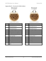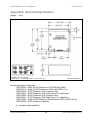
1
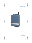
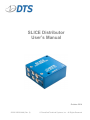
SLICE Distributor User’s Manual October 2014 13000-30030-MAN (Rev. 0) © Diversified Technical Systems, Inc. - All Rights Reserved SLICE Distributor User’s Manual October 2014 Table of Contents DTS Support ....................................................................................................................... 3 Introducing the SLICE Distributor .................................................................................... 4 SLICE Distributor Connector Panel .................................................................................. 4 LED Indicator ................................................................................................................... 5 On/Off Pushbutton Switch ................................................................................................ 5 SYS and AUX Connectors ............................................................................................... 5 Communication Features............................................................................................. 6 SLICE System Connectors .............................................................................................. 6 Basic Care and Handling ................................................................................................... 7 Shock Rating.................................................................................................................... 7 Mounting Considerations ............................................................................................. 7 Thermal Considerations ................................................................................................... 7 Power Management............................................................................................................ 8 Maximum Power Consumption ........................................................................................ 8 Maximum Input Power ..................................................................................................... 8 Maximum Output Power .................................................................................................. 8 Charging/Powering Attached Equipment ......................................................................... 8 Power Requirements of SLICE Equipment .................................................................. 9 Grounding ........................................................................................................................... 9 Troubleshooting Basics .................................................................................................... 9 Appendix A: Connector Information.............................................................................. 11 Appendix B: Mechanical Specifications........................................................................ 13 support.dtsweb.com ii 13000-30030-MAN (Rev. 0) SLICE Distributor User’s Manual October 2014 DTS Support SLICE systems are designed to be reliable and simple to operate. Should you need assistance, DTS has support engineers worldwide with extensive product knowledge and crash test experience to help via telephone, e-mail or on-site visits. The best way to contact a DTS support engineer is to submit a request through the DTS Help Center web portal (support.dtsweb.com). You must be registered (support.dtsweb.com/registration) to submit a request (https://support.dtsweb.com/hc/enus/requests/new). Registration also enables access to additional self-help resources and non-public support information. This manual supports the following products: 13000-30030: SLICE Distributor support.dtsweb.com 3 13000-30030-MAN (Rev. 0) SLICE Distributor User’s Manual October 2014 Introducing the SLICE Distributor The SLICE Distributor serves as a single interface supporting power, Ethernet communications and status signals for an extended SLICE system. It supports in excess of 200 channels via four SLICE MICRO/NANO chains (four stacks per chain), and is designed to integrate in-dummy and withstand high shock environments. Rated for 500 g dynamic testing environments. Supports >200 SLICE MICRO/NANO DAS channels via 4 SLICE system connectors. Supports an input range of 9-18 VDC (15 VDC nominal), 10 A maximum. Supports main and battery back-up power inputs. Supports Ethernet communications. Over- and undervoltage protection, overcurrent protection, power input polarity protection. LED indicator provides status information. Integral mounting holes. Ideal for embedded and in-dummy high channel-count applications. SLICE Distributor Connector Panel The ON switch, LED indicator and all connectors are accessible from the front panel. Instructions on how to properly connect cables can be found in the section on Troubleshooting Basics. Connector information and pin assignments can be found in Appendix A. Mechanical specifications are included in Appendix B. Please see your packing list for the hardware specifics (e.g., IP address) of your equipment. SLICE MICRO/NANO DAS connectors (1-4) - Functionally identical - Supports power, start, event, status and USB communications AUX connector - Status and control signals - Back-up power input Pushbutton Switch Status LED SYS connector - Main power input - Ethernet communications - Status and control signals SLICE Distributor Connector Panel support.dtsweb.com 4 13000-30030-MAN (Rev. 0) SLICE Distributor User’s Manual October 2014 LED Indicator There is one LED that provides status information. This LED is an indicator of SLICE Distributor status only; it does not indicate the status of any attached equipment. A thorough understanding of the LED states will facilitate an efficient approach to troubleshooting and a quick resolution to any problems. SLICE Distributor Status Unit off; no input power detected Unit off; input power detected (input range OK); output power is active Unit initializing Unit on (input range OK); all outputs active Input power is overvoltage –or– overcurrent condition is present (If unit is on, cycle power to reset) On/Off Pushbutton Switch A momentary pushbutton switch is used for on/off control. When the unit is on (LED is blue), all internal system electronics and output power are energized and the unit is fully functional. (This is the normal operating mode.) When the unit is off, the LED is either green (input power detected) or off (no input power). SYS and AUX Connectors The functions available via the SYS and AUX connectors are summarized below. Function Power on Event Recording status On status Start record (5 V) Start record (contact closure) Ethernet communications Main power input Back-up power input Whenever sufficient input power is connected to the SYS connector, all attached SLICE DAS containing an internal battery will charge. support.dtsweb.com 5 13000-30030-MAN (Rev. 0) SLICE Distributor User’s Manual October 2014 Communication Features The SLICE Distributor supports the industry-standard Ethernet 10/100BaseT/Tx communication method. Communication is enabled after the power-up sequence has completed. Please see your packing list for the hardware specifics (e.g., IP address) of your equipment. (If you need information on the specifics of your equipment, please submit a request through the DTS Help Center web portal (support.dtsweb.com) and include the serial number(s) of the equipment you are asking about.) SLICE System Connectors These 4 connectors are identical and support power, start, event, status and USB communication signals for the DAS. One SLICE connector supports up to 3 SLICE stacks, with a maximum of 8 SLICE Bridges per stack, in any combination of SLICE MICRO or NANO. SLICE MICRO Accel and ARS units can be used in place of a Bridge and the SLICE NANO Battery can be used with any SLICE NANO stack. = + + = 72 ch + (maximum) (Original Base MICRO and/or NANO; SLICE NANO Battery optional) = + + = 96 ch + (maximum) (MICRO and/or NANO Base+; SLICE NANO Battery optional) Maximum current for all 4 SLICE System connectors combined is 10 A with a maximum of 4 A per connector. Carefully calculate your expected maximum power consumption to ensure compliance with power limits. (Please see page 9 for information on power requirements.) support.dtsweb.com 6 13000-30030-MAN (Rev. 0) SLICE Distributor User’s Manual October 2014 Basic Care and Handling The SLICE Distributor is designed to operate reliably in dynamic testing environments. Though resistant to many environmental conditions, care should be taken not to subject the unit to harsh chemicals, submerge it in water, or drop it onto any hard surface. WARNING: Electronic equipment dropped from desk height onto a solid floor may experience as much as 10,000 g. Under these conditions, damage to the unit is likely. If you plan to store the unit, place it in a location with ambient temperatures below 30°C, low relative humidity, and free from dust and direct sunlight. When not in use or if shipping is required, we suggest that you always place the unit in the padded carrying case originally provided with your system. When transporting the unit, treat it as you might a laptop computer. The SLICE Distributor is not user-serviceable and should be returned to the factory for service or repair. Shock Rating The SLICE Distributor is rated for 500 g, 4 ms half-sine duration, in all axes. Mounting Considerations The unit should be securely bolted to the test article or dynamic testing device to provide the best shock protection. Mounting methods and hardware selection should be carefully calculated to withstand expected shock loading and facilitate proper grounding. Check bolt tightness periodically to ensure that the unit is securely fastened to the baseplate or testing platform. (See Appendix B for the unit’s mechanical specifications.) Thermal Considerations It is unlikely that the unit will overheat if common-sense measures are taken. In normal use, the SLICE Distributor is bolted to a structure with enough thermal mass to serve as a heat sink, keeping the temperature well within acceptable limits. However, when used continuously at the maximum output level, the unit may get very warm to the touch. Since the system draws the most power when armed, running the calibrations and arming as late as possible will minimize self-heating, particularly in embedded applications. Should you have any questions about using the SLICE Distributor in your environment, please contact DTS. support.dtsweb.com 7 13000-30030-MAN (Rev. 0) SLICE Distributor User’s Manual October 2014 Power Management The SLICE Distributor should be powered from a high-quality power source with output voltage and current ratings appropriate for the installation. It does not contain an internal power source, but has separate connectors to support main power and back-up power inputs. The SLICE Distributor contains power conditioning circuitry with a wide input range and well-regulated outputs. It will boost input voltages at the low end of the specified range in order to maintain a consistent output voltage. This conversion, however, will come at the expense of the supplied input current. A simple voltage measurement at the cable end that connects directly to the SLICE Distributor will verify whether the unit is receiving sufficient input voltage. Maximum Power Consumption The maximum power consumption is 180 W. Maximum Input Power The maximum input power is 15 VDC nominal (9-18 VDC range) at 10 A. Maximum Output Power The combined maximum output power available via the 4 SLICE system connectors is 120 W (12 V at 10 A). The maximum output power available per SLICE system connector is 12 V at 4 A. The maximum output current available via the AUX connector is 2.5 A (input VDC = output VDC). Charging/Powering Attached Equipment Whenever sufficient main input power is connected to the SLICE Distributor, it will simultaneously power and charge any attached SLICE DAS containing an internal battery. The length of time required to charge attached equipment depends primarily on the discharge state of the batteries. The SLICE Distributor does not need to be on in order to charge attached equipment. WARNING: Interconnecting SLICE equipment while signals/power are active/hot is not supported. The SLICE Distributor uses a common 12-conductor SLICE system chain connector that supports power, communication and control signals. If a port or cable is hot, it is possible that the locking clip or incorrect connector orientation might randomly short pins and damage the equipment. Application of power and other signals should occur after all cables have been connected to the SLICE Distributor. DTS strongly suggests following this procedure at all times to avoid potential damage to your equipment. support.dtsweb.com 8 13000-30030-MAN (Rev. 0) SLICE Distributor User’s Manual October 2014 Power Requirements of SLICE Equipment SLICE DAS use extensive power management to minimize power consumption. The lowest power demand condition is during charging when power is off. Current demand is at its maximum when the systems are fully armed and powering full sensor loads. Power Consumption (per item) Power Off (charging battery) Power On (armed + max load) SLICE NANO/MICRO - Base/Base+ - Bridge - Battery (NANO only) - Accel (MICRO only) - ARS (MICRO only) - IEPE (MICRO only) ----100 mA ------- 100 mA/70 mA 110 mA/75 mA* 100 mA 65 mA 75 mA 70 mA/85 mA* * Base+ For additional information, please see the SLICE User’s Manual. Grounding The SLICE Distributor has integrated mounting holes that will provide a simple method of grounding the entire data acquisition system when bolted to a properly-grounded test fixture. DTS recommends checking continuity between the SLICE Distributor and the test fixture to confirm resistance readings of <1 ohm. Troubleshooting Basics Begin troubleshooting by checking the operational state of the SLICE Distributor alone. DTS suggests always using the connection sequence below to avoid possible damage from hot swapping the cables. 1. With the unit off (and no DAS connected), connect the SLICE Distributor’s power source to the SYS connector. – If the status LED is green, then voltage input levels are within specifications and main output power is active. Proceed to step 2. – If the status LED is off, this can mean that the input voltage is too low or input polarity is reversed. You will need to correct this before proceeding. – If the status LED is red, this can mean: a) Input voltage is too high. You will need to correct this before proceeding. b) Overcurrent condition is present. This likely means the SLICE Distributor is not working properly. Contact DTS Support for assistance. 2. When the status LED is green, turn on the SLICE Distributor. 3. When the status LED is solid blue, the SLICE Distributor is on and fully functional (all internal system electronics and output power are energized). This is the normal operating mode. support.dtsweb.com 9 13000-30030-MAN (Rev. 0) SLICE Distributor User’s Manual October 2014 If the SLICE Distributor is operating normally, the next step is to add the DAS. DTS suggests always using the connection sequence below to avoid possible damage from hot swapping the cables. 1. With the unit off and power not connected, connect the SLICE DAS to the SLICE system connectors. 2. Connect the SLICE Distributor’s power source to the SYS connector. 3. When the status LED is green, turn on the SLICE Distributor. – When the status LED is solid blue (normal operating mode), then inspect the LED indicators on the SLICE DAS for system health. – If the status LED is red, this can mean input voltage is too high or overcurrent condition is present. You will need to correct this before proceeding. 4. Connect the Ethernet comm cable from the SYS connector to your PC. If at any time the status LED indicator shows an error or fault condition, you will need to correct this before proceeding. (The LED is an indicator of SLICE Distributor status only; it does not indicate the status of any attached equipment.) A fault signal generated by the SLICE Distributor or SLICE DAS is forwarded externally via the AUX and SYS connectors and will prevent you from arming your system. When the DAS is recording data, the status signal from the AUX and SYS connectors will be high; the status signal will be low for all other states where the DAS is on and connected to the SLICE Distributor. support.dtsweb.com 10 13000-30030-MAN (Rev. 0) SLICE Distributor User’s Manual October 2014 Appendix A: Connector Information AUX connector SYS connector (pin 12 plugged) (pin 8 plugged) 9 9 5 13 16 1 4 1 4 5 13 10 10 16 14 (looking into the connector) 14 (looking into the connector) Pin Function Pin Function 1 2 /PWR_ON (contact closure to ground) -Event, isolated, bi-directional, contact closure to pin 3 +Event, isolated, bi-directional, contact closure to pin 2 Recording status (high = recording) Reserved -VDC input from ext battery/Ground -VDC input from ext battery/Ground Reserved Start record input (apply 5 V with respect to ground) +VDC input from external battery Ground No connection Reserved +VDC input from external battery Reserved Start record input, contact closure to ground 1 2 /PWR_ON (contact closure to ground) -Event, isolated, bi-directional, contact closure to pin 3 +Event, isolated, bi-directional, contact closure to pin 2 Recording status (high = recording) ON status Ground Ground No connection Start record input (apply 5 V with respect to ground) 9-18 VDC in Ground Ethernet Tx+ Ethernet Rx+ 9-18 VDC in Ethernet TxEthernet Rx- 3 4 5 6 7 8 9 10 11 12 13 14 15 16 support.dtsweb.com 3 4 5 6 7 8 9 10 11 12 13 14 15 16 11 13000-30030-MAN (Rev. 0) SLICE Distributor User’s Manual October 2014 SLICE system connectors (1-4) 3 1 7 4 10 12 8 11 (looking into the connector) Pin 1 2 3 4 5 6 7 8 9 10 11 12 support.dtsweb.com Function /ON, bi-directional, contact closure input to ground /START, bi-directional, contact closure input to ground /EVENT, bi-directional, contact closure input to ground Status output (3 V = recording) 12 VDC out 12 VDC out Ground Ground USB_PWR USB_DP USB_DM Ground 12 13000-30030-MAN (Rev. 0) SLICE Distributor User’s Manual October 2014 Appendix B: Mechanical Specifications Weight: ~135 g Use M4* or 6-32** screws Units in inches (mm) Torque specs: * 19.8 in-lb (2.24 Nm); ** 9.6 in-lb (1.1 Nm) Accessories/support equipment: 13000-3010x: Cable, SLICE Distributor to SYSTEM port (DMD) 13000-30110: Cable, SLICE Distributor to DDX cable (SDX) (1 m) 13000-30440: SLICE Distributor AUX Connector Assy 13000-30441: SLICE Distributor AUX Cable Assy (5 m; pigtail term) 13000-30450: SLICE Distributor SYS Connector Assy 13000-30451: SLICE Distributor SYS Cable Assy (5 m; pigtail term) 13000-30660: Cable, SLICE Distributor, Ethernet comm (SYS to RJ45) (20 m) 13000-40050: SLICE Distributor Cable Kit (x = multiple lengths available) support.dtsweb.com 13 13000-30030-MAN (Rev. 0) SLICE Distributor User’s Manual October 2014 Revision History Date By 30 Oct 2014 EK support.dtsweb.com Description Initial release. (Rev 0) 14 13000-30030-MAN (Rev. 0)