1
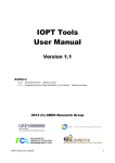
Documentation of the LinUDP Interface of the following Drives:
- E1250-IP-UC
- E1400-IP-QN
LinUDP Interface
User Manual
LinMot User Manual
LinMot User Manual
© 2012 NTI AG
This work is protected by copyright.
Under the copyright laws, this publication may not be reproduced or transmitted in any form, electronic or mechanical, including
photocopying, recording, microfilm, storing in an information retrieval system, not even for didactical use, or translating, in whole or in
part, without the prior written consent of NTI AG.
LinMot® is a registered trademark of NTI AG.
The information in this documentation reflects the stage of development at the time of press and is therefore without obligation.
NTI AG reserves itself the right to make changes at any time and without notice to reflect further technical advance or product
improvement.
Document version 1.1 / ka, August 2012
NTI AG / LinMot®
www.LinMot.com
Page 2/19
LinMot User Manual
1 Overview.........................................................................................................................4
2 Installation on Servo Drive............................................................................................4
3 Connecting LinUDP........................................................................................................4
3.1 Pin Assignment of the Connectors X17 - X18...........................................................4
4 LinUDP Telegram............................................................................................................5
4.1 DHCP Header...........................................................................................................5
4.2 IPv4 Header..............................................................................................................5
4.3 LinUDP Header.........................................................................................................5
4.4 LinUDP Data.............................................................................................................5
4.4.1 Request from the Master....................................................................................6
4.4.2 Response from the Drive...................................................................................7
5 LinUDP Parameters........................................................................................................7
6 LinUDP Modules.............................................................................................................8
6.1 Master to drive Modules............................................................................................8
6.2 Drive to master Modules...........................................................................................9
7 Real Time Config Module.............................................................................................10
8 Contact Addresses.......................................................................................................19
NTI AG / LinMot®
www.LinMot.com
Page 3/19
LinMot User Manual
Table of Content
LinMot User Manual
The LinUDP protocol is an easy way for communication with a LinMot servo drive
over Ethernet. There are no checks done to make sure if the messages have
reached their destination and if they are correctly received. When communicating
via LinUDP, the drive has no active function, it only responds to requests with the
appropriate answers.
2 Installation on Servo Drive
For installing the LinUDP firmware on the servo drive, start the LinMot- Talk
software and press the install firmware button
. Choose the file
“Firmware_Buildxxxxxxxx.sct” and press “Open”. The wizard will guide you through
the installation. When asking for the interface software choose “LinUDP”:
Press ok and follow the rest of the wizard.
3 Connecting LinUDP
3.1 Pin Assignment of the Connectors X17 - X18
The Ethernet/IP connector is a standard RJ45 female connector with a pin
assignment as defined by EIA/TIA T568B:
X17 – X18
RealTime Ethernet Connector
Pin
RJ-45
NTI AG / LinMot®
Wire color code
Assignment 100BASE-TX
1
WHT/ORG
Rx+
2
ORG
Rx-
3
WHT/GRN
Tx+
4
BLU
-
5
WHT/BLU
-
6
GRN
Tx-
7
WHT/BRN
-
8
BRN
-
case
-
-
Use standard patch cables (twisted pair, S/UTP, AWG26) for
wiring. This type of cable is usually referred to as a “Cat5eCable”.
www.LinMot.com
Page 4/19
LinMot User Manual
1 Overview
LinMot User Manual
4 LinUDP Telegram
Name
Size [Byte]
DHCP Header
14
IPv4 Header
20
LinUDP Header
8
LinUDP Data
message dependent
LinMot User Manual
In LinUDP there are two telegrams used, one for the request from the master and
the other one for the response from the drive. These two telegrams have the
following layout:
4.1 DHCP Header
The DHCP Header looks like in the following table.
0. Byte
1. Byte
2. Byte
+0
3. Byte
4. Byte
5. Byte
6. Byte
7. Byte
Destination MAC ID
+8
Source MAC ID
Protocol Typ (0x0800)
4.2 IPv4 Header
The IPv4 header is described in the rfc0791 in chapter 3.1. Rfc0791 could be found
on www.ietf.org/rfc/rfc0791.txt. The sections options and padding are not used.
4.3 LinUDP Header
The LinUDP header consists of four parts. They are showing ind the following table.
Name
Size [Byte]
Source Port
2
Destination Port
2
Length of UDP Telegram
2
UDP Checksum
2
The LinUDP ports are fix assigned. For the Master it is port 41136 and for the drive
it is port 49360. In Hex-Code they are A0B0 and C0D0.
4.4 LinUDP Data
In LinUDP data are the data which we want to transfer. The construction of this data
NTI AG / LinMot®
www.LinMot.com
Page 5/19
LinMot User Manual
part always is the same. The only difference are the source and destination, they
are switched.
The first 32 bits of the LinUDP data define the request and the following 32 bits
define the format of the response. The following tables show how the request
definition and the response definition look like.
Request definition
Bit
Name
Data size [Byte]
0
Control Word
2
1
MC Interface
32
2
Realtime Configuration
8
3 – 31
Reserved for future expansions
Response definition
Bit
Name
Data size [Byte]
0
Status Word
2
1
State Var
2
2
Actual Position
4
3
Demand Position
4
4
Current
2
5
Warn Word
2
6
Error Code
2
7
Monitoring Channel
16
8 – 31
Reserved for future expansions
Each of the definition bits shows if the corresponding parameter is part of the
communication. The order of the requested data parts is the same as the definition
bits. When a definition bit is not set, the data part would not be transferred. When
all bits of the request definition are set, then the LinUDP data looks like it is shown
in the following table. Each field represents one byte.
NTI AG / LinMot®
www.LinMot.com
Page 6/19
LinMot User Manual
4.4.1 Request from the Master
LinMot User Manual
0. Byte
+0
1. Byte
2. Byte
3. Byte
4. Byte
Request Definition
+8
5. Byte
6. Byte
7. Byte
Response Definition
Control Word
+24
LinMot User Manual
+16
MC Interface
+32
+40
Realtime Configuration
+48
4.4.2 Response from the Drive
The LinUDP data part of a response from a drive has the same construction like the
data part of a request. The order of the response data part is the same as the
response definition bits. The only exception is the last part of the response data part
with the realtime configuration data. When all bits in the response definition are set
then the response data part looks like in the following table.
0. Byte
+0
1. Byte
2. Byte
3. Byte
4. Byte
Request Definition
+8
Status Word
+16
State Var
Error Code
+32
6. Byte
7. Byte
Response Definition
Actual Position
Demand Position
+24
5. Byte
Current
Warn Word
Monitoring Channel
Realtime Configuration
+40
5 LinUDP Parameters
The LinUDP servo drives have an additional parameter tree branch, which can be
configured with the distributed LinMot-Talk software. With these parameters, the
LinUDP behaviour can be defined. The LinMot-Talk software can be downloaded
from http://www.linmot.com under the section download, software & manuals.
The additional parameter tree branch is called “LinUDP Intf”. In this branch are the
following Parameters.
•
Dis-/Enable, with this Parameter the interface could be turned off and on.
•
Ethernet Configuration is the part where the connection type could be
chosen.
NTI AG / LinMot®
www.LinMot.com
Page 7/19
LinMot User Manual
•
Monitoring Channels defined 4 UPID. The values of this UPID are in the
response data part when the monitoring channel bit is set active.
Channel 1 UPID
Source UPID for Monitoring Channel 1
Parameter UPID = 20A8
Channel 2 UPID
Source UPID for Monitoring Channel 2
Parameter UPID = 20A9
Channel 3 UPID
Source UPID for Monitoring Channel 3
Parameter UPID = 20AA
Channel 4 UPID
Source UPID for Monitoring Channel 4
Parameter UPID = 20AB
•
•
Master Configuration is for the communication safety. With the radio
buttons under single master there can chosen three possibilities.
•
No Filter means the drive does no control. This option is choose per
default.
•
Single Master means the drive takes the IP Address from the sender
of the first LinUDP telegram, which it receives and after that it only
responses to telegrams with this address.
•
Single Master with fix IP: In the parameters called Master IP Address
define a IP Address and the drive only responses to telegrams with
this fix address.
Master IP Address the fix IP address is defined in this parameters.
6 LinUDP Modules
In LinUDP there are three modules implemented for the master to drive
communication and eight modules for the drive to master communication.
6.1 Master to drive Modules
Control Word
With the control word the main state machine of the drive can be accessed. Please
refer to “User Manual Motion Control Software” for the control word.
MC Cmd Interface
This maps the MC command interface of the drive. Please refer to the
documentation of the MC software.
Real Time Configuration
The real time configuration module allows accessing to parameters, variables,
curves, error log and command table. Also restart, start and stop of the drive can be
initiated. Of course the parameter channel module works independently from the
MC command interface. For this reason, changing a parameter and sending a
motion command can be done in parallel. The real time configuration has influence
on both telegram directions. For details see chapter 6 Real Time Config.
NTI AG / LinMot®
www.LinMot.com
Page 8/19
LinMot User Manual
Monitoring Channels
LinMot User Manual
6.2 Drive to master Modules
Status Word
The status word consists of 16 bits. Please refer to “User Manual Motion Control
Software” for watch about the meaning of each bit the status word.
The State Var consists of MainState and SubState. Please refer to the table “State
Var” on chapter 3 of the “User Manual Motion Control Software”. The State Var has
all relevant flags and information for clean handshaking within one word and can
therefore replace the modules “Get MC Header Echo” and “Get Error Code”.
Actual Position
Returns the actual position of the motor. (32 Bit integer value, resolution 0.1 µm)
Demand Position
Returns the demand position of the motor. (32 Bit integer value, resolution 0.1 µm)
Current
Returns the set current of the motor. (32 Bit integer value, resolution 1 mA)
Warn Word
Returns the warn word. Please refer to “User Manual Motion Control Software”.
Error Code
Returns the error code. Please refer to “User Manual Motion Control Software” for
the Error Codes of the MC software.
Monitoring Channel
Transmits cyclically the value of the variable, which is defined by the monitoring
channel Parameter (see chapter 3)
NTI AG / LinMot®
www.LinMot.com
Page 9/19
LinMot User Manual
State Var
LinMot User Manual
7 Real Time Config Module
Word number
DO
DI
1.
Parameter Channel Control
Parameter Channel Status
2.
3.
4.
Argument (meaning depends on Cmd
Argument (meaning depends on Cmd
ID)
ID)
Argument (meaning depends on Cmd
Argument (meaning depends on Cmd
ID)
ID)
Argument (meaning depends on Cmd
Argument (meaning depends on Cmd
ID)
ID)
Real Time Config Control
Parameter Command ID to be executed
15
14
13
12
11
10
9
Reserved
8
7
6
Command Count
5
4
3
2
1
0
The Parameter Channel Control is split in two parts:
• Parameter Command ID to be executed (bits 8-15), see table Command ID
• Command Count (bits 0-3)
Real Time Config Status
Parameter Status
15
14
13
Reserved
12
11
10
9
8
7
6
Command Count
Response
5
4
3
2
1
0
The Parameter Channel Status is split in two parts:
• Parameter Status (bits 8-15), see table Parameter Status
• Command Count Response (bits 0-3)
Command Count
A new command is only evaluated, if the value of the command count changes. In
the easiest way bit 0 could be toggled.
NTI AG / LinMot®
www.LinMot.com
Page 10/19
LinMot User Manual
The structure of the real time config is shown in the following table. DO stands for
data output and DI for data input. The point of view for the definition of DO and DI is
the Master.
LinMot User Manual
Parameter Command ID
This selects the command.
Command ID
Description
00h
No Operation
LinMot User Manual
Possible Commands are:
Parameter Access
10h
Read ROM Value of Parameter by UPID
11h
Read RAM Value of Parameter by UPID
12h
Write ROM Value of Parameter by UPID
13h
Write ROM Value of Parameter by UPID
14h
Write RAM and ROM Value of Parameter by UPID
15h
Get minimal Value of Parameter by UPID
16h
Get maximal Value of Parameter by UPID
17h
Get default Value of Parameter by UPID
Parameter (UPID) List
20h
Start Getting UPID List
21h
Get next UPID List item
22h
Start Getting Modified UPID List
23h
Get next Modified UPID List item
Stop / Start / Default
30h
Restart Drive
31h
Set parameter ROM values to default (OS SW)
32h
Set parameter ROM values to default (MC SW)
33h
Set parameter ROM values to default (Interface SW)
34h
Set parameter ROM values to default (Application SW)
35h
Stop MC and Application Software (for Flash access)
36h
Start MC and Application Software
NTI AG / LinMot®
www.LinMot.com
Page 11/19
LinMot User Manual
40h
Save all Curves from RAM to Flash
41h
Delete all Curves (RAM)
50h
Start Adding Curve (RAM)
51h
Add Curve Info Block (RAM)
52h
Add Curve Data (RAM)
53h
Start Modifying Curve (RAM)
54h
Modify Curve Info Block (RAM)
55h
Modify Curve Data (RAM)
60h
Start Getting Curve (RAM)
61h
Get Curve Info Block (RAM)
62h
Get Curve Data (RAM)
LinMot User Manual
Curve Service
Error Log
70h
Get Error Log Entry Counter
71h
Get Error Log Entry Error Code
72h
Get Error Log Entry Time low
73h
Get Error Log Entry Time high
74h
Get Error Code Text Stringlet
Command Table
80h
Command Table: Save to Flash
81h
Command Table: Delete All Entries (RAM)
82h
Command Table: Delete Entry
83h
Command Table: Write Entry
84h
Command Table: Write Entry Data
85h
Command Table: Get Entry
86h
Command Table: Get Entry Data
87h
Get Presence List of Entries 0..31 from RAM
88h
Get Presence List of Entries 32..63 from RAM
89h
Get Presence List of Entries 64..95 from RAM
NTI AG / LinMot®
www.LinMot.com
Page 12/19
LinMot User Manual
Get Presence List of Entries 96..127 from RAM
8Bh
Get Presence List of Entries 128..159 from RAM
8Ch
Get Presence List of Entries 160..191 from RAM
8Dh
Get Presence List of Entries 192..223 from RAM
8Eh
Get Presence List of Entries 224..255 from RAM
Parameter Status
Description
00h
OK, done
02h
Command Running / Busy
04h
Block not finished (Curve Service)
05h
Busy
C0h
UPID Error
C1h
Parameter Type Error
C2h
Range Error
C3h
Address Usage Error
C5h
Error: Command 21h “Get next UPID List item” was executed without prior
execution of “Start Getting UPID List”
C6h
End of UPID List reached (no next UPID List item found)
D0h
Odd Address
D1h
Size Error (Curve Service)
D4h
Curve already defined / Curve not present (Curve Service)
NTI AG / LinMot®
www.LinMot.com
LinMot User Manual
8Ah
Page 13/19
LinMot User Manual
Word
DO
DI
1.
Parameter Channel Control
Parameter Channel Status
2.
Parameter UPID
Parameter UPID
3.
Parameter Value Low
Parameter Value Low
4.
Parameter Value High
Parameter Value High
Overview Curve access:
Word
DO
DI
1.
Parameter Channel Control
Parameter Channel Status
2.
Curve Number
Curve Number
3.
Data Value Low / Info Block size
Data Value Low / Info Block size
4.
Data Value High / Data Block size
Data Value High / Info Block size
Start getting UPID List:
Word
DO
DI
1.
Parameter Channel Control
Parameter Channel Status
2.
Start UPID (search from this UPID)
-
3.
-
-
4.
-
-
Get next UPID List item:
Word
DO
DI
1.
Parameter Channel Control
Parameter Channel Status
2.
-
UPID found
3.
-
Address Usage
4.
-
-
NTI AG / LinMot®
www.LinMot.com
Page 14/19
LinMot User Manual
Overview Parameter access
LinMot User Manual
14
13
12
11
10
9
8
7
6
5
4
3
1
Start getting Modified UPID List (Command ID 22h):
Word
DO
DI
1.
Parameter Channel Control
Parameter Channel Status
2.
Start UPID (search from this UPID)
-
3.
-
-
4.
-
-
Get next Modified UPID List item (Command ID 23h):
Word
DO
DI
1.
Parameter Channel Control
Parameter Channel Status
2.
-
UPID found
3.
-
Data Value Low
4.
-
Data Value High
Get Error Log Entry Counter (Command ID 70h):
Word
DO
DI
1.
Parameter Channel Control
Parameter Channel Status
2.
-
-
3.
-
Number of Logged Errors
4.
-
Number of Occurred Errors
NTI AG / LinMot®
www.LinMot.com
RAM Read
RAM Write
ROM Read
2
Page 15/19
0
LinMot User Manual
15
ROM Write
calculation Not used for Hash
Life Parameter
Address Usage:
LinMot User Manual
Get Error Log Entry Error Code (Command ID 71h):
DO
DI
1.
Parameter Channel Control
Parameter Channel Status
2.
Entry Number (0..20)
Entry Number
3.
-
Logged Error Code
4.
-
-
LinMot User Manual
Word
Get Error Log Entry Time Low (Command ID 72h):
Word
DO
DI
1.
Parameter Channel Control
Parameter Channel Status
2.
Entry Number (0..20)
Entry Number
3.
-
Entry Time Low Word
4.
-
Entry Time Mid Low Word
Get Error Log Entry Time High (Command ID 73h):
Word
DO
DI
1.
Parameter Channel Control
Parameter Channel Status
2.
Entry Number (0..20)
Entry Number
3.
-
Entry Time Mid High Word
4.
-
Entry Time High Word
The Error Log Entry Time consists of 32 Bit hours (Time High) and 32 Bits ms (Time
Low).
Get Error Code Text Stringlet (Command ID 74h):
Word
DO
DI
1.
Parameter Channel Control
Parameter Channel Status
2.
Error Code
Error code
3.
Stringlet Number (0..7)
Stringlet Byte 0 and 1
4.
-
Stringlet Byte 2 and 3
NTI AG / LinMot®
www.LinMot.com
Page 16/19
LinMot User Manual
Word
DO
DI
1.
Parameter Channel Control
Parameter Channel Status
2.
-
-
3.
-
-
4.
-
-
For this command, the MC software must be stopped (with command “35h: Stop MC and
Application Software”). The LinUDP Interface will stay active while the MC software is
stopped.
Command Table: Delete All Entries (RAM) (Command ID 81h):
Word
DO
DI
1.
Parameter Channel Control
Parameter Channel Status
2.
-
-
3.
-
-
4.
-
-
Command Table: Delete Entry (Command ID 82h):
Word
DO
DI
1.
Parameter Channel Control
Parameter Channel Status
2.
Entry Number
Entry Number
3.
-
-
4.
-
-
Command Table: Write Entry (Command ID 83h):
Word
DO
DI
1.
Parameter Channel Control
Parameter Channel Status
2.
Entry Number
Entry Number
3.
Block Size (even number of bytes)
Block Size
4.
-
-
NTI AG / LinMot®
www.LinMot.com
Page 17/19
LinMot User Manual
Command Table: Save to Flash (Command ID 75h):
LinMot User Manual
Word
DO
DI
1.
Parameter Channel Control
Parameter Channel Status
2.
Entry Number
Entry Number
3.
Data
Data
4.
Data
Data
Command Table: Get Entry (Command ID 85h):
Word
DO
DI
1.
Parameter Channel Control
Parameter Channel Status
2.
Entry Number
Entry Number
3.
-
Block Size
4.
-
-
Command Table: Get Entry Data (Command ID 86h):
Word
DO
DI
1.
Parameter Channel Control
Parameter Channel Status
2.
Entry Number
Entry Number
3.
-
Data
4.
-
Data
Command Table: Get Entry List (0..7) (Command IDs 87h .. 8Eh):
Word
DO
DI
1.
Parameter Channel Control
Parameter Channel Status
2.
-
Offset in bytes
3.
-
Bit field (Bit set = undefined / Bit
cleared = used)
4.
-
Bit field (Bit set = undefined / Bit
cleared = used)
NTI AG / LinMot®
www.LinMot.com
Page 18/19
LinMot User Manual
Command Table: Write Entry Data (Command ID 84h):
LinMot User Manual
SWITZERLAND
USA
NTI AG
Haerdlistr. 15
CH-8957 Spreitenbach
Sales and Administration:
+41-(0)56-419 91 91
[email protected]
Tech. Support:
+41-(0)56-544 71 00
[email protected]
Tech. Support (Skype) :
skype:support.linmot
Fax:
Web:
+41-(0)56-419 91 92
http://www.linmot.com/
LinMot, Inc.
5750 Townline Road
Elkhorn, WI 53121
Sales and Administration:
877-546-3270
262-743-2555
Tech. Support:
877-804-0718
262-743-1284
Fax:
800-463-8708
262-723-6688
E-Mail:
Web:
[email protected]
http://www.linmot-usa.com/
Please visit http://www.linmot.com/ to find the distributor closest to you.
Smart solutions are…
NTI AG / LinMot®
www.LinMot.com
Page 19/19
LinMot User Manual
8 Contact Addresses