1
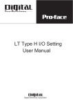
Data, Acquisition and Control econ9 PLC i4-100 econ9 PLC i4-100 Variants Part.-No. econ9 PLC i4-100 10910401 Accessories Part.-No. Patch Cable, Length 2 m 3030166 CrossOver Cable, Length 2 m 3030167 Backup Battery 2080205 2 GB Micro-SD-Card (max. 32 GB) 6010146 St 2x10pol FMCD 1,5 RM3,5 (terminal clamp for I/O) 2050217 Extensions Part.-No. in planning Functions Overview CODESYS Firmware SD-Card USB Ethernet FTP-Server X remanent RAM RS485 X Webvisu CAN / CANopen Fast-Counter-Inputs Encoder-Inputs PTO-Outputs X PWM-Outputs User Manual econ9 X Interrupt-Inputs Technical Data: • 1 CAN-Interface • 1 RS485 • 1 Ethernet-Interface (10/100 Base-T) • 1 USB2.0 Host • 64 MB DDR2 RAM • 256 MB Nand-Flash • Backup Battery, Typ CR2032 • Real-time clock • 2 MB SRAM, battery buffered • 1 Slot for Micro-SD-Card (microSDHC, max 32 GB) • Power supply: 24 V / ≤ 1 A DC • Housing Protection: IP20 • Mounting: DIN Rail DIN EN 60715, 35mm • Dimension (B x H x T): 53.2 x 110 x 100 mm • Operating Temperature: 5 ... + 55 °C • Weight: aprox. 0.2 kg • Programming Software: CODESYS V3 econ9 V121 Analog I/O The econ9 PLC i4-100 base controller is also fitted with multiple communication interfaces for easy networking and remote expansion, data can be stored on the optional μSD card permanently. Dig I/O CODESYS Firmware Description: The base controller econ9 PLC i4-100 combines a large number of functions. This functions can be extended by the modular structure of the overall system. The basic version includes multifunctional interfaces, which allow a high flexibility for optimal adaptation to the requirements. X X X X X Multifunctional In- / Outputs alternatively usable see combination matrix Page 6 • 8 Inputchannels, alternatively usable as 8 digital Inputs 24V 7mA, non isolated, high active 2 Interruptports 2 Incrementalencoderinputs 24V, max. 100 kHz 2 Fast Counter 24V, max. 100 kHz 4 analog Inputs, non isolated 0 ... +10 V, 12 Bit • 8 In- / Outputchannels, alternatively usable as 8 digital Inputs 24V 7mA, non isolated, high active 8 digital Outputs 24V 0.5 A, non isolated 2 digital Outputs, PWM/PTO, max. 100 kHz 2 analog Outputs, non isolated 0 ... +10 V, 12 Bit epis 10910401e Rev.: 03 •• 1 •• Data, Acquisition and Control econ9 PLC i4-100 CAN according to ISO/DIS 11898, isolated PIN assignment CAN-Interface Pin CAN 1/2 nc Number of Channels 1 1 Output Differential Voltage min. + 1.5 V, max. + 3 V 2 CAN_L 3 CAN_GND 4 --- 5 --- Input Differential Voltage recessive dominant min - 1 V, max. + 0.4 V min. + 1 V, max. + 5 V Input Offset Voltage (versus CAN-GND) max. +/- 6 V Input Differential Resistance min. 20 kΩ, max.100 kΩ Transmission Rate up to 15 m Cable Length up to 50 m Cable Length up to 150 m Cable Length up to 350 m Cable Length max. 1 MBit max. 500 kBit max. 250 kBit max. 125 kBit Number of Subscribers max. 64 Connecting Cable up to 100 m Cable Length up to 350 m Cable Length shielded, twisted 0.25 mm² 0.5 mm² Recommended Cable Fixed Installation Flexible Installation UNITRONIC® BUS CAN UNITRONIC® BUS FD P CAN 6 --- 7 CAN_H 8 --- 9 --- Twisted Pair NOTE: Termination of the CAN bus via a 120 Ω resistor between CAN_L (pin 2) and CAN_H (Pin 7) must be installed in the Sub-D socket of the CAN connection cable. Ethernet, isolated PIN-Belegung Ethernet-Schnittstelle Pin Ethernet Number of Channels 1, Twisted Pair (10/100BASE-T) 1 TX+ Transmission according to IEEE/ANSI 802.3, ISO 8802-3, IEEE802.3u 2 TX- Transmission Rate 10/100 Mbit/s Cable Length max. 100 m Cable shielded Impedance 100 Ω Plug RJ45 (Western Plug) LED – Status Display Yellow Green Active Link User Manual econ9 epis 10910401e Rev.: 03 3 RX+ 4 GND 5 GND 6 RX- 7 GND 8 GND •• 2 •• Data, Acquisition and Control econ9 PLC i4-100 RS485, non isolated PIN assignment R485-Interface Pin RS485 Number of Channels 1 1 nc Output Differential Voltage min. +/- 1.5 V max. +/- 5 V 2 --- Input Differential Voltage min. +/- 0.5 V max. +/- 5 V 3 --- 4 Data - (B) Input Offset Voltage (versus GND) max. - 6 V/+ 6 V 5 Termination - 6 GND Output Drive Current Udiff = +/- 1.5 V) max. +/- 55 mA Transmission Rate 1200 ... 115200 Bd Connecting Cable up to 0.14 mm² up to 0.25 mm² shielded, min. 0.14 mm² max. 300 m max. 600 m Termination by bridging Pin 4 and 5 and Pin 8 and 9, see note 7 --- 8 Data + (A) 9 Termination + NOTE: The termination of the RS485 interface has to be done on the both endpoints of the bus by bridging the pins 4 and 5 (Data -), and the pins 8 and 9 (Data +), in the Sub-D socket of the RS485 connection cable! USB 2.0 PIN assignment USB-Interface Pin USB 1 x Host (fullspeed) 1 + 5V USB 2.0 USB 2.0 compatible, connector Typ A 2 Data - 3 Data + Cable Length max. 5 m 4 GND Output Current max. 0.5 A Number of Channels User Manual econ9 epis 10910401e Rev.: 03 •• 3 •• Data, Acquisition and Control econ9 PLC i4-100 Power Supply Logic supply Rated Value Permissible Range PIN assignment Power Supply 24 V DC +20 % / -15% plus AC component with peak value of 5% of nominal voltage => 30 ... 19.2 V Actuator supply Rated Value Permissible Range 24 V 30...19.2 V Sensor supply Rated Value Permissible Range 24 V 30..19.2 V Current Consumption from 24 V ≤ 1 A for base unit Pin Supply 1 + 24 V 2 3 0V CPU, ARM cortex M4 Processor, memory Environmental conditions according to EN 61131-2 Clock Rate 120 MHz Nand-Flash 256 MB RAM 64 MB Temperature Operating Storage 5 ... + 55 °C - 25 ... + 70 °C SRAM 2 MB, battery buffered Humidity 10 ... 95 % non-condensing µSD-Karte max. 32 GB Oscillations 5...8.4 Hz, const.Ampl. 1.75 mm 8.4...150 Hz, Acceleration. 0.5g Shock occasional peak values up to 15 g over 11 ms half sine wave Elevation Operating Storage User Manual econ9 epis 10910401e Rev.: 03 up to 2000 m 0 … 3000 m •• 4 •• Data, Acquisition and Control econ9 PLC i4-100 Real-time clock Accuracy at 25° C at -10 ... +70° C Backup battery, Lithium - Cell, pluggable ≤ +/- 1 s / Day ≤ + 1 s ... - 11 s / Day Battery Type Li 3V / 220mAh CR2032 Backup Time at 20 °C nom. 5 Years Recommendation Battery Change after 2 Years Battery Change see User Manual NOTE: To avoid data loss while performing battery change, turn the device on for least 10 minutes prior to change over. Mechanical Data Electromag. compatibility according to EU Directive 2004/108/EG: Housing plastic module housing Dimensions (B x H x T) 53.2 x 110 x 100 mm Mounting Method DIN RAIL 35 mm according DIN EN 60715 Compliance according DIN 40050 / 7.80 Housing IP 20 Resistive according to DIN 42115 Alcohol, diluted acid and Alkaline, household cleaner Weight aprox. 0.2 kg Immunity for industrial environments in accordance with EN 61131-2 / EN 61000-6-2 Electrostatic discharge Contact Air EN 61000-4-2 min. ± 4 kV min. ± 8 kV Electromag. RF field ampl.mod. 80 MHz - 1 GHz 1.4 GHz - 2 GHz 2.0 GHz – 2.7 GHz EN 61000-4-3 10 V/m 80% AM (1 kHz) 3 V/m 80% AM (1 kHz) 1 V/m 80% AM (1 kHz) Fast transients DC network inputs / outputs Signal connections EN 61000-4-4 ± 2 kV ± 1 kV Surge unbalanced and balanced DC power inputs EN 61000-4-5 ± 0.5 kV, measured at the AC input of the used AC / DC converter High-frequency asymmetrical 0.15 - 80 MHz EN 61000-4-6 10 V, 80% AM (1 kHz) Emission standard for industrial areas according to EN 61131-2 / EN 61000-6-4 Radio interference 30 MHz - 1 GHz IEC/CISPR 16-2-3 40 / 47 dB (µVm) NOTE: To keep the rules of EMC/CE, a correct and entire construction, according to User Manual, is neccessary. The manufacturer assembling the system / machine, in which the controller is integrated, is responsible for the electromagnetic compatibility. In order to improve the quality we reserve the rights to change the product. User Manual econ9 epis 10910401e Rev.: 03 •• 5 •• Data, Acquisition and Control econ9 PLC i4-100 Multifunctionale In- /Outputs Top Pin 10: GND Pin 20: GND Pin 1: ext. + 24 VDC Bottom Pin 11: sensor power supply 24 VDC Caution: Reverse voltage on sensor power supply may damage the device!! Do not bridge Pin1 with Pin11! combination matrix In- / Outputchannels econ9 PLC i4-100 Pin/ J1 dig. Input dig. Output analog Input 0...+10V; 12 Bit analog Output 0...+10V; 12 Bit Interruptinput PWM-Output function blocks: (FB1; FB2) PTO-Output function blocks: (FB1; FB2) EncoderInput function blocks: (FB1; FB2) 2 I0 Q0 PWM0-FB1 3 I1 Q1 PWM1-FB1 4 I2 Q2 PWM2-FB2 5 I3 Q3 PWM3-FB2 6 I4 Q4 7 I5 Q5 8 I6 Q6 AO0 9 I7 Q7 AO1 12 I8 INT0 13 I9 INT1 14 I10 CH0A-FB1 15 I11 CH0B-FB1 16 I12 AI0 CH0Idx-FB1 17 I13 AI1 CH1A-FB2 18 I14 AI2 CH1B-FB2 19 I15 AI3 CH1Idx-FB2 Fast-CounterInput function blocks: (FB1; FB2) PTO0-FB1 LED Bottom PTO1-FB2 Cnt0-FB1 Cnt1-FB2 Top Note: PWM- / PTO-Outputs, Encoderinputs and Fast Counter-Inputs are grouped into functional blocks FB1 and FB2. There is only 1 functionality per function block possible according to pin assignment. PWM0 und PWM2 may be used alone. PWM1 may be used only in combination with PWM0. PWM2 may be used only in combination with PWM3. User Manual econ9 epis 10910401e Rev.: 03 •• 6 •• Data, Acquisition and Control econ9 PLC i4-100 Digital Inputs / Special Function Inputs, non-isolated Number of Channels Interruptports Incremental Encoder Inputs Timer- / Counter-Inputs Analog Inputs Supply Voltage Rated Value Permissible Range Input Current at Nominal Voltage (24 V) Block Diagram of digital Inputs 8, usable as 2 2 2 4 (see below) Pin/J1 Input / ENC / IN 11 +24 V Sensor Power Supply (Output) 12 I8 / INT0 13 I9 / INT1 14 24 V - 30 ... + 30 V I10 / CH0A-FB1 / Cnt0-FB1 15 I11 / CH0B-FB1 6.3 mA 16 I12 / CH0Idx-FB1 17 I13 / CH1A-FB2 / Cnt1-FB2 Input frequency at duty cycle 0.5 ≤ 100 kHz Delay Time Standard Inputs tLOW - HIGH tHIGH - LOW 2 µs 2 µs Input Voltage LOW - Level HIGH - Level ≤5V ≥ 15 V Input Current LOW - Level HIGH - Level ≤ 1.5 mA ≥ 3 mA Input Impedance 3.8 kΩ Sensor Suppply (Output) 24 V DC, max. 200 mA 18 I14 / CH1B-FB2 19 I15 / CH1Idx-FB2 20 GND when using as Incremental encoder Inputs Input signals 2-Phases-Rectangle moved about 90°, 1 Zero Impulse Signal Evaluation quadruple Analog Inputs, non-isolated Block Diagram of analog Inputs Number of Channels 4 Voltage Range 0 .. +10 V AD-Change Principle Resolution Conversion Time limiting frequency ADC successive approximation 12 Bit 7 µs 935 Hz max. Input Area Voltage 0 .. +15 V Input Impedance Voltage Range 90.8 kΩ Offset Error (0-Point) ≤ + 30 mV Gain Error +/- 1% Connection Cable length shielded max. 10 m User Manual econ9 epis 10910401e Rev.: 03 Pin/J1 AIN 11 +24 V Sensor Power Supply (Output) 16 AI0 17 AI1 18 AI2 19 AI3 20 GND •• 7 •• Data, Acquisition and Control econ9 PLC i4-100 Digital In- / Outputs / Special Function Inputs, non-isolated Block Diagram of digital Inputs Pin/J1 Input Number of Channels 8 1 ext. + 24 VDC uses as digital Inputs 8 2 I0 Input Voltage Permissible Range 24 V - 30 ... + 30 V 3 I1 4 I2 5 I3 6 I4 7 I5 8 I6 9 I7 10 GND Input Current HIGH – Level 6.4 mA Delay Time tLOW – HIGH tHIGH - LOW 1.5 ms 1.9 ms Threshold ULOW – HIGH UHIGH - LOW ≤5V ≥ 15 V Input Impedance 3.8 kΩ used as digital Outputs see page 9 Caution: Reserve current at the outputs may damage the output stage! User Manual econ9 epis 10910401e Rev.: 03 •• 8 •• Data, Acquisition and Control econ9 PLC i4-100 Block Diagram of digital Outputs 0.5 A or of PWM/PTO Outputs Digital In- / Outputs / Special Function Inputs, non-isolated Pin/J1 Output 1 ext. + 24 VDC Number of Channels 8 used as Digital-Eingänge see page 8 used as digital Outputs 4 2 Load Voltage Vin Nominal Value Permissible Range Q0 / PWM0-FB1 / PTO0-FB1 24 V 18 ... 30 V 3 Q1/ PWM1-FB1 4 Output Voltage HIGH – Level LOW – Level min. Vin – 0.39 V max. 2 µA x RLast Q2 / PWM2-FB2 / PTO1-FB2 Short Circuit Protected yes, thermal Overload Protection 5 Q3 / PWM3-FB2 Output Current 0.5 A DC Parallel switching of Outputs no Utilization factor 100% used as PWM/PTO Output 2 Output Current 0.5 A DC Short Circuit Protected yes, thermal Overload Protection Switching Frequency standard Output resistive load inductive load 100 kHz 100 kHz Simultaneous Factor 100% 6 7 8 9 10 GND Note: PWM- / PTO-Outputs, Encoderinputs and Fast Counter-Inputs are grouped into functional blocks FB1 and FB2. There is only 1 functionality per function block possible according to pin assignment. PWM0 und PWM2 may be used alone. PWM1 may be used only in combination with PWM0. PWM2 may be used only in combination with PWM3. Digital In- / Outputs / Special Function Inputs, non-isolated Block Diagram of digital Outputs 0.5 A Pin/J1 Output ext. + 24 VDC Number of Channels 8 1 used as Digital-Eingänge see page 8 2 used as digital Outputs 4 3 Load Voltage Vin Nominal Value Permissible Range 24 V 18 ... 30 V Output Voltage HIGH – Level LOW – Level min. Vin – 0.07 V max. 5 µA x RLast Output Current 0.5 A DC Parallel switching of Outputs possible, max. 4 Outputs Short Circuit Protected yes, thermal Overload Protection Switching Frequency standard Output resistive load inductive load 100 Hz 2 Hz (depends on inductivity) Lamp load max. 6 Watt Utilization factor 100% 4 5 6 Q4 7 Q5 8 Q6 9 Q7 10 GND Caution: Reserve current at the outputs may damage the output stage! User Manual econ9 epis 10910401e Rev.: 03 •• 9 •• Data, Acquisition and Control econ9 PLC i4-100 Analog Outputs, non-isolated Block Diagram of analog Outputs Pin/J1 AOUT Number of Channels 2 1 ext. + 24 VDC Output Area Voltage Range Voltage 0 ... +10 V 8 AO0 9 AO1 DA Change Principle Resolution Load Conversion Time max. Frequency R2R 12 Bit max. 5 mA ≤ 100 µs aprox. 5 kHz 10 GND Offset Error (0-Point) ≤ +/- 30 mV Gain Error ≤ +/- 0.5% Connection Cable length shielded max. 10 m Wiring example Digital In - / Outputs (here 8E/8A) Sensor Power Supply Caution: Reseve voltage on sensor power supply may damage the device!! Do not bridge Pin1 with Pin11! Caution: Reserve current at the outputs may damage the output stage! User Manual econ9 epis 10910401e Rev.: 03 •• 10 ••