1
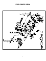
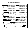
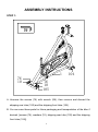
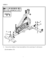
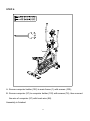
FLYWHEEL ELLIPTICAL TRAINER
S F - E 2 310
OWNER’S MANUAL
IMPORTANT!
PLEASE READ THIS MANUAL CAREFULLY BEFORE USING THE BIKE.
For Customer Service, please contact: [email protected]
Important Safety Information
We thank you for choosing our product. To ensure your safety and health,
please use this equipment correctly. Please read the information below carefully
before using this equipment.
1. It is important to read this entire manual before assembling and using the
equipment. Safe and effective use can only be achieved if the equipment is
assembled, maintained and used properly.
2. Before starting any exercise program you should consult your doctor to
determine if you have any medical or physical conditions that could put your
health and safety at risk, or prevent you from using the equipment properly.
Your doctor’s advice is essential if you are taking medication that affects
your heart rate, blood pressure or cholesterol level.
3. Be aware of your body’s signals. Incorrect or excessive exercise can
damage your health. Stop exercising if you experience any of the following
symptoms: pain, tightness in your chest, irregular heartbeat, extreme
shortness of breath, lightheadedness, dizziness or feelings of nausea. If you
do experience any of these conditions, you should consult your doctor
before continuing with your exercise program.
4. Keep children and pets away from the equipment. The equipment is
designed for adult use only.
5. Use the equipment on a solid, flat, level surface with a protective cover for
your floor or carpet. To ensure safety, the equipment should have at least
0.5 meters of free space all around it
6. Before using the equipment, please make sure all the nuts and bolts are
securely tightened. Always use the equipment as indicated. If you find any
defective components while assembling or checking the equipment, or if you
hear any unusual noises coming from the equipment during use, stop
immediately. Do not use the equipment until the problem has been rectified.
7. There are many functions of the computer, in which the value will show up
when using the equipment. Please note that the value of the heart pulse
displayed on the monitor is an estimate for reference.
8. Wear suitable clothing while using the equipment. Avoid wearing loose
clothing that may get caught in the equipment
9. The maximum weight of user is 300 LBS.
10. Care must be taken when lifting or moving the equipment so as not to injure
your back.
11. The equipment is not suitable for therapeutic use.
12. Please keep this manual and assembling tools for future reference.
13. This equipment is designed for indoor and home use only, not intended for
commercial use.
1
45
109
41
110
42
32
33
39
7
30
26
17
2
23
29
108
87
27
43
16
10
9
3
86
60
59
S8
107
15
16
83
61
9
10
1
97
S6
106
76
10
83
96
105
84
91
76
10
85
86
96
91
2
13
41
76
10
69
42
93
91
90
73
33
26
20
17
5
46
32
33
110
8
34
22 35
3332
28
93 93
94
95
94 29
74
39
42
93
39
93
76
10
68 75
70
70
72
32
33
38
89
93
104
67
93
93
11
14
12
81 87 82
79
91
16
15
9
10
12
13
21 9
91
92
44
92
88
16
15
17
101
101
11
14
78
72
77
72 72
71
78
98 68
102
66
100
101
101
33
73 74 75
99
51
52 100
16
53
50
49
48
47
16
65 56 21
63
57 17
62
58 54
64
55
80 85
15
40
22
34
35
31
6L
17
35
36
4
S8-14-22
82
33 32
29
20
103
22
19
28
18
20
33 42
32
37 39
22
25
24
25
35
36
30
40
31
29
6R
22
18
17103
1920
22
23
24
EXPLODED VIEW
PARTS LIST
NO
DESCRIPTION
QTY
NO
DESCRIPTION
QTY
1
Main frame
1
37 Left pedal 395*160*52
1
2
Front stabilizer
1
38 Right pedal 395*160*52
1
3
Rear stabilizer
1
39 Bolt M8*45*20*S14 grade A
4
4
Left handle bar
1
40 End cap J40*25*15
2
5
Right handle bar
1
41 End cap J60*30*15
2
2
42 Alloy wrap Φ28*4*φ24*12*Φ16.1
4
6L/R Left and Right Swing rod
7
Left pedal post
1
43 Left nut 9/16*20*H8*S22 L
1
8
Right pedal post
1
44 Right nut 9/16*20*H8*S22 R
1
9
Screw M10*25*S6
4
45 Left pedal bolt Φ16*121.5*24*9/16*S8
1
10 Washer d10*Φ20*2
8
46 Right pedal bolt Φ16*121.5*24*9/16*S8
1
11 End cap J80*40*18
4
47 Knob M10*φ49*46
1
12 Transport wheel Φ71*Φ19*24
2
48 Brake rod Φ10*320*30*100
1
13 Screw φ7.8*30*M6*15
2
49 Spacer 20*20*120
1
14 Screw M6*12*S5
2
50 Spacer Φ11*Φ16.5*80 11g
1
15 Foot pad M10*30*Φ52*49
4
51 Spring Φ2.0*Φ15*54*N12
1
16 Nut M10*H7*S17
6
52 Square nut 16*16*25*M10
1
17 Alloy bush Φ38*5*Φ34*15*Φ25.4
6
53 Nut M6*H14*S10
1
18 Bolt M8*16*S14
2
54 Screw M6*10*Φ12
1
19 Washer d8*Φ32*2
2
55 Spring piece t2.0*15.8*153
1
20 Spring washer d8
4
56 Brake block 12*25*138
1
21 Wave washer d26*Φ34*0.3
2
57 EVA pad 10*22*95
1
22 End cap S13
6
58 Cow leather pad t5*25*138
1
23 Bolt M8*40*20*S14
2
59 Bolt M6*12*S10
2
24 End cap Φ28*32*Φ50
2
60 Washer d6*Φ12*1.2
2
25 Foam grip Φ26*3*600
2
61 Screw M5*18*Φ12
1
26 Arc washer d8*Φ20*2*R16
2
62 Nut M5*H4*S8
1
27 Swing rod axle
1
63 Screw M5*10*Φ10
1
28 Nut M8*H16*S13
2
64 Screw M5*20*Φ8.5
1
29 Plastic bush Φ32*3*Φ28*16*Φ14.3
4
65 Nut M5*H9*S8
1
30 Spacer Φ14*Φ8.3*48
2
66
Inertial wheel
20*Φ460*38*30*Φ40*4
1
31 Bolt M8*65*30*S14,grade 8.8
2
67
Inertial axle
Φ12*162*M12*1.0*30*50
1
32 Washer d8*Φ16*1.5
6
68 Bearing 6001-2RZ NBK
2
33 Nut M8*H7.5*S13
8
69 Small chain wheel two ways 16 teeth
1
34 Bolt M10*42*20*S17
2
70 Nut M35*1*Φ41*3
2
35 Washer d10*Φ25*2
4
71 Spacer Φ18*Φ12.1*8
1
36 Nut M10*H9.5*S17
2
72 Nut M12*1*H6*S19
4
3
73 Nut M12*1*H19.5*S19
2
92 Screw M5*20*Φ8.5
2
74 Washer d12*φ24*2.0
2
93 Screw ST4.8*16*Φ10
8
75 Adjusting screw M8*83*Φ12*5
2
94 Screw M5*12*Φ8.5
2
76 Screw M10*16*S6
4
95 Washer d5*Φ10*1
2
77 Sensor stopper
1
96 Washer φ6.5*Φ25*6
2
78 Screw M5*10*Φ10
3
97 Computer
1
79 Big chain wheel
1
98 Trunk wire
1
80 Left crank
1
99 Sensor
1
81 Chain 1/2”*1/8”*106 KYC
1
100 Screw M6*12*Φ12
2
82 Crank cap Φ25*7
2
101 Sensor wire holder Φ12*11*Φ3
4
83 Bearing 6004-RZ NBK
2
102 Computer holder
1
84 Middle axle Φ20*146*37*74.5
1
103 D shape washer
2
85 Jump ring d20
2
104 Shipping front tube
1
86 Wave washer d20*Φ26*0.3
2
105 Shipping rear tube
1
87 Nut M10*1.25*H7.5*S14
2
106 Allen wrench S6
1
88 Inner chain cover
1
107 Allen wrench S8*33*80
1
89 Outer chain cover
1
108 Spanner S8 S14 S22
1
90 Front chain cover
1
109 Spanner S13-14-15
1
91 Fixing piece t0.8*11
5
110 Wave washer d17*Φ25*0.3
2
4
HARDWARE PACKAGE
5
ASSEMBLY INSTRUCTIONS
STEP 1:
1
76
10
104
76
10
105
A. Unscrew the screws (76) with wrench (S6), then remove and discard the
shipping rear tube (105) and the shipping front tube (104).
B. You can save these parts for future packaging and transportation of the bike if
desired. {screws (76), washers (10), shipping rear tube (105) and the shipping
front tube (104)}
6
STEP 2:
9
10
9
10
1
2
3
A.
Secure front stabilizer (2) and rear stabilizer (3) to main frame (1) with screws
(9) and washers (10).
7
STEP 3:
S13-14-15
S14
S8-14-22
22
18
20
19
103
21
27 21
5
4
1
103 19 20 18 22
A. Attach swing rod axle (27) into main frame (1), insert wave washer (21) into the
swing rod axle (27) on both sides;
B. Secure left handle bar (4) and right handle bar (5) to swing rod axle (27) with
bolts (18), spring washers (20), washers (19) and D shape washers (103);
* NOTE: In order to tighten bolt #18 on both sides, use a spanner to hold on the
left side, and to tighten the right side. You are required to use both spanners.
C. Attach end cap (22) on bolt (18).
8
STEP 4:
S22
S8
S8-14-22
4
23
20
28
26
5
6L
22
45
110
22
7
26
20
31
23
28
80
6R
22
31
43
22
79
8
44
110
46
A. Secure swing rod (6L) to left handle bar (4) and Swing rod (6R) to right handle
bar (5) with bolts (23), arc washers (26), spring washers (20) and nuts (28);
B. Secure right pedal post (8) to crank on the big chain wheel (79) with right pedal
bolt (46), wave washer (110) and right nut (44) by screwing clockwise;
C. Secure *left pedal post (7) to left crank (80) with left pedal bolt (45), wave
washer (110) and left nut (43) by screwing *counter-clockwise;
D. Attach end cap (22) on both sides of the bolt (31).
9
STEP 5:
39
37
7
32
33
39
38
8
32
33
A. Secure left pedal (37) to left pedal post (7) with bolts (39), washers (32) and
nuts (33);
B. Secure right pedal (38) to right pedal post (8) with bolts (39), washers (32) and
nuts (33).
10
STEP 6:
97
78
100
102
100
98
1
A. Secure computer holder (102) to main frame (1) with screws (100);
B. Secure computer (97) to computer holder (102) with screws (78), then connect
the wire of computer (97) with trunk wire (98).
Assembly is finished.
11
MAINTENANCE
I
22 33
31
22
II
30
After a period of time, the grease in the joint will become dry and it might
cause noise. Please follow instructions on how to lubricate the joint below:
Remove end caps (22), bolt (31) and nut (33) as diagram Ⅰ, then remove
spacer (30) as diagram Ⅱ, and add some grease on the surface and inside of
spacer (30) to decrease the rub, after finishing it, please assembly spacer
(30), bolt (31), nut (33) and end caps (22) back.
Version: Mar 10, 2014
12