1
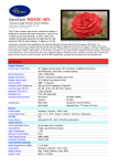
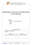
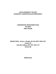
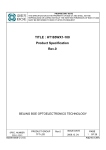
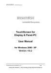
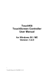
DanoTech
Capacitive Touch Sensor
Installation Guide
Version : D_03
Date : 2012 / July
Index
Chapter 1 Preparation for Installation ............................................... 3
Open Your Container..............................................................................3
Preparing the Monitor ...........................................................................4
Preparing your tools and materials........................................................4
Chapter 2 Mounting DanoTech Capacitive Touch Panel...................... 5
Touch Sensor Care and Cleaning............................................................5
Basic Mounting Procedure.....................................................................5
Sealing Tape ...........................................................................................6
Tail Considerations .................................................................................7
Double-Side Sponge Tape ......................................................................7
The Back Shield ......................................................................................8
Touch Panel Mounting Steps..................................................................8
Chapter 3 Installing the Touch Screen Controller ............................... 9
Controller Outline Dimension ................................................................9
Controller Specifications ........................................................................9
Positioning Your Controller ..................................................................10
Interface Selection ...............................................................................10
Controller Mounting Steps...................................................................11
Turning On Your System .......................................................................11
Installing Software................................................................................12
Calibrating the Touchscreen.................................................................12
Chapter 4 Touch Screen Application Considerations ........................ 15
Metal Enclosures..................................................................................15
Electrical Field Affection ......................................................................15
Danotech Touch Systems Support Service...........................................15
DanoTech Installation Guide
2
CHAPTER 1
Preparation for Installation
Important Safety Information
CAUTION
Please handle the touch sensor with care to avoid breaking the glass. Be aware of
cracked or broken touch sensors with sharp edges.
Open Your Container
Before perform your installation, please open the shipping container and check
following necessary components for a complete installation.
A capacitive touch panel
A touch screen controller board
Y converter cable (switch to USB or RS232 interface)
A Serial (RS-232) cable or USB cable
A CD-ROM, which including driver software and documentation.
Extension cable (optional)
The following components are needed for your integration:
A Danotech touch sensor
A touch screen controller board
Y converter cable
Controller driver
Remove all tapes on the package, and handle the touch panel carefully, place it on a
clean, anti-static pad, then remove the protective film and clean the touch panel with
natural cleaner and soft wiper.
DanoTech Installation Guide
3
Preparing the Monitor
CAUTION
Keep the monitor powered off when assembling and disassembling the touch
sensor. There may be hazardous voltages present in the display.
First, please check the condition of the monitor before you install the touch panel
into the monitor. If the monitor is working properly, please turn off the power,
disconnect all cables and power plugs, disassemble your monitor then prepare all of
tools and material you need before installation.
Preparing your tools and materials
You should have all parts of the touch system and tools which include:
Screwdriver
Screws for controller
Natural cleaner and soft wiper
Sealing tapes
Double-side sponge tapes
Plastic washers or spacers
Knife
Mounting poles for controller
Tape for affixing the tail of touch
panel
Clean soft cloth and glass cleaner
for the display and touch sensor
CAUTION
Dano’s coating technology can meet 9H pencil hardness. Please do not place any
mental or sand on the touch screen surface. For example: key, screwdriver,
knife…
DanoTech Installation Guide
4
CHAPTER 2
Mounting DanoTech Capacitive Touch Panel
This chapter describes how to install the touch sensor on the flat display properly.
Touch Sensor Care and Cleaning
CAUTION
Do not let any metal (LCD housing, screws …) physically contact the front or sides
of touch sensor and tail. This may induce an electrical field effect and confuse
the controller.
It’s recommended to use an isopropyl alcohol and water solution ration of
50:50 for cleaning your touch sensor.
Always dampen the cloth and then clean the sensor.
Please use soft and lint-free cloth for cleaning purpose.
Ensure no any metal material or sand on the surface of the touch sensor
before you start cleaning the touch sensor. Especially when you add
pressure on a small material such as sand and then scratch the surface. This
action always damages the touch sensor and unrecoverable.
Basic Mounting Procedure
Below is the exploding chart of assembling the touch panel and monitor:
Front
Display
Sealing Tape
LCD Panel &
Chassis
Controller Board
Housing
Touch Sensor
Double-Side
Sponge Tape
Back Shield
Rear display
casing
Figure 1
DanoTech Installation Guide
5
DanoTech Capacitive Touch Panel fits most monitors from 10.4 inches to 32 inches.
The installation components from left to right as Figure 1 include:
Front display housing (Front Bezel)
Sealing tapes
Touch sensor
Double-side sponge tapes
LCD panel and chassis
Touch controller and back shield
Rear display casing
Anti-ESD wrist strap
Sealing Tape
CAUTION
Please mount the sensor directly to LCD. Avoid mounting LCD and sensor independently to a common bezel. It may cause erratic operation and false touches,
because the gap between the sensor and the LCD may be influenced due to stresses
applied to the bezel.
It is important for using sealing tapes to prevent dust, dirt, water, and particle.
Normally, it’s recommended to use single-side sponge tape as the sealing tape.
Please simply align and adhere the tape to the front bezel edge. The tape should
contact the sensor perimeter to ensure a good seal without touching the viewing
area to avoid interference. Do not adhere the tape to the sensor surface.
The gap between front bezel and touch sensor is important for good assembly.
Especially, if the bezel is metal or has conductive paint, please keep a proper distance
to avoid interference from the bezel. The optimal distance is 6mm for metal
enclosures, but it is adjustable per your system design.
Please mount the sensor directly to LCD. Avoid mounting LCD and sensor independently to a common bezel. The gap between the sensor and the LCD may be
influenced, while the stresses are applied to the bezel. It may cause erratic
operation and false touches.
DanoTech Installation Guide
6
Please avoid attaching the sensor to a door, if the display is attached to a cabinet for
the same reason as above. If this cannot be avoided, do not operate the sensor with
a partially open door. Upon closing the door, always reset the controller. It can
prevent erratic operation such as jittery cursor and variable offsets.
Tail Considerations
CAUTION
This tail is an electrical connection and not designed for high stress. Please take
care with the tail when assembling. Do not bend the tail with constant stress
and be sure it will not move freely after assembly.
Never pick up the touch panel by holding the tail.
If necessary, the tail can be bent only once and not place constant stress on
the tail.
Never bend the tail close to the edge within 5 mm from the panel edge.
After the assembly of the touch panel and LCD panel, affix the tail to the
LCD panel chassis.
Never route the tail and the extension cable near the backlight inverter and
power supply of the LCD panel in order to reduce the EMI interference.
If necessary, the tail can be extended by an optional extension cable.
Keep the connection and routing as smooth as possible. Do not bend the
extension with a sharp angle.
Double-Side Sponge Tape
The touch panel must be mounted onto LCD panel by double-side sponge tape. It will
keep the touch panel away from LCD metal frame to prevent electric interfere. Please
make sure the gap between sensor and LCD will not vary due to compression or
expansion from touch forces or temperature changes. The sponge tape should have a
minimum thickness of 1.5mm. (3M VHB 4956 for recommended) to mount touch
panel on the LCD display for the optimal performance of the touch sensor.
DanoTech Installation Guide
7
The Back Shield
If the back shield of the LCD module is removed, please make sure to put back the
back shield. It can protect the controller from electronic noise and get the best
performance.
Touch Panel Mounting Steps
Align the center of the viewing area of the touch panel to the center of the
LCD display area.
Use natural cleaner and soft wiper to clean the touch panel.
Apply the double-side sponge to the perimeter of LCD panel surface
without gap.
The sponge should not form a full seal. Preserve 1-2 mm gaps at the
corners for ventilation to avoid damaging the LCD with temperature and
pressure equalization issues.
Front
Display
Front
Display
Attach the touch panel to LCD panel carefully. Make sure there is no dirt,
dust nor particles between them, and align for the correct position.
DanoTech Installation Guide
8
CHAPTER 3
Installing the Touch Screen Controller
This chapter describes how to install the controller properly. In order to get the
best performance and stability, please follow the instructions and recommendations
below.
Controller Outline Dimension
Figure 2
Controller Specifications
Circuit Board Dimension
Power Requirements
Operating Temperature
Interface
DanoTech Installation Guide
62mm x 33mm (2.445inches x 1.299inches)
D.C.+5V, external 5~12V unregulated power
(Maximum 65mA, typical 55mA, 50mV peak to peak
maximum ripple and noise)
-40 to 80 ℃
Bi-directional RS-232 serial communication
USB: 2.0 compliant
9
Protocol
RS232:No parity,8 data bits,1 stop bit,9600
baud(N,8,1,9600)
USB: Full Speed, USB 2.0 compliant
Resolution
2048×2048
Report rate
Adaptive Sampling Rate. Max. 180 points/sec
Response time
Max. 25 ms
Electro-Static Discharge (ESD)
Contact: 8KV / Air: 27KV
Positioning Your Controller
Before installing the controller, please wear Anti-ESD wrist strap first. Make sure that
there is enough internal space for accommodating touch panel controller. Choose a
proper location for the controller on the back side of the LCD chassis. Determine the
positions of the controller mounting holes. Drill at least two mounting holes and tap
the holes for mounting screws. Choose proper poles for the electrical isolation
between the controller and the LCD chassis.
CAUTION
Ensure the controller board is proper grounding to the chassis with the
mounting screws. This can provide a stable reference voltage for
controller and prevent from ESD shock.
Do not positioning the controller near the backlight inverter or LED power
supply.
Interface Selection
Upon your selection of computer/controller interface (RS232 or USB), simply connect
the cable (RS232 or USB) to the proper interface of the Y converter cable.
DanoTech Installation Guide
10
Figure 3-1
Figure 3-2
Controller Mounting Steps
1. Secure the touch controller onto the back side of the LCD chassis by using proper
size screws.
2. Reconfirm controller interface selection (RS232 or USB), please see Figure 3.
3. Connect the tail of touch panel to the locking AMP connector on the controller,
and affix the tail to the chassis of LCD panel by tape. Be aware not to bend the
tail more than once as mentioned earlier.
4. Connect your Serial or USB cable to the controller and route the other side of
cable out of the rear case. Secure the cable to the case as well.
5. Test your touch controller by connecting the interface cable to your computer.
For serial type controller, connect both PS/2 and RS232 cables to the PS/2 port
and RS232 port on your computer respectively. For USB type controller, use a USB
cable to connect the controller with your computer. After the connection, the LED
light should keep blinking.
6. Reassemble the LCD panel and rear cover.
Turning On Your System
Make sure all cables and screws are connected properly and fixed. Then open your
monitor and computer.
DanoTech Installation Guide
11
For most operation systems today, it should find a new device
automatically and have a basic function for operation.
When we touch the touchscreen, the led on the touchscreen controller will
have a corresponding signal light.
If we may find a new device on the operation system, we can make sure
that the device is connected well.
For the next step, we need to install the correct driver for the new device,
touch controller device.
Congratulation! You successfully installed the touch controller and connected the
touch screen to your computer. You are now ready for the final task.
Installing Software
DanoTech provides user the following operation systems for touch panel system.
Windows 95 / 98 / ME / NT4 / 2000 / XP / XP Tablet PC Edition / Vista / 7
Embedded XP
Windows CE 2.12 / 3.0 / .NET / 5.0 / 6.0
Linux RedHat / Fedora / Mandrake / SuSe / YellowDog / Debian / Ubuntu
(up to kernel 2.6 )
iMac. OS9.x / OSX
MS-DOS
Please install your driver and application according to User’s Manual in the CD-ROM.
Calibrating the Touchscreen
We provide the functions list below for calibration and linearization. Calibration
aligns the touch sensor with the underlying monitor and defines the dimensions and
directions of the image areas. The Linearization function is used to compensate the
touchscreen linearity. After linearization is completed, the linearity of the
touchscreen will be shown in the Linearity Curve window. In drawing test window,
users can verify the panel linearity, calibration capability, and drawing line quality.
Calibration
9points Linearization
DanoTech Installation Guide
12
25points Linearization
Draw Test
1. 4 points calibration
It needs calibration before the touchscreen can work accurately. Whenever the
user feel the accuracy lost, user can do calibration again to get a more accuracy
touch function. Pressing this button, a new window will be popped-up at the
location when the touchscreen was mapped to area for this touch system to
guide the user do 4 points calibration. User should follows the guide to touch
and hold the blinking symbol in the calibration window until it shows “OK” to
make sure that the utility can gather enough data for computation.
Touch and
Release Target
2. Clear and Calibration
DanoTech Installation Guide
13
Press this button to erase the 25 points calibration/linearization parameters and
force user to do 4 points calibration again. After 25 points calibration data was
clear, the 4 points calibration data will be invalid. It needs to do 4 points
calibration.
3. Linearization
Linearization ( 9 or 25 points calibration ) function is used to compensate the
touchscreen linearity. After linearization completed, the linearity of the
touchscreen will be shown in the Linearity curve window.
Pressing this button, a new window will be popped-up at the location when the
touchscreen was mapped to area for this touch system to guide the user do 25
points calibration. User should follows the guide to touch and hold the blinking
symbol in the calibration window until it shows “OK” to make sure that the utility
can gather enough data for computation.
4. Draw Test
This function is used for accuracy and performance check. Press this button and a
new pop up window will be popped up in the location where the touchscreen
was mapped to the touch system as below,
User can press the ‘Clear’ button to clear the window. Press ‘Quit’ button to
terminate this draw test.
DanoTech Installation Guide
14
CHAPTER 4
Touch Screen Application Considerations
Metal Enclosures
It’s strongly recommended to use plastic bezel for application consideration.
In the design phase, avoid metal bezel whenever possible.
If your current product has a metal bezel, make sure it does not directly
contact the front or sides of touch sensor.
The metal bezel should be appropriately grounded and very rigid. Use
insulating tape or gasket as a spacer.
Some plastic bezels with conductive paint could act as a metal bezel. So the
same design rules should be applied in these instances.
If there is a metal door and sometime needs to be open/close. The stray
capacitance might be changed and a reset sequence will start for few
seconds.
For metal enclosures or bezels the gap to the touch sensor at least need
6mm.
Electrical Field Affection
Any electrical devices that generate electrical fields can cause problems.
Such as inverters inside the LCD monitor or radio transmitters from the
environment.
Danotech Touch Systems Support Service
Please visit Danotech official website at http://www.danotech.com.tw/ , and you can
download touch screen drivers and get related data sheet for your requirement.
You may contact Danotech for any technical support by calling, a fax or email.
Tel:
+886-3-4757888
Fax: +886-3-4859158
E-mail: [email protected]
DanoTech Installation Guide
15