1
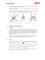
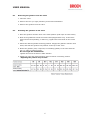
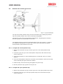
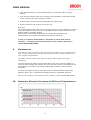
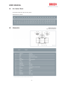
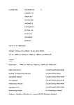
Contents
1.
General information...........................................................................................................2
1.1
BROEN BALLOMAX® Steel Ball Valves ...............................................................2
1.2
Approvals ............................................................................................................................2
1.3
Quality Management.....................................................................................................2
2.
Preoperational Instructions and Precautions ....................................................2
3.
Plates..........................................................................................................................................3
4.
Transport and Storage .....................................................................................................3
5.
Installation and Welding ................................................................................................4
5.1
Installation.........................................................................................................................4
5.2
Welding.................................................................................................................................4
6.
Commissioning and Use ..................................................................................................5
6.1
7.
Commissioning Test Pressures...............................................................................5
Operation .................................................................................................................................5
7.1
Valves operated by handle........................................................................................5
7.2
Valves operated by gearbox.....................................................................................5
7.3
Valves prepared for mounting of gearbox/actuator .................................5
8.
Dismounting/remounting the manual gearbox ................................................5
8.1
Removing the gearbox from the valve...............................................................6
8.2
Mounting the gearbox on the valve .....................................................................6
8.3
Adjusting the position stop screws......................................................................7
8.3.1
To adjust the closed position stop ..............................................................7
8.3.2
To adjust the open position stop .................................................................7
9.
Maintenance ...........................................................................................................................8
10.
Maximum Allowable Pressure at Different Temperatures ..........................8
11.
Kv Value Chart ......................................................................................................................9
12.
Materials ...................................................................................................................................9
USER MANUAL
1.
General information
1.1
BROEN BALLOMAX® Steel Ball Valves
The BROEN BALLOMAX® ball valve is intended for installation in District heating and
cooling networks operating with treated water not decomposing plain carbon steel
and materials in O-rings and seats.
The valve body is made of carbon steel and the shaft and the ball of stainless steel.
The ball seals are made of carbon reinforced Teflon (PTFE). The stem sealing is made
with FPM (Viton) and EPDM O-rings.
The valve is bi-directionally tight and can be installed in all positions.
1.2
Approvals
BROEN BALLOMAX® steel ball valves have been approved according to the
requirements of Pressure Equipment Directive (PED) 97/23/EC, module H. Module H
is the module for complete quality control.
1.3
Quality Management
BROEN A/S is a certified ISO 9001 company. The ISO certification is approved by
Bureau Veritas Quality International Ltd., London, one of the leading international
authorities on ISO certification. Bureau Veritas spent three days at BROEN to check if
our Quality Management system was adequate. BROEN spent an additional 12
months on analyses and discussions and made substantial investments to meet the
highest demands for quality management.
ISO 9001 is the hardest approval to achieve within the ISO 9000 standards. It fulfils
the requirements of EN29001 and BS 57, part 1, covering all processes of production
flow and customer service – from the very first product idea, through drawings,
materials, production as well as inspection and testing procedures, packaging,
shipping, staff training, contracts and technical documentation, maintenance and
claim handling.
2.
Preoperational Instructions and Precautions
Please read and note the following instructions before handling and operating the
BALLOMAX® ball valves:
• Check that the valve is suitable and approved for the medium and application in
question.
• Do not exceed temperature and pressure limits for the valve (see chapter 10).
Note: Not suitable for steam.
• Be aware. Valves installed at pipelines in operation can be hot. Be careful not to
get burned.
• In case the valve is used as an end stop valve at the pipeline, a closing cap or end
flange must be mounted after the valve, and the valve should be left in open
position.
2
USER MANUAL
• In order to secure safe operation the manual gear or actuator must not be
removed or dismantled if the valve is pressurized or/and has a flow.
• In case there is a need for changing O–rings at the stem, BROEN BALLOMAX should
be consulted for guidance and safety instructions.
3.
Plates
The identification plate is located at the valve body.
• BALLOMAX® - the name of the valve
• DN 50 – the DN size of the valve
• PN 40 – the pressure class of the valve
• Material: P235GH / St. 37.0 – primary materials in the valve
• Temp. – minimum and maximum temperatures for the application of the valve
• Fluid Group 2 – fluid group according to 97/23/EC
• Date – year and month of production and test
• BROEN A/S DK 5610 Assens – name and address of manufacturer
• CE 0041 – CE mark and the number of the notifying body
• www.broen.com – manufacturer’s website
• 500531 – plate number
4.
Transport and Storage
It is important that you check that the valve and its parts have not been damaged
during transport. Please also check that the contents of the delivery are according to
agreement - valve type, size, numbers, etc.
Information regarding possible damage, defects or irregularities compared to the
agreement must be reported immediately to BROEN BALLOMAX.
3
USER MANUAL
Store the valve at a clean and dry place before the installation. Remember to remove
the flow port protection before installation.
Use lifting ropes when large size valves are to be lifted. Do not lift the valve from its
actuator, stem or handle.
If in doubt about the weight of the valve to be lifted, please check its weight from the
BALLOMAX® catalogue or at the BROEN website - www.broen.com.
5.
Installation and Welding
5.1
Installation
The pipelines must be cleaned properly before installing the valves, otherwise
possible impurities may damage the valve surface and sealings. Before installation,
the inside of the valve must also be checked for impurities and dirt that the valve
may have been exposed to during storage or transport. Make sure that the valve’s
maximum and minimum temperatures are not exceeded! The maximum operational
pressures and the minimum/maximum temperatures are stated on the valve
identification plate.
Do not remove the manual gear or actuator from the valve unless absolutely
necessary. If the manual gear or actuator must be removed during or after the
installation, please contact BROEN BALLOMAX or see chapter 8.
5.2
Welding
Electric welding (TIG, MIG) is recommended for all BROEN BALLOMAX® steel ball
valves. Valve DN 150 and bigger valves must be welded on to the pipeline by use of
electric welding.
Do not overheat the valve during welding – there is a risk of damage to the sealings.
The welder must be properly qualified to undertake the welding procedure.
The ball must be in fully open position during installation.
Cool down the valve (after welding) before normal operation. The valve may not be
opened/closed after the welding before it has cooled down.
4
USER MANUAL
6.
Commissioning and Use
After the installation of the valve, the pipeline must be flushed thoroughly.
6.1
Commissioning Test Pressures
All valves (100 %) have been tested at the BROEN BALLOMAX production facilities.
In case a pressure test of the system is required – be aware:
• The build-up of pressure must be done slowly and gradually in order to avoid
pressure shocks/hammering.
• During the pipeline pressure testing (1.5xPN) the valve must be open.
Be aware:
• The shut-off valves are designed to be fully open or closed. Check that the valve is
either in open or closed position against the stopper.
• If the valve should be used as an end stop valve at the pipeline, a closing cap or
end flange should be mounted after the valve, and the valve should be left in open
position.
• When emptying a system in operation the valve has to be turned into a half-open
position in order to remove all liquid behind the ball. This is especially important
when the pipelines may be exposed to temperatures below 0ºC.
7.
Operation
7.1
Valves operated by handle
When the valve is open, the handle is
aligned with the pipeline.
7.2
Valves operated by gearbox
The valve opens when the manual gear is turned clockwise.
7.3
Valves prepared for mounting of gearbox/actuator
The position indicator line at the end of the stem shows the position of the ball
versus the stem.
The opening and closing of valves must be done slowly and carefully in order to
minimize pressure shocks in the pipeline system. This is especially important for big
dimensions (DN 150 and bigger).
8.
Dismounting/remounting the manual gearbox
The following procedures must be carried out by skilled and experienced
personnel only. Before starting the procedures - read the manual carefully
and contact BROEN BALLOMAX if any questions.
5
USER MANUAL
8.1
Removing the gearbox from the valve
1. Close the valve.
2. Remove the four (or eight) mounting screws and lockwashers.
3. Remove the gearbox from the valve.
8.2
Mounting the gearbox on the valve
1. Place the gearbox and the valve in the same position (both open or both closed).
2. Most of the gearboxes include an insert bush equipped with a key. If the insert
bush is delivered separately, or falls out, (re)place the insert bush in the correct
way.
3. Select the desired gearbox mounting position. Engage the gearbox with the valve
shaft, and slide the gearbox into position on the top of the valve.
4. Mount the gearbox (and, if required, an insulating gasket) to the valve with the
four (or eight) mounting screws.
Do not forget the lockwashers!
Tighten the screws as shown in table A below.
5. Adjust the open and closed positions stops as shown in following section.
“Adjusting the position stop screws”.
6
USER MANUAL
8.3
Adjusting the position stop screws
The open and closed position stops prevent the actuator from rotating beyond the
open and closed position of the valve. Each stop is adjustable.
The stops are not preset by the gearbox manufacturer. Adjusting has to be done
when the gearbox is (re)mounted on the valve.
The adjustment has to be done as described below. We refer to figure T.1 (above)
for component identification. We also refer to the valve instructions for specific
closed position requirements for the valve.
8.3.1
To adjust the closed position stop
1. Remove the protection cap (A) from the jam nut on the closed position stop
screw.
2. Loosen the jam nut (B) on the closed position stop screw and loosen the stop
screw a few turns.
3. Turn the hand wheel (or other operating device) so that the valve is in closed
position.
4. Turn the closed position stop screw clockwise until resistance is felt from the stop
screw contacting the gear inside the actuator.
5. Hold the stop screw from turning and tighten the jam nut (B).
6. Put the protection cap (A) back on the jam nut.
8.3.2
To adjust the open position stop
1. Remove the protection cap (A) from the jam nut on the open position stop screw.
2. Loosen the jam nut (B) on the open position stop screw and loosen the open
screw a few turns.
7
USER MANUAL
3. Turn the hand wheel (or other operating device) so that the valve is in open
position.
4. Turn the open position stop screw clockwise until resistance is felt from the stop
screw contacting the gear inside the actuator.
5. Hold the stop screw from turning and tighten the jam nut (B).
6. Put the protection cap (A) back on the jam nut.
Be aware:
The exact position of the ball in open and closed position is very important in order to
secure the tightness of the valve. If it is possible to see the inside of the valve, the
position must be carefully checked.
Open position: ball exactly aligned with connecting ends and seat rings.
Closed position: full contact/overlap between ball and seat rings.
If case of a need for disassembly or assembly of valves with electric
actuators – carefully follow the instructions in the actuator manuals or
contact BROEN BALLOMAX.
9.
Maintenance
The valves do not need extra service under normal conditions, but to guarantee the
good working of the valves, opening and closing the valve a couple of times every
year is highly recommended.
The proper function of the valve requires a proper water quality and proper
installation.
The valve housing is made of carbon steel and as such not corrosion resistant. To
avoid corrosion coming from outside, the valve will either have to be installed in dry
surroundings or it must be protected by watertight insulation or other surface
protection.
If needed, the upper O-ring(s) of the stem can be replaced without draining the
pipelines. Note: only on depressurized pipelines with no hydrostatic pressure.
Be aware of all special circumstances and if necessary, contact BROEN BALLOMAX.
10.
Maximum Allowable Pressure at Different Temperatures
8
USER MANUAL
11.
Kv Value Chart
Kv Values when the valve is fully open:
Reduced bore valves
12.
Materials
9