1
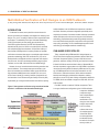
Coverage driven Verification
In coverage-driven verification an engineer can
keep track of which part of the protocol being verified
in the run. With coverage in place for a given protocol,
an engineer can easily tell what tests need to be
written to cover all the features of the device. Since
verification is directly related to the time and resources
available, most teams focus mainly on the newly added
blocks and interfaces in the design. A major source of
uncertainty is those bugs in previously verified blocks
stemming from the integration of new design blocks.
The use of coverage-driven verification is an antidote,
showing when you have eliminated enough risks/bugs
from all parts of your design.
PCIe OVM Verification environment
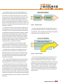
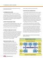
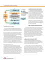
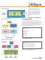
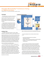
The testbench structure of PCIe MVC uses OVM components.
PCIe MVC agents are made that stimulate the link and generate the
transactions. Each PCIe MVC agent has a corresponding sequence
with a set of configurations. Use of OVM methodology, components
and templates helps to structure the primary and secondary test
sequences. PCIe MVC comes with the three types of pre-defined
sequences: basic, general and scenario-based.
Basic sequences are the building blocks for stimulus generation
and are customizable. General sequences are layer-specific, initiating
the various kinds of transactions on to the bus depending upon the
layer. Scenario-based sequences are specific to the device behavior
and depend on the transaction being initiated by the requester or
completed by the completer. These also include coverage-specific
sequences that initiate the legal and illegal transactions, and thus help
to achieve full coverage of the DUT.
The random requester sequences issues the random legal
tlp transaction traffic on the bus continuously per the provided
configuration. These sequences can also be configured for initiating
the illegal transaction. The completer sequences respond to the
incoming transactions with the legal and illegal packets. The lower
physical layer also provides sequences to generate LTSSM-directed
scenarios along with the power management and Gen1, Gen2 and
Gen3 (or vice-versa) data rate transition sequences. Physical layer
error sequences allow for injection of all types of 8b/10b errors.
36
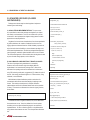
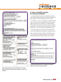
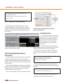
XML plan capturing protocol
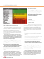
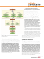
The compliance checklist provided by PCI-SIG is ported in an Excel
sheet as the test plan; from this it’s straightforward to generate the
XML test plan, which can be easily linked to the simulation coverage
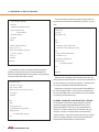
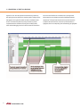
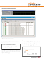
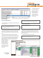
results provided by Questa in the form of the Unified Coverage
Database (UCDB). This database is the repository for all coverage
information – including code coverage, cover directives, cover points
and assertion coverage – collected during the simulation by the
Questa infrastructure. Questa provides the ability to merge the XML
test plan with all coverage results in the form of UCDB, which is
accessible both via log file and GUI.
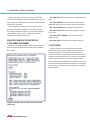
Compliance checklist items
Mapping of English protocol definitions to a mechanism for
verification can be a major challenge. It’s easy to underestimate the
workload and get confused between checking a single scenario and
proving that a specific feature works in all scenarios.
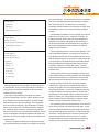
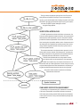
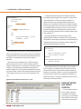
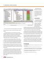
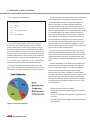
Consider an example: a certain PCIe compliance checklist item
says that permitted Fmt[1:0] and Type[4:0] field values are shown in
the spec table. All other encodings are reserved. Fmt and Type fields
determine the type of transaction layer packet (TLP) and associated
decoding. Without a metric or indicator that reports the types of TLPs
generated and transmitted, the information from the DUT is almost
meaningless. Further complicating matters is the fact that there are
128 possible field values, while only 25 are valid.