1
Afdeling der Elektrotechniek
Technische Hooeschool Eindhoven
Vakgroep AutO~3tisch Systeemontwerpen
,; n l (: ~ e 1""
do~~
3::
t i '/ e L a v 0
T,G.~.v3n
l..l tEd ito r !
Ooijen
C 0 III P
.3 C tor'
Rapport van het afstudeerwerk
uitgevoerd van 0ktober 1981 tot oktober 1982
in opctr.3cht van pref.
dr.
ing.
J.Jess,
onder Leiding va~ ir.
M.van der Woude.
Table of contents
Page
Summary.
.3
Chapter
'1
Introduction.
Chapter
2
Sticks.
Chapt er
3
Layout editor.
Chapter
4
Data structure •••••••
Chapter
5
Design rule checking ..••••.••••.••.••.•••. 19
Chapter
6
Compaction ••
Chapter
7
Conclusions, recommandations ••••••
Chapter
8
Description of program and subroutines .••. 27
Chapter
9
Description of error messages •...••.•••••• 40
Appendi x A
Figures ••.•••
Appendix
Bibl ;ography.
B
.4
• •7
.16
22
.25
.43
II
••••••••••••••••••••••••••••
49
PAGE 3
Summary.
This report describes a program made by T.G.M.van
Ooijen, student for masters degree at the Eindhoven
University of Technology. The purpose of the program
is threefold:
layout
The first part of the program is a symbolic
editor:
An
interactive program with wich a user can
build a circuit, consisting of
sticks
(symbolic
elements) on a grafics terminal.
The second part checks the circuit to see if there are
violations
against design rules,
rules concerning
minimum distances, minimum linewidth's etc.
The last part is the start of a compaction program,
a
program that will shift all elements together as far as
possible, without violating the design rules.
Interactive Layout Editor/Compactor
Chapter "1
Introduction.
PAGE 4
Interactive Layout Editor/Compactor
PAGE 5
The department of Electrical Engineering of the Eindhoven
University
of
Technology
is
planning
an
IC-production unit.
For this unit, wich will be.become
operational
in 1983,
IC's have to be designed at the
same university.
In the section ES, a group of students developed, in co-operation with professor J.Jess
and ir. H.van der Woude, a layout system to help future designers.
On the computer of the section ES, a
PDP 11/60 an interactive Fortran program was set up for
this purpose. We wanted this program to take over the
drawing of the geometrical layout from the designer, so
he can concentrate himself on the electronic design,
and on the relative placement of the elements (the topology of the layout).
One of the demands for an integrated circuit
is that
its surface stays as small as possible.
Because the
designer from now on only choses a good topology for
the elements, the program has to perform a "compaction"
on the l ayol_lt •
A few features such a program should contain are stated
below:
-Symbolic input: A line or transistor is placed as
a symbol in the layout.
-Input via a graphics terminal.
-Hierarchical structure:
It should be possible to
define a macro,
wich is a layout consisting of a
number of sticks and/or other macro's, and later use
this macro as one of the simple elements like a
lin e •
-Hierarchical database: The database should have
the same hierarchy, the contents of a macro appears
only once, and each other time the macro is used,
only a pointer to the macro should be added in the
database.
-The program has to be able to check whether the design rules (minimal distances, minimal linewidth's
etc.) have been violated.
-The symbolic has to be translated to a geometrical
layout.
-The program has to perform a compaction on the layout, if desired by the user.
-It has to be possible that a designer draws part of
the layout in the geometrical way.
Interactive Layout Editor/Compactor
PAGE 6
During the period 1 stayed in section ES , I worked on
three programs:
A symbolic
layout editor, a design
rule checker and a compactor.
Realized are the first
version of the layout editor (wich cannot handle hierarchical structures), and the design rule checker,
while the work on the compactor has been taken over by
X.Timmermans.
An improved version of the layout editor was made by
K.Delhij [5]. Major improvements are the hierarchical
structure, and a better database.
The functions the editor is able to perform are:
- Adding elements.
- Deleting elements.
- Drawing elements.
- Printing the array wich contains the
information about the elements.
- Retrieve the situation as it was
before the last command.
For further information, see chapter 3, The Layout Editor.
Information about
the symbolic elements itself
can be found in chapter 2: Sticks.
The design rule checker and compactor are described
in
chapter 5 and 6=
Design Rule Checking and Compactor.
In short, th~ design rule checker is able to detect the
following errors:
- Not allowed overlap ,of elements.
- Distances between elements that are smaller than
the minimal distances.
- Not closed lines (lines with dead ends).
- Not connected transistors or contacts.
- Double placed elements (elements of the same type,
that completely overlap each other).
Other design rules are enforced by the translation of
symbolic to geometric layout: Lines automatically get
their minimum width when translated (when the user did
not specify a special width, otherwise the width is
greater).
So far for this short overvieuw of my work.
I like to
thank everyone who helped with advises, specially my
coaches professor J.Jess and ir. M.van der Woude, and
also mr. H.O~Koopmans for his help concerning the computer.
I
Interactive Layout Editor/Compactor
PAGE 8
Before going into the details of the design process, we
should take a close look at the elements, called
"sticks", our symbolic layout consists of.
As there are, in NMOS, three layers for interconnecting
elements (diffusion-, polysilicon- and metallayer), we
also have three different symbols in the symbolic layout for these connections, each of them symbolizing one
of the aforementioned layers.
These three symbols are straight lines with a different
dashing.
A fourth line type is used only in the symbolic layout, having no meaning in the geometric
layout:
The RUNX-line.
This line (name from ( 3 ])
can't be used for connections, but only for boxes around groups of elements, and to write comment into the
symbolic layout.
See figure 2 in AppendiX A for these lines.
Normally a line gets a width that is equal to its minimal width (2 lambda, see below for lambda). However,
it is possible for a user to specify a width wich is
greater.
This is explained in chapter 3, the layout
editor. Also the size of transistors and contacts can
be ajusted in a similar way.
Other symbols used are the contacts, also called via's.
They connect the three layers of different type, and so
we find three of them:
-The polysilicon-metal contact (P-M contact, P-MCT
in the menu).
-The diffusion-metal contact (D-M contact, D-MCT in
the menu).
-The diffusion-polysilicon contact (Buried contact,
BURCT in the menu).
The next group of symbols consists of transistors, both
driver- and loadtransistors.
In fact a drivertransistor is nothing more than a crossing of a polysiliconand a diffusionline, but we chose to have a special
symbol for it. The benefits are obvious:
-When the user has to place a transistor by explicitly giving the command TRAN, the program will be
able to find all not desired transistors that result
from crossings of the two lines (diffusion and polysilicon).
I
Interactive Layout Editor/Compactor
PAGE 9
-Furthermore, the transistor symbol will make the
picture easy understandable for designers without
experiance with the program.
The symbol of the drivertransistor consists of two rectangles, drawn over each other. They re~resent the two
crossing lines, and are dashed in the same way as those
lines.
When a transistor is called "vertical", this
means that the polysilicon line is vertical,
and the
diffusion
line
is horizontal. Figure 2 in appendix A
shows the transistor symbols.
For a loadtransistor, a third rectangle is drawn, symbolizing the implantation area.
Another symbol that won't reappear in the geometric layout
like the RUNX-tine is the terminal, also called
pin. When a user places a box around a group of elements! there is need for a contact to the world outside
the box. Terminals are the only symbols that are allowed to be placed on the surrounding rectangle (box).
Lines may end on the surrounding rectangle, but only if
a terminal is placed on that end.
The last symbol is the box.
A box is the surrounding
rectangle of
a group elements, and consists of four
linepieces of type RUNX. However, it is stored in memory as one element, not as four.
The symbols used and their names are taken from "CABBAGE", C3J.
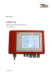
Figure 1 in appendix A (page 45) shows the screen after
the program
is started up.
On the upper right we see
the menu with the commands, below it the messages and a
legenda of used symbols and linetypes. Left we see the
window or picture window.
The picture window has scale marks and scale numbers
that indicate a grid. Sticks can be placed only on the
grid.
So when a user tries to place one of the sticks
besides a gridpoint, the program looks for the closest
gridpoint and places it there.
The width of the grid can be specified by the user (in
mm.).
However, the distance between two gridlines will
always be one lambda, lambda being the minimal stepsize
of the proces.
F.i.
a good value for lambda at the
moment is 3 micron. By specifying all distances
in
lambda the
inputprogram will be independent of future
improvements of the proces that will force lambda down.
Note: The menucommand IMPL is not operational anymore, and won't reappear in a next version.
Figure 2 in appendix A (page 46) shows the sticks,
the
grid has a width of 20 mm. The following sticks appear
from left to right, and from top down:
The four linetypes, metal, polysilicon, diffusion and
RUNX, the vertical and horizontal drivertransistor, the
Interactive Layout Editor/Compactor
PAGE 10
vertical and horizontal loadtransistor, the poly-metal
contact,
the diffusion-metal contact, the buried contact, the terminal and the box.
I
Interactive Layout Editor/Compactor
Chapter 3.
Layout editor.
PAGE 11
Interactive Layout Editor/Compactor
PAGE 12
The layout editor is an interactive program, used to
put the description of a circuit into the computermemory in an easy and fast way. The editor produces a disk
file,
in wich all information is stored.' It is possib let 0 s tar ted i tin g a new f i l e, i t i s a l's 0 p 0 s sib let 0
read in an old file from disk and then to start making
changes. Files can be saved under a user specified
name.
Input of elements in the computer will be done via the
grafics terminal,
a Tektronix T4014, e~uiped with a
joystick. Placement of sticks will always be
in the
next order:
First, the menucommand is selected. The terminal shows
a crosshair, steerable with the joystick. By placing
the crosshair in the rectangle (see figure 1 in appendix A, page 45) with the desired command and pressing
the spacebar, the command is given. After that! it depends on the type of command what further input is
needed.
The menuitems can be divided into the next groups:
Commands that add an element.
These commands
are:
METAL, DIFF, POLY, RUNX, LOADH, LOADV, TRANH, TRANV,
TERM, P-MCT, D-MCT, BURCT and BOX. After this type
of command, the user should supply one or more
points in the picture window.
L
2. Command to delete elements. Following this command (DELT), the user should indicate an element on
the screen with the crosshair.
3. Digits 0 to 9. Only used after menucommands of
type 1 (adding an element), with one exception:
After the DRAW-command the program needs to know
whether output should go to the Tektronix terminal
or to the Calcom plotter. This is indicated with
the figures 1 or 2 respectively.
4. Other commands: UNDO, PRNT, DRAW, STOP.
UNDO
"undoes" the last command if this command was of
type 1 or 2 :' Adding or deleting an element.
Interactive Layout Editor/Compactor
PRNT clears the
array LIST (see
DRAW clears the
STOP terminates
PAGE 13
screen and prints the contents
chapter 4, datastructure).
screen and makes a new drawing.
the input session.
Group number 1: Adding an element.
The elements can be divided in three groups:
ments, point elements and BOX.
of
Line ele-
la. Adding line elements.
Placing such an element is done by steering the
crosshair into the rectangle with the command
(METAL, DIFF, POLY, RUNX) and pressing the spacebar. After the command, the user can either place
the crosshair in the column with digits to indicate
that
the
line should get a special,
non-default width, or directly chose the place
in
the window where the line should start.
Supplying the program with a point outside the
menu and outside the window will give rise to an
error message (OUTSIDE MENU or OUTSIDE WINDOW).
For a line that consists of only one
linepiece,
two points in the window should be indicated.
It
is also possible to indicate more than two points:
For each extra point
a linepiece is drawn (and
written to array LIST) between the two last
points.
In this way a line
in the form of a
staircase can be drawn very fast.
When more lines
of the same type have to be drawn, the user can do
so without going back to the menu each time. Only
the
last point of the first
line should be
indicated using the c-key instead of the spacebar.
The following point (via the spacebar again) will
be the starting point of the second line,
and so
on.
Figure 3 in appendix A (page 47) shows a
drawing for wich only once a command (METAL) was
given.
If the user wants the width of a line to change,
he has to give the command again.
Every linepiece has to be horizontal or vertical.
Otherwise an errormessage is displayed (LINE NOT
ORTHO).
If so, the user can try to place the last
point again, or chose a new command.
1b. Adding point elements.
This group consists of transistors (both driverand loadtransistors), the contacts and the terminal.
After giving the command for one of
these
elements (and eventually a figure), only one point
on the screen should be indicated.
But also in
this case
it is allowed to indicate more points:
Then more elements will be drawn at each indicated
point.
Interactive Layout Editor/Compactor
PAGE 14
1c. Adding an element of type BOX.
The first point indicated in the window will be
the anchor point of the box. Two more points need
to be indicated, they are the two diagonal points
of the box.
The user may select the points
left-under plus top-right, or right-under and
top-left.
2.
Deleting elements.
To delete an element, it has to be indicated with
the crosshair after the menucommand DELT is given.
Point elements are indicated by placing the crosshair
in the middle of the symbol, line elements
by placing the crosshair in the little circle
in
the middle of
it.
When the indicated point is
more than half a grid unit away from the nearest
anchor point, the program displays the error message "ITEM NOT FOUND".
After a succesfull deletion, the messal;;Je "DRAWING
NOT CORRECT" is shown. Because the terminal is
not able to wipe out one element, the deleted elemenis stay visible. To make a correct draWing the
command DRAW has to be given (followed by figure 1
wich directs the drawing to the T4014).
3.
Digits 0 to 9.
As stated before, these digits are used to give
lines,
transistors and contacts other sizes than
their default ones. For lines and contacts one
digit
can be supplied,
for transistors (both
driver- and loadtransistors) two digits are allowed, denoting the width of its polysilicon and
diffusion line, and hence the length and width of
its channel.
After the DRAW command, the user has to give the
figure 1 or 2, depending on where the new drawing
should be made, on the Tektronix or on the Calcom
plotter.
4a. UNDO.
The UNDO command can be given directly after one
of
the commands of
type 1 or 2. The situation
that existed before
that
command
will
be
retrieved.
The effect of UNDO is also that an
element will be added or deleted. Therefore, the
command UNDO itself can be "undone".
The effect
of twice a command UNDO is nil.
When an UNDO command is given after a type 3 or
type 4 command (except for UNDO itself), an error
message (WRONG USAGE UNDO) is displayed.
4b.
PRNT.
PRNT gives the user the opportunity to inspect the
1
Interactive Layout Editor/Compactor
PAGE 15
array in wich all elements are placed. This can
be, for instance, for the next reason:
The user wants to know the width's of the lines on
the screen. These width's are not visible in the
symbolic layout.
The PRNT command clears the
screen and then prints the array LIST (see chapter
4, datastructure).
For each element one
line
is printed, starting
with the address of the first integer of the element (the first integer of the first
element has
address 1, the first integer of the second element
has address 9 and so on).
4c. DRAW.
When the drawing is not correct anymore, a new one
can be made using the DRAW command. The program
asks whether the drawing should be directed to the
Tektronix terminal or to the Calcom plotter with
the message:
"T4014/CAL563?
"1/2".
The user
has to answer with the figure 1 or 2 in the menu
(not by pressing the key 1 or 2).
4d. STOP.
input session.
The
Command STOP terminates the
program now asks the user whether the contents of
the array should be saved, and if so, under wich
filename.
The next question will be whether the
user '. . ants to go on edit ing a new file or wants to
stop the program.
I
Interactive Layout Editor/Compactor
Chapter 4.
Datastructure.
PAGE 16
Interactive Layout Editor/Compactor
PAGE 17
Datastructure of the program.
The elements will be placed in a linear array,
called
LIST.
The length of the array is 1600 integers and for
each element LIST contains eight integers, so 200 elements can be placed.
When 200 elements shouldn't be enough,
the maximum
number of elements can be increased simply by adjusting
the length of array LIST.
The information concerning one element consists of
eigth integers:
1 : Type of the element. This is an integer in the
range from 1 until 17, its meaning is
1 • Vertical line of type metal.
2 • Vertical line of type diffusion.
3 • Vertical line of type polysilicon.
4 • Vertical line of type runx.
5 . D-M contact".
6 . P-M contact.
7
Buried contact.
8 . Terminal element.
9
Vertical drivertransistor.
10. Horizontal drivertransistor.
11. Vertical loadtransistor.
12. Horizontal loadtransistor.
13. Horizontal tine of type metal.
14. Horizontal line of type diffusion.
15. Horizontal line of type polysilicon.
16. Horizontal line of type runx.
17. Surrounding rectangle (box).
~
Orientation of the element.
When placed the orientation of the
will be 1.
elements
always
3,4: Co-ordinates of the anchorpoint of" the element.
For a point element (transistor, contact,
terminal) the anchorpoint is in the middle of the
symbol, for a line element the anchorpoint is in the
middle for a linepiece with a length of an uneven
times lambda,
and in the middle plus or minus half
lambda for a linepiece with a length of an even
times lambda.
5,6:
Co-ordinates of the left-under point of the
surrounding rectangle of the geometrical representation of the element.
Interactive Layout Editor/Compactor
PAGE 18
7,8: Co-ordinates of the right-upper point of the
surrounding rectangle of the geometrical representation of the element.
The elements will be placed sorted,
in order of
increasing X co-ordinate of the anchorpoint, and, when
more elements share the same X co-ordinate, in order of
increasing Yeo-ordinate.
From the sorting of the elements it follows that part
of the contents of array LIST has to be shifted when
elem~nts have to be inserted.
To find out whether this
shifting is not sloWing down the interactive editing
proces, a testprogram was written to check this.
With
this testprogram it was possible to shift 7400 integers
per second, that is about 460 elements in 0.5 second
(half
a second is taken as the maximum average delay
time). Because the average number to be shifted is
half of the number of the elements that are present,
there shouldn't be more than 920 elements in the array.
Wi~h 200 elements we are
on the fair side (average
delay time about 0.1 second).
All information is kept in main memory as long as the
user goes on with his input session. When he stops
doing so, the program asks if the contents of the array
should be saved, and if so, under wich filename. The
file that is made by the program gets the following attributes
NAME
= Name as supplied by the user.
TYPE
= UNKNOWN.
FORM
= FORMATTED.
ACCESS
= DIRECT.
RECORD SIZE
= 4.
ASSOCIATE VARIABLE = NFOP.
Disk files are in readable format and can be displayed
on the screen via the PIP program.
Throughout the program a few pointers are used.
The
most important ones are lEND and IPTR.
lEND points always to the last integer of the last element
in array LIST (lEND = 16 when two elements reside
in LIST).
IPTR points to the last integer of an element in array
LIST.
Interactive Layout Editor/Compactor
Chapter 5.
Design rule checking.
PAGE 19
I
Interactive Layout Editor/Compactor
PAGE 20
There are two kinds of design rules
Design rules
wich are implicitly obeyed and design rules the program
has to check the circuit on. To the first group belong
rules dealing with minimal
linewidth's and minimal
overlap of the tines of a transistor. When the symbolic
layout
is translated to a geometrical layout, an
element, f.i.
a line, automatically changes to a geometrical
line of minimum width. That means that the
program doesn't have to check this width anymore.
The second group of design rules are the rules the program has to check.
The next errors will then be found:
- Distances between elements that are smaller than
the
minimal distance, f.;.
between two lines.
- Not allowed overlap of elements, f.i.
a transistor
and a contact.
- Not closed tines (lines with a dead end).
Not
connected transistors or contacts or terminals.
Double placed elements (elements of the same type
that completely overlap each other).
There are also errors that won't be detected
- Lines that are longer than a maximum length.
- Parasitic capacitances.
The design rule check is performed after the edit
session is terminated.
It would be better for the
designer, if each element he draws during his editing would be checked against all other elements
that are present at the moment.
There are two reasons why we still chose to perform the check
afterwards:
The first reason is the fact that there are a few
cases two elements are allowed to overlap only if
a third element is placed on the crossing (examples are a crossing of a diffusion and a polysilicon line, on wich a buried contact has to be
placed,
and a crossing of a RUNX-line with a line
of one of the other three types, on wich a terminal should be placed). At the moment the crossing
is established it is impossible for the program to
know if this third element indeed will be placed.
Interactive Layout
Editor!Co~pactor
PAGE 21
The second reason is that for design rule checking
each element has to be checked against each other
element.
In the compactor the program is going to
perform exactly the same check, to see if they are
connected. By placing the design rule checker in
the compactor, this proces (order N**2) is executed only once, wich saves computer time.
The design rules specifying the minimal distances
are taken from Mead and Conway (1].
Interactive Layout Editor/Compactor
Chapter 6.
Compaction.
PAGE 22
Interactive Layout Editor/Compactor
PAGE 23
When we would translate a symbolic layout to a
geometrical
layout,
the latter would be rather
"loose". To shift the elements together is the
pupose of the compaction program.
There are a few methods by wich such a compactor
could work :
- Compression Ridge Method r7J.
This method removes bands of continuous area.
Drawback
This is a trial and error methodl because the optimal place for compression ridges is
unknown.
- Locatized Placement Method.
This method (used in "STICKS", (6J) places successive elements on basis of connectivity. If parrallel path's exist in the graphl this method has
a low efficiency.
- Critical Path Method.
This method is used in programs like
and "CABBAGE" (3J.
"FLOSS"
r8J
We chose for the critical path method.
In the first
fase of the compaction programl the elements are divided into groups:
Two elements are placed in the same group if they are
connected in the direction perpendicular on the compaction direction (connection direction is the direction
of the line element involved).
Groups will be shifted as a whole. The line elements
in the direction of compaction will be regarded as
elastic connections.
They are not placed in any group,
and their length is calculated after the compaction
from the co-ordinates of the elements they connect.
The dividing into groups serves two goals
- The problem gets a lower complexity.
- It prevends connected elements to float away
each other.
from
We can map the groups on a graph: The groups itself
form the nodes of the graph, while the distances
between them form the branches. At each branch both
the minimal and the actual distance can be written.
There exist two of these graphs
One for compaction
in horizontal direction and one for compaction in vert-
Interactive Layout Editor/Compactor
PAGE 24
ical direction.
Once the graph is known, the critical path can be calculated.
Now all groups residing on the critical path
get their new location! based on the minimum distance
,to their predecessor.
The other groups shift along
with the first groups! but afterwards they will still
have a certain amount of "freedom" in their placement.
There is still a lot of work to be done before the compaction program will function as described. The following pieces of the program are realized:
A datastructure is set up for dividing the elements in groups,
and for setting up the graph.
For the division of the e'lements, a program is written
that will make a list with all connections a certain
element has with other elements.
Interactive Layout Editor/Compactor
Chapter 7.
Conclusions.
PAGE 25
I
Interactive Layout Editor/Compactor
An interactive layout editor has been made.
improved in the following ways:
PAGE 26
It can
be
and in
- By making it possible to define macro's,
that way introducing hierarchy into the program.
- By making it possible to
indicate a line
(f.i.
when deleting it) on every point of its length, not
only on its anchorpoint.
- By making it possible to define a linepiece on the
border of the box to be a terminal, instead of just
one point.
The first two problems are already solved by K.Delhij
C5J. The last one remains for the future.
Although the editor isn't perfect yet, it
is possible
to enter a symbolic circuit into the computer in a simple and fast way.
The second program, the design rule checker, has been
implemented,
a~d
initial tests show good result
It
detects violations of the most common design rules.
However
it
could be improved by extending it in a way
it can calculate lineresistances and -capacitances.
The compactor hasn't been finished yet.
One of the
major problems we can see at this moment is the appearance of maximum constraints in the graph
Two groups
that have a minimum distance to each other and a maxiumum distance to each other as well.
\
Inte~active
Layout
Chapte~
PAGE 27
Edito~/Compacto~
8
Desc~iption
of
p~og~am
and
sub~outines.
Interactive Layout Editor/Compactor
PAGE 28
Subroutines of the layout editor are
Subroutine ADDAR(IENO).
lEND is a pointer to the last, filled
LIST.
place
in
array
ADDAR adds one element to array LIST.
The elements are
placed in order of increasing x-coordinate of the anchor,
and when more elements share the
same
x
co-ordinate,
in order of
increasing yeo-ordinate.
From this it follows that before an element can be inserted, part of the array LIST has to be shifted.
In
chapter.......
it is shown by a test program, that
moving a part of the array is not significantly slowing
down the program, when the amount of elements stays
tinder 200.
Subroutine ADDAR checks the number of placed elements
and
displays an error message
in case this number
exceeds 200.
Subroutine
D~LAR(IEND,lTEM,LETTER).
lEND is a pointer to the last
LIST.
filled
place
in
array
ITEM is the number of a menu command.
(When a user
first selects DEL (DELete uses subroutine DELAR) in the
menu, but then changes his mind and selects a new menu
indicating an anchor, the command
command instead of
has to be passed on to subroutine OOYENS)
LETTER contains a number indicating wich key was used
in subroutine DELAR to indicate the anchor (see routine
CURDEF in the GINO-manual [2J).
This subrout ine deletes one element from array LIST.
The contents of the array following the deleted element
are shifted upward to fill the open space.
In the case the subroutine is not able to find the element pointed to, or when the array is empty, the error
message "ITEM NOT FOUND" is displayed.
Interactive Layout Editor/Compactor
PAGE 29
Subroutine PRAR(IEND).
lEND is a pointer to the last
LIST.
filled
place
in
array
Subroutine PRAR erases the screen and then prints the
contents of array LIST. For each element one line appears on the screen, each line giving the eight
integers of
an element, preceeded by a pointer telling
the address of the first integer of the element.
Subroutine GETMEN(X,Y,ITEM,NOT).
X and Yare coordinates on the screen, read in
GINO-routine CURSOR.
ITEM is the number of a. menu command
(see
by
the
DELAR).
NOT indicates whether the point with co-ordinates (X,Y)
lies within the menu (NOT = 0) or outside the menu (NOT
= 1).
Input for subroutine GETMEN are the coordinates of
a
point.
Output are ITEM and NOT.
NOT = 1 indicates the
point was not within the boundaries of the menu.
When
the point was inside the menu, the value of ITEM will
be a number in the range 1 - 40 denoting wich command
was selected.
Subroutine LINE(IEND,ITEM,LETTER).
lEND is a pointer to the last, filled
LIST.
place
ITEM is the number of a menu
DELAR).
(see
command
in
array
subroutine
LETTER is a figure indicating wich key was used in subroutine LINE to indicate the last point of the line.
Subroutine LINE asks for co-ordinates of points inside
the picture window (vid GINO-subroutine CURSOR), draws
a line between them, and stores the
line element
in
array LIST.
Error messages are given if the points do not
indicate
an orthogonal line or if one of the points lies outside
the rectangle (except if it were a new menu command).
The anchor point of a line will be drawn in the middle
as a little circle. At
last, LINE calls subroutine
ADDAR to store the element in array LIST.
Interactive Layout Editor/Compactor
PAGE 30
Subroutine ERROR(NUMBER).
NUMBER is the number of the indication. If Number is
in the range 1 to 8 an error is indicated.
If it's
higher, the program asks the user for more input.
ERROR draws the users attention by lighting a point
front of one of the error messages or indications.
in
Subroutine BOX(IEND,ITEM,LETTER).
lEND is a pointer to the last, filled
LIST.
place
ITEM is the number of a menu
DELAR) .
(see
command
in
array
subroutine
LETTER is a number indicating wich key was used in subroutine BOX to enter points (see GINO-manual [2], subroutine CURSOR).
Subroutine BOX asks for two points on the screen.
The
points are two diagonal points of the surrounding rectangle.
The surrounding rectangle is drawn, and stored
in array LIST.
Subroutine CNTACTCIEND,ITEM,LETTER).
lEND is a pointer to the last, filled
LIST.
place
ITEM is the number of a menu
DELAR).
(see
command
in
array
subroutine
LETTER is a figure indicating wich key was used in subroutine CNTACT to enter points (see GINO-manual [2],
subroutine CURSOR).
CNTACT asks for one point on the screen and then draws
the symbol of a contact or a pin, at the indicated
place.
Depending on the type of the contact or pin,
a
different symbol
is drawn (see legenda underneath the
menu).
Appendix A contains a few drawings where contacts and other symbols appear.
Subroutine TRAN(IEND,ITEM,LETTER,LOAD).
lEND is a pointer to the last, filled
LIST.
place
in
array
Interactive Layout Editor/Compactor
ITEM is the number of a menu
DELAR).
PAGE 31
command
(see
subroutine
LETTER is a figure indicating wich key was used in
oroutine TRAN to enter a point.
LOAD is a flag telling the transistor is of the
type (LOAD = 0) or of the load type (LOAD = 1).
su-
driver
After asking the co-ordinates of a point
inside the
re~tangle
where the transistor has to be placed, its
symbot is drawn (symbol of
horizontal transistor if
command was TRANH,
symbol of vertical transistor if
c:;mmand was TRANV) and the element is stored in array
LIST.
Subroutine DRAW(IEND).
IENQ is a pointer tc the last
LIST.
filled
place
in
array
DRAW ~ll draw all elements present in array LIST. When
symbols have been deleted, they remain visible on the
s:reen. On the user command DRAW the screen will be
erased and a new picture drawn.
Subroutine VNDO(IEND).
lEND is a pointer to the last
LIST.
filled
place
in
array
This subrou·tine restores the situation as it was before
the last given command, if this command was of the type
"adding or deleting an element" (METAL,
DIFF,
POLY,
I MPL,
TRANV, TRANH, LOADV, LOADH, BOX, D-MCT, P-MCT,
BUReT, RUNX, TERM and DELT). An error message is displayed in the case the last command cannot be "undone"
anymore.
Subroutine MENUFRAME.
MENUFRAME erases the screen, draws the menu and writes
the error messages underneath it.
Furthermore a legenda is drawn of linepieces and symbols.
Subroutine MENUFI(IR,IK,IHOL).
IR is a rownumber in the menu.
Interactive Layout Editor/Compactor
PAGE 32
IK is a columnnumber in the menu.
IHOL is a Hollerith string, containing the string to be
placed in the menu.
MENUFI fills a place in the menu, indicated by the rowand columnnumberl with the string in IHOL.
Subroutine MENU1.
MENU1 draws the complete menu by first
calling MENUFRAME and then calling MENUFI as many times as there
are menuitems.
Characterstrings handed over to MENUFI
are of the format:
6HTEXT*.
As shown, the string to be written in the menu, "TEXT",
has to be succeeded by *.
and preceeded by H and the
number of letters plus 2 (for the *.).
Subroutine ROOST(CALCOM).
CALCOM is a flag indicating whether drawing should be
done on the Tektronix tube (CALCOM = 0) or on the Calcamp plotter (CALCOM = 1).
This subroutine draws the window on the screen, including scale marks and scale numbers.
If CALCOM = 1 no
scale numbers are drawn.
Subroutine OOYENS(NEW).
NEW is a flag indicating whether or not it is the first
time this subroutine is called. Except for the first
time (initialization in subprogram BLOCK DATA), array
LIST has to be initialized again (every element of LIST
becomes zero).
This subroutine deals with all
input via the menu.
First
it calls GINO-routines like CURDEF, T4014 etc.
to initialize GINO-commons, and the Tektronix terminal.
Then some variables of the program itself get their initial value.
To do the same with the scaling factors
IXI and IYI,
the user is asked for the width of the
grid of the window IWIDTH.
Now the menu and the window are drawn and the user can
give his first menu command. Each command is checked
and if found valid, the program calls the corresponding
subroutine.
To depart from OOYENS, the menu command STOP should be
used.
Interactive Layout Editor/Compactor
PAGE 33
Subroutine TITLE(NAME,UNITNR).
NAME is the name of the file to be opened.
UNITNR is the logical unit number of the file.
TITLE opens a diskfile, wich will
attributes:
UNIT = UNITNR
NAME = NAME
TYPE = UNKNOWN
FORM = FORMATTED
ACCESS = DIRECT
RECORDSIZE = 4
ASSOCIATE VARIABLE
=
have
the
following
NFOP
Subprogram BLOCK DATA.
This
subprogram,
consisting
of
a
group
of
non-executable statements, defines and initializes variables and constants.
In BLOCK DATA one blank common
block appears and the named common blocks MENUCM,
DRAWCM and UNDOCM.
The following arrays and variables are placed in common
blocks:
Blank common block.
IREC(8)
Array containing eight
integers,
used as a temporary storage for one element.
LIST(1600) : Main array, containing the information about all elements that are present
at the moment. LIST is initialized to zero
at the start of the program.
IWIDTH: Width of one grid unit (in mm.) of
the window.
X1, X2, Y1, Y2: Boundaries of the window.
Present values are 10, 298, 10 and 270 respectively.
LREC, NREC: Length of the datablock of one
element and the maximum number of elements,
present values 8 and 200.
COMMON/DRAWCM.
IX1, IY1: Scaling constants used when drawing symbols on the screen.
COMMON/MENUCM.
XML, YML, XMR, YMR: Boundaries of the menu.
Their present value is 300, 130, 368, 270.
IROWS, ICOLS:
Number of rows and columns in
Interactive Layout Editor/Compactor
the menu!
PAGE 34
initial values 10 and 4.
COMMON/UNDOCM
IUNDO
The current command is " un doable" if
IUNDe> is 2 or 3.
Subroutine INIT(NUMBER).
NUMBER is a digit telling INIT wich initialization routines should be called.
Subroutine INIT initializes GINO-commons and devices.
For instance! when the Tektronix terminal will be used!
INIT calls the (GINO) subroutines T4014!
DEVSPE and
WINDOW (see GINO-manual (2] for the meaning of these
r·:HJtines).
Program OOYEN4.
This is the main program.
In this part the user is
asked if he desires to open an existing file! or wants
to start editing a new file.
When the editing is done
the program asks
if
the contents of LIST should be
saved in a disk file! and if the user wants to go on
using the program! start editing a new or existing file
again.
After these ~uestions subroutine OOYENS
is
called wich takes over all user-program interaction.
Interactive Layout Editor/Compactor
Subroutines
of
PAGE 35
the design rule checker/compactor are
Subroutine ADDGRP.
This subroutine adds the element pointed to by ITMPTR
to the group pointed to by GRPPTR. The number of eleme~t3 in the group is incremented by 1, and
a pointer
to the element is added in the group. Finally the surrounding rectangle of the group is adapted if the element or a part of the element falls outside the existing surrounding rectangle of the group.
Subroutine NEWGRP.
NEWGRP creates a new group.
The
list of
items is
checked for an element not yet placed in a group (the
~lement may not be a line in the direction
of compaction).
If
there
is such an element, its surrounding
rectargle is copied into the surrounding rectangle of
the group. The number of elements in the group is set
to 1, a pointer to the element is added and the list of
groupindexes
is extended with a pointer to the new
group.
Logical function OVRLAP(ITMPT1,ITMPT2,LAMBDA).
ITMPT1 and ITMPT2 are pointers to elements in the
ment list.
ele-
LAMBDA is a flag.
Function OVRLAP checks if the elements pointed to by
ITMPT1 and ITMPT2 overlap each other. When the flag
LAMBDA is set to a OVRLAP becomes true only when the
elements actually overlap each other.
If LAMBDA is set
to 1 OVRLAP becomes true when the elements overlap each
other,
or when they have a mutual distance less than
NLAMBD.
Logical function CONNEC(ITMPT1,ITMPT2).
ITMPT1 and ITMPT2 are pointers to elements in the
ele-
Interactive Layout Editor/Compactor
PAGE 36
ment list.
This function checks if the elements pointed to by
ITMPT1 and ITMPT2, wich overlap each other, are allowed
to be connected. One of the elements always is a line,
while the other isn't.
The information concerning these connections is placed
in an array of size (8,10). The subscribt variables
are calculated from the type numbers of the two elements.
logical function DISTAN(ITMPT1,ITMPT2).
ITMPT1 and ITMPT2 are pointers to elements in the
ment list.
ele-
DISTAN is made true when the distance between the elements
(calculated in the function IDIST) is greater
than the minimal distance following from the design
rules.
The design rules specifying the minimal distances are taken from Mead and Conway C1J.
They are placed in a linear array, because placing them
in a square array would mean all figures appear twice.
However, this implicates that the index has to be calculated in ,the subroutine.
Func~ion
IDIST(ITMPT1,ITMPT2).
ITMPT1 and ITMPT2 are pointers to elements in the
ment liEt.
ele-
This function calculates the distance between elements
pointed to by ITMPT1 and ITMPT2. When the elements
have a piece of the X-axis or V-axis in common,
the
value of IDIST will be the real distance between them.
If not so, IDIST is calculated by taking the root of
the
sum of squares of the distances in X- and
V-direction, and truncating the result.
Subroutine NXTITM(FLAG).
FLAG is a flag
indicating whether pointer ITMPTR
(FLAG=O) or pointer GRITPT (FLAG=1) will be altered.
Depending on the type of the element pointed to,
the
pointer is incremented by 8 (line element), by 6 (point
element), or , in the case of a compound element by 7
plus the number of terminals times 5 (length of terminal information).
Interactive Layout Editor/Compactor
PAGE 37
Function NXTGRP.
NXTGRP updates the grouppointer. The value of NXTGRP
will be GRPPTR plus 5 plus the number of elements in
.the group.
Subroutine NXTCON(CONPT1).
CONPT1 is the pointer to be updated.
NXTCON updates the connection pointer.
The value of
CONPT1 will be its old value plus 1 plus the number of
connections.
Subroutine CNECT.
This 5ubrvutine checks all pairs of elements if they
are overlapping! then! if they overlap, CNECT calls subroutine DRCHCK to see if this overlapping is allowed.
If notf an error message is displayed.
In the case it
was allowed, one of the elements is a line and subroutine LINCLO will be called to fill in the pointer(s) to
the elements that close the line.
Subroutine GROUP.
Subroutine GROUP places the elements
in
groups.
Linepieces
in the direction of compaction are not included in the groups.
Logical function COVER(ITMPT1,ITMPT2).
ITMPT1 and ITMPT2 are pointers to elements in the
ment list.
This function checks if two elements, pointed to
ITMPT1 and ITMPT 2 completely cover each other.
they do COVER becomes true.
eleby
If
Subroutine LINCLO(JFLAG).
JFLAG equal 1 means ITMPTR points to line element and
GRITPT points to a non-line element, JFLAG equal 2
means ITMPTR points to a non-line element
and GRITPT
points to a line element, while JFLAG equal 3 means
that both ITMPTR and GRITPT point to line elements.
Subroutine LINCLO fills in the addresses
of
the
ele-
Interactive Layout Editor/Compactor
PAGE 38
ments that close a line. Each datablock of a line element contains two pointers to its closing elements.
Both pointers are zero when the program is started up.
Subroutine CNECT calls LINCLO when it finds a pair of
overlapping elements of wich at least one is a line.
Subroutine DRCHCK(ITMPT1,ITMPT2,NOT,I1,J1,TRMPTR).
ITMPT1 and ITMPT2 are pointers to elements in the
ment list.
NOT is a flag
NOT
has been violated.
=
1 means one of the design
elerules
11 and J1 are equal to J and K in (the calling) subroutine CNECT.
TRMPTR is a pointer to a terminal of a compound.
Subroutine DRCHCK is the design rule checker.
It
checks whether the elements pointed to by ITMPT1 and
ITMPT2, wich ~verlap each other (with LAMBDA = 1, so
there doesn't have to be a real overlap), are allowed
to be connected, or if they are at a distance greater
than their minimal distance.
In the case one of the
elements (or both) is a line, subroutine CHKTYP is
called wich takes over the check.
In all other cases
DRCHCK performs the check itself.
Subroutine CHKLIN.
This subrqutine checks if all lines have been terminated properly.
If one of the two pointers to the closing
elements of one of the line elements is zero, an error
message is displayed on the screen.
Subroutine CHKTYP(ITMPT1,ITMPT2,NOT,I1,J1,TERMPT).
ITMPT1 and ITMPT2 are pointers to elements in the
ment list.
NOT is a ftag
NOT
has been violated.
=
1 means one of the design
elerules
11 and J1 are equal to J and K in subroutine CNECT.
TERMPT is a pointer to a terminal of
equal to TRMPTR in DRCHCK.
a
compound,
and
Interactive Layout Editor/Compactor
PAGE 39
Subroutine SAVE(ITMPT1,ITMPT2).
ITMPT1 and ITMPT2 are pointers to elements in the
ment list.
ele-
Subroutine SAVE saves the addresses of the two elements
wich overlap each other (LAMBDA = 0, so real overlap),
when this is allowed only when a third element
is
placed on the crossing. This routine is called in the
case a polysilicon line and a diffusion line cross (a
buried contact should be placed on the crossing) or in
case a polysilicon linel a diffusion line or a metal
line crosses a RUNX line (a terminal should be placed
on the crossing).
Program COMPAC.
This
is the main program
of
the
design
rule
checker/compactor.
It
initializes the variables used
in the subroutines and fills the memory with informat ion to test the design rule checker.
Afterwards, it writes the contents of the memory (array
MEM)
to the screen, 50 the user can see wich errors
were detected by the program.
Interactive Layout Editor/Compactor
Chapter 9:
Description of error messages.
PAGE 40
Interactive Layout Editor/Compactor
PAGE 41
Error messages are ~ritten on the screen every time the
menu
is drawn.
A point will lit up in front of an
error message ~henever this error occurs.
The last two
messages inform the user that
the program requires
further input ("'1" or "2" in the case the last
command
was a DRAW command, to inform the program whether output should be send to the T4014 or to the Calcom
plotter), or that the drawing on the screen is not anymore a correct mapping of the contents of
array LIST
(for instance after deletion of elements).
The user can encounter the follo~ing errors:
Error '1:
OUTSIDE WINDOW
The program expected input from the window,
while the user supplied a point outside it.
After this error message, the user can either
give a correct point or choose another menu
it em.
Error 2:
OUTSIDE MENU
Like error 1, except that this time the program expected input from the menu. The user
must no~ give a menu command.
Error 3:
TOO MANY ITEMS
This error message is displayed when array
LIST already contained 200 elements at the
moment the user tried to store another element.
This last element will not be placed
in LIST. The maximum of 200 elements can be
increased (at the cost of computer memory) by
changing the length of array LIST to eight
times the desired maximum number of elements,
and then recompiling the program.
Error 4:
ARRAY EMPTY
An attempt has been made to draw the circuit
while array LIST was empty. The user should
first fill the array by placing elements before giving the DRAW command.
Error- 5 :
ITEM NOT FOUND
Interactive Layout Editor/Compactor
PAGE 42
After the command DELT (delete), the program
expects the user to point to an anchor point
of one of the elements on the screen.
The
maximum distance between the indicated point
and the anchor point is half the width of
a
grid unit,
in order to let the program be
able to locate the element.
If the distance
is greater this message is displayed, and the
user should try again, or choose a new command.
Error 6 :
COMMAND NOT OK
Some places in the menu are reserved for future extensions of the program. When a user
selects one of them, or selects a figure
in
the menu not
following one of the commands
META, DIFF, POLY, RUNX, TRANV, TRANH, LOADV
or LOADH,
this message
is displayed. The
user should select an existing command, or an
allowed sequence of commands.
LINE NOT ORTHO
Seeing this message on the screen means that
the the
last two points of a line do not
share the same X or Y co-ordinate. This last
liMepiece is rejected, and the user can either supply a new point, wich has to be on a
horizontal
or
vertical
line
with the
second-last point, or select a new menu command.
Error 8 :
WRONG USAGE UNDO
The command UNDO is allowed only if the
command added or deleted an element.
Message 9 :
T4014/CAL563?
last
1/2
Informs the user that further
input
is required.
This message appears after the DRAW
command. A "1" directs the output
to the
T4014 and a "2" to the Calcom plotter.
Message 10:
DRAWING NOT CORRECT
After- a deletion of an element
this message
appears.
At this moment the screen contains
more elements than, array LIST. To get a correct drawing,
the DRAW command has to be
given.
Interactive Layout Editor/Compactor
Appet1dix A
Figures.
PAGE 43
Interactive Layout Editor/Compactor
PAGE 44
In this appendix the reader wilL find a few drawings.
They are respectively
Figure 1.
A drawing of the screen with the menu and an empty
window, grid spacing is 4 mm.
Figure 2.
A drawing of the screen like figure 1. Grid spacing is 20 mm.
and all sticks are drawn, see
chapter 2 for a description.
Figure 3.
Like figure 1. Grid spacing is 8 mm.
A few lines
are drawn,
type metal (all lines are drawn with
onLy one menucommand).
Figure 4.
A drawing of the screen with the
of aT-flipflop.
symbolic
layout
ERl o
ERa,
ER3·
ER~I
ERS'
ERS'
ER7'
ERS'
OUTSIDE UINDO~
OUTSIDE MENU
TOO MANV ITEMS
ARRAV EMPTY
ITEM NOT FOUND
CMMAND NOT O.K.
LINE NOT ORTHO
~RONG USAGE UNDO
T~814/CALS63 1 1/8
DRA~IHG
INCORRECT
l'IETAL· - - - - - DIFF , - - - POLY
RUNX
IMPL .. -- _. _. _. - .
D-l'I CONTACT
~
P-l'I CONTACT'
::
BUR CONTACT'
)~
TERM. POINT
I
-
I
-------
-
-
-
-
I
I
e
5
18
15
20
25
30
35
40
50
55
68
65
78
-
--
IIMPI
1M 1:'1'.0 r
a
II}IF'!="
POt\,
1
ITRANV
1__ £
...
2
r",
..
,....
; , ,,
,
.....-......- ......-
,
,,• •
--~~
.. ---------.
I
. _--~
I
•
,•
•
I
I
•
•
•
I
'B'·'···'·.
'"
- ..
r~
I
•'
I
:~
I • , :
,
• •••
----......---_._.-
3
InRAU In-MCT
..
laO)e
Ip-IiICT
6
IliIIN)t ;'UIDCT
G
IUNDO IT~R'"
7
Ir - ...
R
r"'-::~-'I
: 1: :
•
IPRNT Innt
..-
~·-r·1·J
••••••••
~,
~l
I
'1'\6f\U
[STOP
"
0. . .
D
r·---------··-······-·······------·-·--·······,
g
OUTSIDE ItIINDOIJ
OUTSIDE MENU
TOO MANY ITEMS
ARRAV EJllPTV
lTEJll NOT FOUND
C"MAND NOT O.K.
LINE HOT ORTHO
URONG USAGE UNDO
T.el~/CAL563 ? 1/2
INCORRECT DRAUING
ER1'
ER2'
ER3'
ERot·
ERS'
ERS'
ER7·
ER8·
o
METAL' - - - - - bIFF'
POLY • - - - - - - -RUN)( • -.----I"PL
D-flI CONTACT·
p-Jll
CONTACT I ~
I:
BUR CONTACT'
K
TERM.POINT •
r
r
• • • • • • • - - ••
~
0'1
r--+---I
I
t
r--e--·_.J
I
~I
r-----·.J
ERl OUTSIDE WINDOU
ER2· OUTSIDE MENU
ER3' TOO MANV ITEMS
ER4· ARRAV EMPTV
ERS' ITEM NOT FOUND
ER6 CMMAND NOT O.K.
ER?' LINE NOT ORTHO
ERS' WRONG USAGE UNDO
T4814/CALS63 ? l/B
INCORRECT DRAWING
I
I
l
~
I
r
r--'---...J
r-~--l
I
I
I
~I
t
---e--_...J
I
~I
L_-e---...J
"ETAL' - - - - - DtFF
I
••- - - -
POLV • - - - - - - - -
RUNX
IMPL 1··--·······
0-" CONTACT
~
P-" CONTACT
BUR CONTACT
TERM.POINT
I
-------
I
I
::
I
)(
I
e
5
10
IS
20
25
38
35
r'---'---' • ._-------
------0---------
l-~-i
~i
I
I
i
I
r-8---
+
r
ii
i
-8-
+
:
+
i
"-8--.
f. -e::
$-i
°1
1
i
~
---------+--
(i....
I
j :....
::::8-'.-8-8---;
+
+:
i:
il··
$-+-.--·
' I
!
i
. I
r+-$
~-----__o_-.J._-- ... wID
----+-----,
I
I
ER1' OUTSIDE ~INDOY
ER2' OUTSIDE MENU
ER3' TOO MANY ITEMS
ER4· ARRAY EMPTY
ERSt ITEM NOT FOUND
ER6- CMMAND NOT O.K.
ER?- LINE NOT ORTHO
ERa- ~RONQ USAGE UNDO
T4014/CAL563 ? 1/2
INCORRECT DRA~INQ
I
I
I
I
I
~.a_--.---.-.-.--_a--.-------o------.------
"ETAL
DIFF 1---POLY I._ - - - - - -RUN)( · ------IMPL .. - - - .. -.. -.
D-" CONTACT
~
P-M CONTACT
I:
BUR CONTACT
)~
TERM. POINT
I
I
------
I
I
I
I
e
s
10
15
20
2S
30
35
PAGE 48
PAGE 49
Interactive Layout Editor/Compactor
['1J
[
.....
~.,
C3J
[4J
C.Mead and L.Conway, "Introduction to VLSI Systems",
Addison - Wesly 1980.
GINO-F User Manual, CAD Centre Cambridge, 1980.
M.Y.HsI.Jeh, "Cabbage
1979.
M.van der Woude, "IDS: An Interactive Design System for
Integrated CircLlits
THE Computing Centre Note -11,1982.
K.Delhij, "Isle, an Interactive Layout Editor", 1982.
J.D.Williams, IISTICKS, a Graphical Compiler for High Level
LSI Design", AFIPS Conference Proceedings, Vo1.47, 1978.
S.B.Akens, J.M.Geyer and D.L.Roberts, IIIC Mask Layout
with a Single Layer
Proceedings 7'th Design Automation
Workshop, San Fransisco! 1970.
R.Auet~bach! IIFLOSS : Macrocell Compaction System", -1979
ll
,
ll
,
CSJ
C6J
[7J
ll
,
[8J
IEEE
Design Automation Workshop,
East Lansing, Michigan,
1979.