1
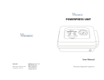
Dimlux maxi controller EVO1 (1.1)
(Datalog)
Contents:
-Introduction
Pag. 2
-Components
Pag. 2-4
-Connecting the lighting
Pag. 4
-Connecting the CO2
Pag. 5
-Connecting aux/fan
Pag. 5
Connecting the VPD
Pag. 5
-Basic/advanced menu
Pag. 6
-Basic keys
Pag. 6
-Basic light
Pag. 7
-Basic CO2
Pag. 7
-Basic aux
pag. 8
-Advanced
Pag. 8
-Advanced keys
Pag. 8
-Advanced light
Pag. 8-11
-Advanced CO2
Pag. 12-14
-Advanced aux
Pag. 15-17
-Advanced VPD
Pag. 17-18
-Advanced high/low log
Pag. 18-19
-Advanced error/alarm log
Pag. 19
-Symbols on the controller
Pag. 19
-Datalog
Pag. 20
1
Introduction
The Dimlux maxi controller is a modular control system for operating and monitoring the Dimlux lighting,
CO2 and VPD. The EVO controller is available with and without USB log function.
The controller also has a thermostat/hygrostat function (AUX) and can also control a fan.
A maximum of 160 Dimlux light fixtures or pre-selector devices can be controlled by means of four
channels. The controller switches the lighting on or off by means of a built-in timer. If a set temperature is
exceeded, the lighting dims automatically or – if necessary – switches off half or all light fixtures off. A
switchboard with timer/relay/reducers is not necessary.
Besides lighting, the controller can also regulate the CO2 level in an air-conditioned room. A very accurate
dual-beam CO2 sensor can be used to control CO2 generators, cold CO2 installations and ventilation
systems for air replacement.
On the AUX port of the EVO 1.1, an “auxbox” can be used to connect a humidifier or a dehumidifier, a
heating system and even a ventilator.
Various parameters can be read and regulated in a VPD environment. The screen shows the ambient
temperature, relative humidity, plant temperature and VPD.
The DATALOG function can be used to store all values on a USB stick. The controller writes all
measured values onto the stick every minute and these can be read off later in graphic form on a PC.
(only EVO 1.1 Datalog version)
The controller can also operate the lighting in two rooms in turns. This requires a second temperature sensor,
which can be connected to port RH/T2. The relative humidity sensor will no longer be required.
The controller is modular: All sensors can be purchased independently according to need.
Components
The controller
The controller regulates and operates the lighting, CO2, VPD status and any other connected components
(AUX).
2
Temperature sensor
The temperature sensor measures the room temperature and should be protected against light
(shaded). A cardboard cover is sufficient.
RH% sensor
The RH% sensor measures the relative humidity in the room. This is necessary to determine the
VPD or to control a humidifier or a dehumidifier. The RH% sensor should also hang in the shade.
CO2 sensor
You can read and control the current CO2 level in a room using a very accurate dual-beam CO2
sensor. The sensor can control a CO2 generator or a cold CO2 installation.
PT camera
The temperature of a crop can be measured using the plant temperature camera. This temperature
provides an indication of the vaporization of the crop. The camera is also needed to determine the
VPD.
3
The auxbox
Auxbox
Auxbox fan
An auxbox can be connected to controller’s aux port. The auxbox converts the maxi controller into
a fully automatic air conditioning system. The auxbox is available in two designs. The auxbox has
two connections, one for a heating system/heater and two for a humidifier or dehumidifier. The
other design can also control a fan as well as a heating system and a humidifier and a dehumidifier.
The fan control is electronic and has no annoying buzz.
Connecting the lighting
The controller communicates with the Dimlux ballasts or the light fixtures by means of a signal
cable, which should be connected between the controller and the various ballasts or light fixtures.
The best signal cable is e.g., a 0.5 mm2 double-core, duo-coloured cable. This is to prevent
connection errors such as mixing up the plus and min core.
A green plug with +1, +2, +3 and +4 indications is located at the side of the controller. These are the
four channels to which up to 40 light fixtures can be connected to each channel. Two min (–)
connections are also available.
The controller is connected with the light fixture/ballast by means of a double-core cable. You select
channel +1 (for example) and a min (–) terminal on the controller. Connect these with the + and –
on the light fixture/ballast. If there is more than one ballast/light fixture, the double-core cable can
be looped in series from the first ballast/light fixture to the next one. Every time + to + and – to – up
to 40 ballasts/light fixtures per channel. If an installation has several light fixtures/ballasts, these
should always be equally divided over two channels. These should preferably be channel +1 and +2.
In the event of a high
temperature protection, channels +2 and +4 break down.A temperature sensor should also be
connected to the controller on the “temp” channel. If this is not done, the temperature protection is
not active and a ‘!’ appears on the display.
4
Connecting the CO2
The dual-beam CO2 sensor can simply be plugged into a wall socket. The long cable including the
plug is inserted into the port with the “CO2” indication.
Now you can connect the CO2 generator or pressure-reducing valve to the CO2 sensor.
Connecting the auxbox
The auxbox is easily connected to an existing wall socket. The long cable is connected to the aux
port via the plug.
Now the components for controlling the box must be inserted into the correct port.
Connecting the VPD
To be able to determine the VPD value, the temperature sensor, RH% sensor and PT camera should
be connected to the controller. Both the temperature sensor and the RH% sensor should be covered
against the incidence of light. A cardboard cover is sufficient.
The PT camera should be mounted in such a way that it “illuminates” the crop under an angle of
approx. 45º without measuring walls, reflectors or other parts of the room as well. A circle with a
diameter of 50 cm is measured if the distance to the crop is 50 cm. The circle is 80 cm if the
distance is 80 cm.
Basic/advanced menu
The controller has a basic and an advanced menu. This enables a very easy operation without the
need to go through the parameters that were set earlier. The basic menu only shows the most
frequently used functions. All parameters can be changed and set in the advanced menu. You can
switch between the basic and the advanced menus by holding down the SET key.
Basic keys
OFF/MODE
By pressing briefly and repeatedly on this key, you can select *Lights permanent off > light always
off.
*Lights permanent on > lights are always on.
*Lights by timer ON/OFF > lights go ON/OFF using the timer.
There are also two shortcut keys available:
When you press the MODE key first and then the MIN (–) key, the “Lights permanent off” starts to
operate immediately. If you press the PLUS (+) key after the MODE key, the “Lights permanent
on” starts to operate immediately.
ESCAPE
By pressing briefly and repeatedly on this key, you can select *LIGHT. The current time, room
temperature, light output and remaining time are displayed.
*CO2. The current and set CO2 value are displayed.
*AUX/FAN The current temperature and the set fan speed are displayed.
*VPD The plant temperature, room temperature, relative humidity and the VPD are displayed.
Using the ESCAPE key will also enable you to leave the menu.
PLUS (+)
You can browse or increase the values by pressing this key briefly and repeatedly.
MIN (-)
You can browse or decrease the values by pressing this key briefly and repeatedly.
SET
Using this key, the menu is opened in order to change settings.
6
Basic light menu
The following parameters can be set in the basic light menu:
*Current time
*Timer ON/OFF
*Type of ballast/light fixture
Time
Press the SET key briefly: the current time will appear. By pressing the SET key again, the time can
be set using the + or – key. Pressing the ESCAPE key will return you to the Home screen.
Timer ON/OFF
Press the SET key shortly and navigate through the menu using the + or – key, until ‘Timer
ON/OFF’ appears on the screen. Pressing the SET key again will allow you to set the ON and OFF
times.
Type of ballast/light fixture
Press the SET key briefly and navigate through the menu using the + or – key, until “output-power”
appears on the screen.
By pressing the SET key again, you can select by using the + or – key which light fixture you wish
to control:
*315 Watt
(CDM lamp)
*400 Watt
(HPS or HPI)
*600 Watt
(HPS/not EL) also called a 230 V lamp
*600 Watt EL UHF
(HPS/EL UHF) also called a 400 V lamp
*630 Watt DUAL
(2 x 315 Watt CDM)
*1000 Watt EL UHF
Also called a 1000 Watt double-ended
Basic CO2 menu
If you press the SET key in the CO2 screen, you can calibrate the sensor automatically. By pressing
the SET key again, you can select Auto Calibrate Yes or No. If you want to calibrate the sensor, it
should be placed in outdoor air for five minutes and then press Auto Calibrate/Yes.
7
Basic aux/fan menu
The following parameters can be set in the basic fan menu:
*Fan mode
*Temperature
Press SET to change these parameters.
Fan mode can be used to choose between the following options:
*Temperature > the fan works faster if a certain temperature is reached.
*Temp day/dehumidify night > the fan works faster if a certain temperature is reached during the
day and during the night if a certain relative humidity is reached.
*Dehumidify day/night > the fan works faster if a certain relative air humidity is reached. Various
values can be set for day and night.
The temperature mode can be used to set the temperature at which the fan must work faster.
Advanced
Numerous parameters can be adjusted or set in the advanced menu.
Advanced keys
OFF/MODE
By pressing briefly and repeatedly on the OFF/MODE key, you can select:
*Lights permanent off >light is always off.
*Lights permanent on >light is always on.
*Lights by timer
>light goes on/off via the timer.
*Lights by countdown >light goes on/off by countdown (asynchronous times, e.g., 10/10 or 11/11)
*Lights control as slave invert > if you use two rooms and two maxi controllers, two or more maxi
controllers can communicate with each other by means of a connection between ports B>B and
C>C on the controllers. A double-core cable should then be placed between these two ports. If
“slave invert” is selected, the light in room 1 (for example) switches off when the light in room 2
goes on and vice versa. The slave controller copies the date, time, timer, countdown and rise/fall of
the master controller.
*Lights control as slave copy > this function is similar to the previous function except that now the
light in room 2 operates at the same time as the light in room 1.
Several controllers using different slave settings can be connected in this manner e.g., 2 “slave
invert” and 3 “slave copy”. If several rooms are used simultaneously, the clock runs the same time
everywhere.
8
ESCAPE
By pressing briefly and repeatedly on this key, you can select *LIGHT. The room temperature, light
output and remaining and current time are displayed.
*CO2 The current and set CO2 value are displayed.
*Aux/fan menu. The set fan speed and temperature/air humidity are displayed
*VPD The plant temperature, room temperature, relative humidity and the VPD are displayed.
*High/low records All high/low values of the connected sensors are displayed here. Using the + and
– keys, the values of the different sensors can be displayed including when the maximum/minimum
event has occurred.
*Events/alarm log Here you can see when and why the controller has intervened.
PLUS (+) key
You can browse or increase the values by pressing this key briefly and repeatedly.
MIN (-) key
You can browse or decrease the values by pressing this key briefly and repeatedly.
SET key
Using this key, the menu is opened in order to change settings.
Advanced light menu
The menu will open by pressing the SET key while the Light screen is displayed. Using the + and –
keys, you can navigate through the various parameters in the menu.
The following parameters can be set in the Light menu:
*Time
The current time can be set by pressing the SET key while TIME is displayed on the screen. For this
purpose, use the + and – keys and confirm with SET.
*Date
The current date can be set by pressing SET if DATE is displayed on the screen . For this purpose,
use the + and – keys and confirm with SET.
9
*Timer ON/OFF
The precise time that the light has to go on or off can be set by pressing the SET key while TIMER
is displayed on the screen. For this purpose, use the + and – keys and confirm with SET.
*Countdown
The time that the light has to go on or off can be set by pressing the SET key while COUNTDOWN
is displayed on the screen. Asynchronous times, which can reduce a cycle can be set with this
parameter.
*Rise/fall
Sunrise and/or sunset can be simulated using rise/fall. The time, which indicates how long the
simulated sunrise or sunset should last can be set by pressing the SET key while Rise/Fall is
displayed.
Temp limit
Three temperatures are displayed: L, H and S. When the first temperature (L = Low-Dim) is
reached, the lights dim to prevent the temperature from becoming too high in the room. The
controller dims the lights up to maximum 35%.
When the second temperature (H = High-Dim) is reached despite the dimmed lights, the controller
switches off all lights operated by the even ports (2 and 4). Half of the lights are therefore turned
off.
When the third temperature (S = Shutdown) is reached despite the fact that all lights are dimmed
and half of the lights are off, all lights go off. Then there is probably a problem with the air
conditioning in the room.
The temperature limits can be altered by pressing the SET key.
-Temp offset
The value of the room temperature sensor can be changed/adjusted or calibrated by pressing the
SET key while TEMP-OFFSET is displayed on the screen. Use the + and - keys for this.Test and
confirm with SET.
10
*Output power
You can select which light fixture/ballast must be controlled by pressing the SET key while
OUTPUT POWER is displayed on the screen. Using the + or – key you can select:
*315 Watt (CDM)
*400 Watt
*600 Watt
*600 Watt EL UHF
*630 Watt DUAL (CDM)
*1000 Watt EL UHF
Select the correct filling/ballast output and confirm with SET.
*Half-force mode
Switching the half-force mode to ON will switch off half of all lights (ports 2 and 4). This might be
required if the ballasts are dimmed but still radiate too much light. It can also be used to prevent
overloading the power supply, when the lights burning in several rooms overlap each other
temporarily. Use the + and – keys and confirm with SET.
*After power failure
In case of a power failure, you can opt for leaving the lights off or for switching the lights back on
after the power supply has been restored. Using the + and – keys, opt for CONTINUE or HOLD
and confirm with SET.
*LCD backlight
By pressing the SET key while LCD backlight is displayed on the screen, you can opt to have the
LCD screen displayed continuously or to switch it on only when a key is pressed. Using the + and keys, opt for always ON or AUTO OFF and confirm with SET.
11
*Temperature display
Here you can select the temperature display in either Celsius or Fahrenheit. Press on the SET key
and using the + and – keys, select Fahrenheit or Celsius and confirm with SET.
*Output display
You can select to display the status of dim/boost in the Light screen in Watt or in percentages. Press
on the SET key and using the + and – keys, select Watt or percentage and confirm with SET.
*Channel control
Up to 40 light fixtures/ballasts can be controlled per port (1, 2, 3 or 4). However, ports 3 and 4 can
also be used to control a second room including lighting using the “slave invert” function with a
maximum of 80 light fixtures per room. Channels 3 and 4 will then switch ON when Channels 1
and 2 switch OFF and vice versa. In addition, an optional SSR relay can be controlled in order to
connect another type of lighting together with the Dimlux light fixtures/ballasts. By pressing the
SET key and using the + and – keys, you can select:
- Normal > ports 1, 2, 3 and 4 control all ballasts/light fixtures.
- Channels 3 & 4 invert > ports 3 and 4 operate contrary to ports 1 and 2. The second temperature
sensor that can be connected on the RH/T2 port can be used to control two rooms operating in turns.
The RH function is then not necessary.
- Channels 3 & 4 relay > ports 3 and 4 control an SS relay with which another type of lamp can be
connected.
Advanced CO2 menu
Press briefly on the SET key in the CO2 display screen to open the CO2 menu. Use the + and - keys
to navigate through this menu.
*Auto calibrate
The auto calibrate function sets the value automatically to 400 ppm if the sensor is located in
outdoor air. Put the sensor for five minutes in outdoor air, press on the SET key and select auto.
Calibrate Yes or No and confirm with SET.
12
*Manual calibrate;
You can also select to calibrate the sensor manually.
Pressing briefly on the SET key will open the menu. Press the SET key once more when CO2
calibrate is displayed.
Here you can adjust the value. If the sensor indicates 440 ppm for example in outdoor air, you
calibrate the sensor by filling in –40 ppm using the + and – keys.
*CO2 mode
You can opt to add or remove CO2 (air quality in living accommodation).
CO2 Addition is selected if CO2 needs to be added.
CO2 Removal is selected if CO2 needs to be removed.
*CO2 smartlogic
If the CO2 smartlogic function is on, a special algorithm is used to keep the CO2 value as stable as
possible.
If this function is off, the controller doses CO2 until the set value is reached.
*Start dosing time
To deal with gas/CO2 more efficiently, you can opt for dosing the CO2 after the lights come on. By
pressing the SET key and using the + and – keys, you can select the interval in minutes between
lights on and dosing of CO2.
*Stop dosing time
To deal with gas/CO2 more efficiently, you can opt for stopping the CO2 dosing before the lights go
off. You can select the interval in minutes between stopping the CO2 dosing and lights off by
pressing the SET key.
13
*CO2 dose time
The heater must burn for at least four seconds to guarantee complete burning of the gas when using
a CO2 generator. In practice, you might observe that the gas does not burn well below this
minimum value. In that case, the generator switches on/off (oscillates) quickly, possibly resulting in
the release of toxic gases.
The minimum dose period can be changed by pressing the SET key. The dose period can be set to a
minimum in case of using cold CO2. For heaters, we advise:
up to 10 m2: 6 sec.
10-16 m2: 12sec.
16-24 m2: 18sec.
over 24 m2: 24sec.
*CO2 night heater
A room can also be heated by the CO2 generator if the power supply is limited. The night
temperature can be set by pressing the SET key.
Attention!
Ensure sufficient supply of fresh air to the room. Poor burning can cause the release of toxic gases
that are harmful to people, animals and plants. The flame must always burn with a blue colour.
14
Advanced aux/fan menu
Eight parameters can be set in the advanced fan menu in order to ensure that the installation works
as efficiently as possible.
*Temperature
*RH Day
*RH Night
*Max fan speed Day
*Max fan speed Night
*Min fan speed
*The aux setting Heat
*The aux setting RH
Press SET once and use the + and- keys to select the above options.
Press SET once more to change these parameters.
The fan mode can be changed by pressing the SET key twice. The fan mode determines when the
fan control becomes active. It is possible to choose between the following options:
*Temperature > the fan works faster if a preset temperature is reached.
*Temp day/dehumidify night > the fan works faster if a preset temperature is reached during the day
and during the night if a preset relative humidity is reached.
*Dehumidify day/night > the fan works faster if a preset relative humidity is reached. A different
value can be set for the day than for the night.
*Manual > the fan is set manually to a set speed.
*The temperature mode can be used to set the temperature at which the fan must work faster.
*The RH day mode can be used to set the maximum humidity during the day.
*The RH night mode can be used to set the maximum humidity during the night.
*Max speed day can be used to set the maximum fan speed during the day.
*Max speed night can be used to set the maximum fan speed during the night.
*The min speed mode can be used to set the minimum fan speed.
(Some fans or ventilators cannot be dimmed by more than 30%). Always check for a draught and
whether the fan is working.
*The aux settings for temperature
*The aux settings for relative air humidity
15
The two aux settings can be used to control the heating systems and the humidifiers and
dehumidifiers.
The menu structure is as follows:
Pre-heat
The pre-heat function enables you to pre-heat a room before the lights come on. This is useful for
preventing problems relating to condensation, etc.
Night heater
The pre-heat function enables you to control a heater when the lights are off.
16
*RH% (AUX)
Using an optional aux box, the controller can humidify or dehumidify during the periods lights on
and lights off or always.
The menu structure is as follows:
Therefore, you can opt for humidifying or dehumidifying during the periods lights on and lights off
or both.
Advanced VPD menu
You can read the room temperature (AT), relative humidity (RH%), plant temperature (PT), delta-T
(DT) and the VPD value on the VPD display screen. You can switch between PT and DT by
pressing the + and – keys in this screen. PT is the plant temperature measured with the plant
temperature camera. Delta-T indicates the difference between AT and PT.
The difference between plant temperature and room temperature provides an indication of whether
a plant vaporizes or not. VPD provides an indication about the vaporization pressure. A crop that
vaporizes normally is ca. 2 degrees cooler than the room temperature. The vaporization pressure
(VPD) is usually between 0.6 and 1.5 kPa.
Pressing the SET key on the VPD display screen will open the menu.
*PT>AT Dim
The crop does not vaporize adequately if the plant temperature is higher than the room temperature.
The controller can intervene by dimming the lights and turning off the CO2 dosing. The difference
in temperature can be set by pressing briefly on the SET key and using the + and – keys to fill in a
value. A typical value is – for example, +2 degrees. The controller will intervene if the leaves of the
crop are 2 degrees warmer than the room.
17
*PT>AT shutdown
The plant temperature will increase further if the controller has intervened but no measures are
taken to restart the vaporization. The controller will then shut down the lights completely if the
plant temperature rises. The difference in temperature in which the controller shuts down all lights
can be set in the PT>AT shutdown option. A typical value in which the controller does this is
usually +2 degrees higher than in PT>AT Dim (therefore +4 degrees).
*PT offset
Here you can adjust any deviation in the display of the temperature measured by the plant
temperature (PT) camera.
Since the controller intervenes in case of relatively small temperature differences, it is important
that the room temperature indicates the same value as the plant temperature camera. You can check
whether the values correspond by hanging a sheet of paper in the shade of the room. You can check
whether there is a difference in the room temperature and the PT camera by directing the PT camera
toward the sheet of paper after approx. 20 minutes. (The sheet of paper adopts the temperature of
the room).
You can adjust the value by pressing briefly on the SET key and using the + and – keys.
*RH offset
The sensor that measures the RH% in the room can also be calibrated. Press the SET key and use
the + and – keys to adjust the value.
High/low
Here all high/low values of all connected sensors are displayed. By using the + and - keys, the
values of the different sensors can be displayed including when the maximum/minimum event has
occurred.
*AT high/low
The highest and lowest room temperature including the time are displayed.
18
*RH% high/low
The highest and lowest RH% value including the time are displayed.
*PT high/low
The highest and lowest plant temperature including the time are displayed.
*CO2 high/low
The highest and lowest CO2 value including the time are displayed.
The high/low values can be reset by pressing the SET key in this screen and by using the + and –
keys to select Reset > Yes.
The high/low values are overwritten every 24 hours!
Error/Events
The error/events screen shows the date and time that an event or error has occurred. Here you can
read (for example) whether dimming was carried out, because the temperature was exceeded.
The log can store up to 10 events/errors. If the log is full, the first entry is overwritten.
Pressing the SET key will erase the event/error log.
If the message PSU ..... V ! ! ! appears, the controller is connected to an adapter with the incorrect
voltage. The voltage must be 16 volts. Use the original adapter.
Symbols on the controller
Main screen (light)
'!' = sensor not present
CO2 screen
*' = CO2 dosing or heating
' ' = normal off
X' = CO2 Off due lamps off
' ' = normal on
'!' = CO2 sensor not present
'L' = low dim temp control
'J' = Co2 sensor jammed
'H' = high dim temp control
'P' = Co2 off due PT
'S' = shut down-overheat
' ' = CO2 normal off
'P' = Temp control PT plant temperature
'1' = (MH4) gas alarm (fire-toxic)
'X' = Shut down-overheat PT plant temperature
'2' = (CO) carbon monoxide alarm (toxic)
19
DATALOG (only EVO 1.1 datalog)
The EVO DATALOG can be used together with a USB data stick to store all values measured by the controller in order
to view these later in graphic form on a PC. The controller writes the values onto the stick every minute.
Press the OFF/MODE key for four seconds to start the log. The message “initializing USB stick” appears on the screen.
The 400 Watt lamp flashes once a minute to indicate that data are being written to the disk. Press the OFF/MODE key
once more for four seconds to stop the log. The message “stop logger” appears on the screen.
If the message “Fatal USB error” appears on the screen, the stick provided is probably not being sued or the stick must
be formatted.
LED indication on Dimlux ballasts.
The ballast of Dimlux has its own self - diagnosis system. Using a red and green LED on the ballast or fixture
An error or the status can be read.
On = LED on
Off = LED off
Strobo = very fast flash
Flash = normal blink
Meaning abbreviations
Off- DB = lamp off by dimmer switch
On- DB = Lamp on by dimmer switch
Off = Brake Lamp off by maxi controller
On = Brake Lamp on by maxi controller
Open = Open contact
20
SHORT= Short circuit or defective lamp
HTP = High temperature protection active
HVP = Too high voltage (power supply )
LVP = Low voltage ( power supply)
EOL = End Off Life (lamp)