1
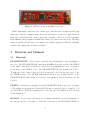
To control our robot, we utilized a powerful 32 bit microprocessor, the PIC32MX795F512L
which allows us to perform complex calculations in real time [2]. This allows the robot
to perform complex computer vision tasks and control algorithms. With the PIC32 as
the foundation I built the firmware for the robot, implementing the fundamental sensory
and motor controls of the humanoid robot. The first step was to implement the necessary
communication protocols to connect the PIC32 with the other software components: I2C
to integrate other integrated circuit chips, USB to communicate with the PC, and UART
to communicate with other controllers. These systems cover nearly the full spectrum of
communication protocols used by common ICs and components used for embedded software
and robotics applications, and they allow us to easily integrate new components and features
into the robot hardware.
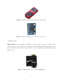
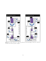
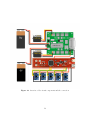
The motor functions of the robot are mainly governed by a collection of servos on the arms
and legs. To control the servos, I utilized the SSC-32 servo controller, a powerful controller
capable of synchronizing the motions of 32 servos at the same time [3]. A single SSC-32,
controlled through a serial UART connection, would be able to control the motions of the
arm and legs and synchronize them with millisecond precision. The sensory information
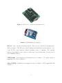
consists of accelerometer and gyro readings from the MPU6050. The MPU6050 is connected
through an I2C connection, and it consists of a 3-axis gyro and a 3-axis accelerometer, as
well as temperature sensors. The MPU6050 can also be connected to other sensors such as
magnetometers [4]. The MPU6050 can be placed on the arms and legs to generate sensory
feedback for controlling the motions of the legs and arms.
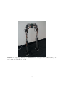
The team completed the bipedal legs of the robot, and I was able to test the controller on
the bipedal system. The control of walking was based on a linear combination of different
sine waves which governed the periodic motion of the legs. Through system testing, we
discovered that the robot has very high power requirements, and the power supplies we had
could not power the entire system. Much more powerful power supplies will be needed to
complete full system tests. The report describes the detailed design of the firmware and the
robotic legs on which the firmware was tested, as well as the challenges we faced and our
recommendations to the sponsor for moving forward with the project.
3