1
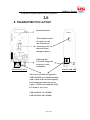
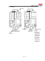
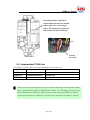
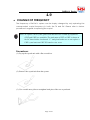
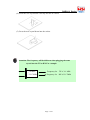
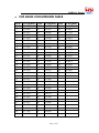
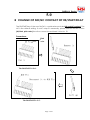
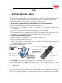
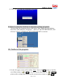
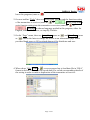
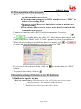
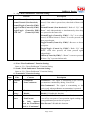
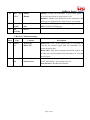
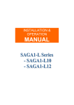
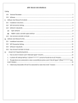
SAGA1-L Series
INSTALLATION &
OPERATION
MANUAL
Page: 1/23
SAGA1-L Series
PREFACE
This installation & operation manual is intended as an
instruction manual for trained person who is in charge
of installation, maintenance, repair, etc.
Before installation please read the user’s guide and this
installation & operation manual carefully.
Page: 2/23
SAGA1-L Series
The main contents of this manual are organized into the following chapters.
Table of Contents
PREFACE
1.0 Wire Diagram of SAGA1-L series………………………………………….....p.4
2.0 Transmitter PCB Layout………………………………………………………..p.5
3.0 Receiver PCB Layout…………………………………………………………..P.6
3-1 Relay Board for SAGA1-L8, L6, L4, L8B, L6B
3-2 Independent COM Line
3-3 Receiver/Decoder Board for SAGA1-L8, L6, L4, L8B, L6B
4.0 Change of Frequency…………………………………………………………P.10
5.0 Change of NO/NC Contact of R0/START Relay..…………………………P.14
6.0 ID-Code Remote Setting ………………………………………………………P.15
7.0 Troubleshooting………………………………………………………………….P.16
Appendix
SAGA1-L Series Software Installation And Operation Instruction…………P.17~23
Page: 3/23
SAGA1-L Series
1.0
z
WIRE DIAGRAM OF SAGA1-L SERIES:
SAGA1-L8, L8B
SAGA1-L6
(2)
(4)
(1)
SAGA1-L4
SAGA1-L6B
(3)
Note: The polarity direction for
Remark: (1) The R0/START could be N.C. or N.O.
the power of DC12/24V
(2) The fuse for the power AC24/48/110/220/380V is 0.5A.
isn’t required when
The fuse for the power DC12/24V is 1.5A.
plugging in the power
(3) The fuse for AC type at the COM(MAIN) is 10A.
line connector.
The fuse for DC type at the COM(MAIN) is 20A.
(4) The com lines have been arranged prior to shipment, if an independent
Page: 4/23
SAGA1-L Series
COM line is required, please refer to page:8/23.
2.0
z TRANSMITTER PCB LAYOUT:
Internal Antenna
This terminal is used
for copier to read
and write data or
connecting to PC for
function setting
through software.
Replacing this
Crystal to change the
frequency on the
transmitter.
SAGA1-L4, L6, L8
SAGA1-L6B, L8B
There are two kinds of frequencies
VHF and UHF are available marking
with a check is the current frequency
band and please make sure not to
replace a VHF crystal unit into UHF
PC board or visa versa.
VHF:310.0325~331.165MHz
UHF:425.5925~446.725MHz
Page: 5/23
SAGA1-L Series
3.0
z RECEIVER PCB DIAGRAM:
3-1. Relay Board for SAGA1-L8, L6, L4, L8B, L6B
3-1-1 DC Type
Fuse: 20A
(yellow color)
Fuse: 1.5A
DC Input
Remark: The polarity direction of DC Input isn’t required
when plugging in the power line connector.
Page: 6/23
SAGA1-L Series
3-1-2 AC Type
Fuse: 10A
Fuse: 0.5A
SAGA1-L8, L8B, L6B
SAGA1-L6
AC Input
Page: 7/23
Voltage selection
Jumper:
HI position to
select higher
voltage of the
combination,
LO position to
select lower
voltage of the
combination.
SAGA1-L Series
If an independent COM line is
required then cut the wire labeled
with a white “X” as showing as
below. The longer part of the wire
will become the new COM Line.
Cut the
wire here.
SAGA1-L4
3-2. Independent COM Line:
The SAGA1-L series offer optional independent COM lines as:
SAGA1-L8/L8B 4 independent COM lines
Up/Down, East/West, South/North and R0
SAGA1-L6
3 independent COM lines
Up/Down, East/West, R0
SAGA1-L4
2 independent COM lines
Up/Down, R0
SAGA1-L6B
1 independent COM line
Up/Down ~East/West 2S and R0
Please refer to the above figures of receiver relay boards and if an independent COM
line is required then cut the wire labeled with a white “X”. The longer part of the wire
will become the new COM Line. Then you may connect this new COM wire with an
existed spare output wire, otherwise, you have to use an extra wire made by yourself.
Page: 8/23
SAGA1-L Series
3-3. Receiver/Decoder Board for SAGA1-L8, L6, L4, L8B, L6B
Replacing this
There are two kinds of
Crystal to Change
the frequency on
the receiver.
SQ ADJ is used for
a minimum receiving
sensitivity adjustment,
please don’t adjust
arbitrarily.
If necessary, adjusting
clock wise (allow
receiving a weaker
signal) until the SQ
lamp turns on, then
adjusting counter
clock wise (allow
receiving a stronger
signal) until the SQ
lamp turns off to keep
the SQ lamp at “off”
status before
The SQ lamp will turn on
operating.
when receiving any radio
signal. It was taken as
interference if the SQ
lamp didn’t at “off” status
before operating.
The receiving sensitivity
is adjustable via the SQ
ADJ.
Page: 9/23
frequencies VHF and UHF
are available marking with a
check is the current
frequency band and please
make sure not to replace a
VHF crystal unit into UHF
PC board or visa versa.
VHF:310.325~331.165MHz
UHF:425.5925~446.725MH
This terminal is used for
copier to read and write
data or connecting to PC
for function setting.
through software.
The RX memory is
defective if the Error
LED flashes red every
0.5 second slowly.
SAGA1-L Series
4.0
z
CHANGE OF FREQUENCY
The frequency of SAGA1-L system can be simply changed by only replacing the
correspondent crystal frequency in both the TX and RX. Please refer to below
procedure in regards to replacing the crystal.
Note: To replace a new crystal, please note that there are 2 kinds of frequencies
(VHF and UHF) are available. The indication of VHF or UHF is shown on
the PC board with a check mark “V” and please make sure to not replace a
VHF crystal unit into UHF PC board or visa versa.
Procedures:
(1). Pry up the crystal unit with a flat screwdriver
(2). Remove the crystal unit from the system.
(3). Use a needle nose pliers to straighten both pins of the new crystal unit.
Page: 10/23
SAGA1-L Series
(4). Insert the new crystal unit vertically into the PC board.
(5). Press the new crystal down into the socket.
Attention: The frequency will be different when plugging the same
crystal into the TX or RX. For example:
T:311MHz
R:321.7MHz
Frequency for TX is 311 MHz
Frequency for RX is 321.7MHz
Page: 11/23
SAGA1-L Series
VHF BAND CONVERSION TABLE
z
CH No. Ch-Freq(MHz) CH No. Ch-Freq(MHz) CH No. Ch-Freq(MHz)
1
310.0325
32
318.3250
63
326.6175
2
310.3000
33
318.5925
64
326.8850
3
310.5675
34
318.8600
65
327.1525
4
310.8350
35
319.1275
66
327.4200
5
311.1025
36
319.3950
67
327.6875
6
311.3700
37
319.6625
68
327.9550
7
311.6375
38
319.9300
69
328.2225
8
311.9050
39
320.1975
70
328.4900
9
312.1725
40
320.4650
71
328.7575
10
312.4400
41
320.7325
72
329.0250
11
312.7075
42
321.0000
73
329.2925
12
312.9750
43
321.2675
74
329.5600
13
313.2425
44
321.5350
75
329.8275
14
313.5100
45
321.8025
76
330.0950
15
313.7775
46
322.0700
77
330.3625
16
314.0450
47
322.3375
78
330.6300
17
314.3125
48
322.6050
79
330.8975
18
314.5800
49
322.8725
80
331.1650
19
314.8475
50
323.1400
20
315.1150
51
323.4075
21
315.3825
52
323.6750
22
315.6500
53
323.9425
23
315.9175
54
324.2100
24
316.1850
55
324.4775
25
316.4525
56
324.7450
26
316.7200
57
325.0125
27
316.9875
58
325.2800
28
317.2550
59
325.5475
29
317.5225
60
325.8150
30
317.7900
61
326.0825
31
318.0575
62
326.3500
Page: 12/23
SAGA1-L Series
z
UHF BAND CONVERSION TABLE
CH No. Ch-Freq(MHz) CH No. Ch-Freq(MHz) CH No. Ch-Freq(MHz)
101
425.5925
132
433.8850
163
442.1775
102
425,8600
133
434.1525
164
442.4450
103
426,1275
134
434.4200
165
442.7125
104
426.3950
135
434.6875
166
442.9800
105
426.6625
136
434.9550
167
443.2475
106
426.9300
137
435.225
168
443.5150
107
427.1975
138
435.4900
169
443.7825
108
427.4650
139
435.7575
170
444.0500
109
427.7325
140
436.0250
171
444.3175
110
428.000
141
436.2925
172
444.5850
111
428.2675
142
436.5600
173
444.8525
112
428.5350
143
436.8275
174
445.1200
113
428.8025
144
437.0950
175
445.3875
114
429.0700
145
437.3625
176
445.6550
115
429.3375
146
437.6300
177
445.9225
116
429.6050
147
437.8975
178
446.1900
117
429.8725
148
438.1650
179
446.4575
118
430.1400
149
438.4325
180
446.7250
119
430.4075
150
438.7000
120
430.6750
151
438.9675
121
430.9425
152
439.2350
122
431.2100
153
439.5025
123
431.4775
154
439.7700
124
431.7450
155
440.0375
125
432.0125
156
440.3050
126
432.2800
157
440.5725
127
432.5475
158
440.8400
128
432.8150
159
441.1075
129
433.0825
160
441.3750
130
433.3500
161
441.6425
131
433.6175
162
441.9100
Page: 13/23
SAGA1-L Series
5.0
z CHANGE OF NO/NC CONTACT OF R0/START RELAY
The R0/START key of the new SAGA1-L crystal series provides NO and NC contact. The
NO is the default setting. If a NC output is necessary, please remove the No. 8 wire
(R0/Start, pink color) from the connector and insert it into No. 10.
Procedures:
Pink
color
The R0/START is N.O.
The R0/START is N.C.
Page: 14/23
SAGA1-L Series
6.0
z
ID-Code Remote Setting
ID-Code remote setting allows you to pair the new TX or RX if one of them is damaged.
In order to work the TX & RX must have the same frequency. Using ID-Code remote
setting will make both the TX and RX to have the same ID Code.
1). Please make sure the following conditions before ID-Code remote setting:
(a) Both TX and RX are of the SAME model and frequency.
(b) To place the transmitter as close as possible to the receiver to avoid any
interference.
(c) Turn off the RX power more than 10 seconds and turn it on again.
(d) Complete the ID-Code remote setting within 4 minutes after turning on the RX. The
RX will NOT accept the ID-Code remote setting signal after 4 minutes.
2). ID-Code remote setting Instructions:
(a) Press and hold the transmitter STOP pushbutton/EMS button.
(b) Press DOWN pushbutton and hold it.
(c) Press UP pushbutton 4 times and release “STOP & DOWN” pushbuttons when the
red light on the transmitter is flashing.
(d) Start the system as usual.
Press EMS button
Press and hold
the STOP
Continuing press the
UP pushbutton for 4
Continuing press
the UP pushbutton
for 4 times
Note: For SAGA1-L6B
times
Press and hold the
DOWN pushbutton
Press and hold the
DOWN pushbutton
1. The DOWN pushbutton must be remaining in 1st step while holding the button.
2. Press UP pushbutton till 1st step continuing for 4 times. Do not press button into 2nd step
while processing this instruction otherwise the ID-Code remote setting will be aborted.
z ATTENTION:
* In case ID-Code remote setting fails, repeat the instructions above within 4 minutes.
* ID-Code remote setting is available for ID Code only. It will not change function settings
* Within the operating distance, all same model systems on the same frequency will be
paired with the transmitters ID Code.
Page: 15/23
SAGA1-L Series
7.0
z
TROUBLESHOOTING
Item Phenomenon
1
Red LED flashing quickly
(every 0.2 sec.) when
Cause
a) One of the pushbutton a) Replace the
is jammed.
any motion pushbutton of b) The system is not
Transmitter is pressed.
Action Required
pushbutton.
b) Power on
properly powered
again according
according to the
to the instruction.
instruction.
2
TX LED flashes red and
The memory of the TX is
Send back the
yellow reciprocally and
defective.
Manufacturer.
RX Error LED flashes red
The memory of the RX is
Send back the
slowly (every 0.5 sec.)
defective.
Manufacturer.
The operating distance
It was interfered by other Replace the crystal
slowly (every 0.5 sec.)
3
4
Is shorter or an intermittent Radio Remote Controller of both TX and RX
operation is happened.
/or unknowing signal with to change the
the same frequency.
frequency.
Remark: The memory of the TX and RX has Anti-copy function design, any
inadequate action on decoding the firmware of the memory will cause
the trouble as the above item 2 and 4.
If any problem couldn’t be solved or any comments, suggestions please fax
to 886-7-8157253
Gain Electronic Co., Ltd.
01/2004 v.1.0
Page: 16/23
SAGA1-L Series
Appendix
SAGA1-L Series Software Installation and
Operation Instruction
I. How to install the SAGA1-L function setting program:
1. Insert the CD-ROM into the CD-ROM driver, the program initiates
automatically, then you see a screen as below, click “OK” and continue:
2. The next screen you see is as below, click on
or “Change Directory” if
you intend to install the program in other directory than the preset drive.
3. Click on “Continue” to proceed with the installation.
Page: 17/23
SAGA1-L Series
4. Click “OK” to finish the installation procedure.
II. How to start the SAGA1-L function setting program:
To start using this program, please click from “Start” menu on your desktop,
then move your mouse to “Programs”, “SAGA1-L SETUP PROGRAM”, and
click on “saga1-L (CRYSTAL) SETUP PROGRAM” to activate.
III. Toolbar of the program:
1. On the left upper corner of the toolbar “File”, there are Load means to load the
saved data (same as
); Save to save the current data (same as
); Printer to
print out the existing data shown on the current screen (same as
); Exit to
Page: 18/23
SAGA1-L Series
leave this program (same as
).
2. On next toolbar “Tools” there are Read Setup Data to read the function setting
of the transmitter or receiver (same as
or
); Write Setup Data to
write function setting into the transmitter or receiver (same as
or
); Language to choose language applied in this program, either for
English, traditional Chinese, or simplify Chinese.
3. On the “Page” menu, there are Setup-Page (same as
) and User-Page (same
as
), choose the latter to change the screen to an information page which
provides blank space to fill in related datum of the distributor and user.
4. When chose “File” Load or
, a screen popped up to load data file in “DSA”
format as below. The use of this saved data is to record corresponding details of
the setting in order to make a duplication of the transmitter or receiver.
Page: 19/23
SAGA1-L Series
IV. The operation of the program:
Note: a. Make sure the power is off before any reading or writing either
on the transmitter or receiver.
b. Check the connection port on RS232 whether it is on “COM1” or
others if the reading failed.
c. Do aware to read first every time before writing or making any
function setting.
d. This software allows user to read or write directly from both the
transmitter and receiver.
1. Connect the interface cable (RS232) with the transmitter of receiver.
2. When the computer is connected with the transmitter or receiver, click on
to read the data, then click “OK” after the new data is input, and
or
a new screen with “Model” and “ID-Code” appeared as below (lower picture).
or
3. When the new settings or modification have been made, click
to write data into the transmitter or receiver, then click “YES”.
3. If you want to save the new setting, click on
format.
.
4. To print out the setting, click on
to save the data with “DSA”
V. Function setting of SAGA1-L by PC Software
Definition for special terms:
*ID-Code Remote Setting : When the power is on, the ID-Code of the receiver can be
changed remotely by the transmitter within 4 minutes.
*Power Saving: The signal is sent by the transmitter periodically to save power, the effective
distance will be lessened once this mode is chosen.
Page: 20/23
SAGA1-L Series
1. “Start Key” Function Setting
Item
A
B.
Title
Content
This function is available only when remote controller is
“Power-On”.
Normal
Toggle
Description
1. Control by EMS
2. Bypass EMS
“Normal”: “R0” relay is on when “Start/R0” pushbutton
is pressed or rotary key switch (for L6B, L8B) turned to
“START” position; ”R0” relay is “off” when pushbutton is
released or rotary key is re-turned to “ON” position.
“Toggle”: Same as “Normal” to activate “R0” relay. But
“R0” relay is on once activated, off when pushbutton is
pressed or key is turned to “START” again.
PS: When it is “Toggle”, choose “Control by EMS” or
“Bypass EMS”.
2. “R/C” Function Setting:
Item
A
B
Title
ID-Code
Remote
Setting *
Content
1. Enable
2. Disable
Description
“Enable”: Allows user to change ID-Code by Remote
Control method.
“Disable”: Disable this function.
“Any-Pushbutton”: To activate the main relay on (power
Power On 1. Any-Pushbutton
on) with any pushbutton.
Mode
2.
Start-Pushbutton/Key “Start-Pushbutton/Key”: To activate the main relay on
(power on) by rotate the “Start Key” or press “Start/R0”
button only.
Page: 21/23
SAGA1-L Series
3. “Up / Down Pushbutton” Function Setting:
Item
Content
Description
A
Normal/Normal (Interlock)
Normal/Normal (Non-Interlock)
Normal/Toggle (Control by EMS)
Toggle/Normal (Control by EMS)
Toggle/Toggle (Control by EMS)
Off /On
(Control by EMS)
“Normal/Normal (Interlock)”: When “Up” or “Down” is
pressed, if the other is pressed too, then both of them will
be off.
“Normal/Normal (Non-Interlock)”: Both of “Up” and
“Down” work independently or simultaneously when they
were pressed at the same time.
“Normal/Toggle (Control by EMS)”: “Up” is on when
pressed, off when released; “Down” is on once pressed, off
when pressed again.
“Toggle/Normal (Control by EMS)”: Reverse to above
description.
“Toggle/Toggle (Control by EMS)”: Both “Up” and
“Down” work once pressed, off when pressed again
independently.
“Off/On (Control by EMS)”: “Down” is on once pressed,
off when “Up” is pressed afterwards.
4. “East / West Pushbutton” Function Setting:
Same as “Up / Down Pushbutton” Function Setting
5.“South / North Pushbutton” Function Setting:
Same as “Up / Down Pushbutton” Function Setting
6.“Transmitter” Function Setting:
item
A
Title
Transmit
Mode
Content
1. Continuous
2. Non-Continuous
Description
“Continuous”: The signal is transmitting to the receiver
by transmitter continuously during “Power-On”.
“Non-Continuous”: The signal is transmitting to the
receiver only when pushbutton on transmitter is pressed.
“Enable”: Enable the “power saving mode”.
“Disable”: Disable this function.
B
Power
saving *
1. Enable
2. Disable
C.
SavePower
“1 min~30 min”: Choose the due time for the transmitter
1. 1 min~30 min
to cut off its own power if no operation signal sending out
2. Non-Execute
PS. Only appears by any pushbutton pressed to save power.
when the Transmitter “Non-Execute”: Disable this function.
Mode is “Continuous”
Page: 22/23
D.
Auto Off 1. Enable
(Tx)
2. Disable
SAGA1-L Series
“Enable”: Enable the transmitter to send EMS signal to
the receiver too before its own power is off.
“Disable”: Disable this function but the transmitter still
will be power off itself if the “Save-Power” is executed.
E.
Led
On/Off
1. On
2. Off
“On”: Enable LED lights on while operating.
“Off”: Disable LED lights on.
F.
Led
Off-Time
0~4.0 sec
Determine the interval of LED shining time.
7.“Receiver” Function Setting:
Item
A
Title
Passive
Act
Content
1. Power-Off
2. Relay-Off
Description
“Power-Off”: The “Power”(main relay) is off when not
receiving any normal signal from the transmitter for a
certain period of time.
“Relay-Off”: Only those operating functional replays are
off when not receiving signal from transmitter for a certain
period of time.
B
Auto
(Rx)
Off 1. 10 min~4 hour
2. Non-Execute
“10min~4hour”: Choose the due time for the receiver to
cut off “Main Relay” if no signal received.
“Non-Execute”: Disable this function.
Page: 23/23