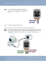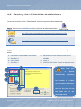
1
I-7560U/7561U/7563U User Manual U USSBB ttoo RRSS--223322//442222//448855 CCoonnvveerrtteerrss VVeerr.. 11..00,, DDeecc.. 22001133 WARRANTY All products manufactured by ICP DAS are warranted against defective materials for a period of one year from the date of delivery to the original purchaser. WARNING ICP DAS assumes no liability for damages consequent to the use of this product. ICP DAS reserves the right to change this manual at any time without notice. The information furnished by ICP DAS is believed to be accurate and reliable. However, no responsibility is assumed by ICP DAS for its use, nor for any infringements of patents or other rights of third parties resulting from its use. COPYRIGHT Copyright © 2013 by ICP DAS. All rights are reserved. TRADEMARKS Names are used for identification purposes only and may be registered trademarks of their respective companies. CONTACT US If you have any questions, please feel to contact us at: [email protected] ; [email protected] We will give you quick response within 2 workdays. USB to RS-232/422/485 Converters TABLE OF CONTENTS Chapter 1 1.1 1.2 Introduction ................................................................................................................... 4 Overview ............................................................................................................................ 5 Features............................................................................................................................ 7 1.3 Chapter 2 2.1 Applications........................................................................................................................ 7 Hardware Information................................................................................................ 9 Front and Back View ........................................................................................................ 10 2.1.1 I-7560U........................................................................................................................ 10 2.1.2 I-7561U and I-7563U ................................................................................................... 11 2.2 Specifications ................................................................................................................... 13 2.2.1 I-7560U Specifications ......................................................................................... 13 2.2.2 I-7561U Specifications ......................................................................................... 14 2.2.3 I-7563U Specifications ......................................................................................... 15 2.3 2.4 JP3: Output Type Selection (I-7561U Only) ...................................................................... 16 Pin Assignments ............................................................................................................... 18 2.4.1 I-7560U................................................................................................................. 18 2.4.2 I-7561U................................................................................................................. 18 2.4.3 I-7653U ................................................................................................................. 19 2.5 Wiring Notes .................................................................................................................... 20 2.5.1 RS-232 .................................................................................................................. 20 2.5.2 RS-422 .................................................................................................................. 21 2.5.3 RS-485 .................................................................................................................. 21 2.6 Internal I/O Structure ....................................................................................................... 22 2.6.1 I-7560U................................................................................................................. 22 2.6.2 I-7561U................................................................................................................. 23 2.6.3 I-7563U................................................................................................................. 24 2.7 Dimensions....................................................................................................................... 25 2.7.1 I-7560U................................................................................................................. 25 2.7.2 I-7561U and I-7563U ............................................................................................ 26 Chapter 3 Software Installation .............................................................................................. 27 3.1 Obtaining the Driver Installer Package............................................................................. 28 3.2 3.3 Installing the I-756xU Series Drivers ................................................................................ 29 PnP Driver Installation...................................................................................................... 33 ICP DAS CO., LTD. User Manual/ Ver. 1.0/ Dec. 2013/ Page: 2 USB to RS-232/422/485 Converters 3.4 Verifying the Installation .................................................................................................. 35 3.4.1 How do I get into Windows Device Manager? ........................................................... 35 3.4.2 Check that the Configuration of the COM Port........................................................... 37 3.5 Uninstalling the Device Driver.......................................................................................... 38 Chapter 4 Manual Testing ....................................................................................................... 39 4.1 Self-Test Wiring ................................................................................................................ 40 4.1.1 I-7560U (RS-232 Wiring) ...................................................................................... 40 4.1.2 I-7561U (RS-232 Wiring) ...................................................................................... 40 4.1.3 I-7563U (RS-485 Wiring) ...................................................................................... 41 4.2 Testing the I-756xU Series Modules ................................................................................. 42 ICP DAS CO., LTD. User Manual/ Ver. 1.0/ Dec. 2013/ Page: 3 USB to RS-232/422/485 Converters Chapter 1 Introduction The following is a brief overview of the I-756xU series modules, including the features and applications. ICP DAS CO., LTD. User Manual/ Ver. 1.0/ Dec. 2013/ Page: 4 USB to RS-232/422/485 Converters 1.1 Overview What is USB? The Universal Serial Bus (USB) is an industry standard connectivity specification developed by computer and telecommunication industry members and is used to attach external peripherals to computers. USB was designed to standardize the connection of peripherals and eliminate the need to open the computer case in order to install additional interfaces needed for certain devices. USB is designed to meet the Microsoft Plug and Play (PnP) specifications, meaning that users can install and hot-swap external devices without requiring lengthy installation procedures and reducing the need to reboot the computer. The I-756xU USB to RS-232, RS-485 or RS-422 converter is a smart and convenient accessory that allows RS-232/RS-422/485 serial devices to be connected to a USB-equipped Windows or Linux host computer. The I-756xU provides a bridge connection that includes a standard DB 9-pin male serial port connector at one end and a standard Type-A USB plug connector at the other. Simply attach the serial device to the serial port on the cable and insert the USB connector into the USB port on the PC. This provides a convenient method of adding serial connections to the PC without having to install an additional serial card or perform the necessary configuration associated with a traditional port connection. This USB to Serial adapter is ideal for connecting modems, cellular phones, PDAs, digital cameras, card readers and other serial devices to your computer. It provides serial connections up to 1 Mbps of data transfer rate. And since USB does not require any IRQ resource, more devices can be attached to the system without the previous hassles of device and resource conflicts. The I-756xU USB-to-Serial adapter is fully compliant with the USB specifications and therefore supports advanced power management, such as suspend and resume operations as well as remote wakeup. I-756xU USB-to-Serial products are designed to work on Linux, Windows 98/ME/2000 and 32 and 64-bit Windows XP/Vista/7/8 operating systems. ICP DAS CO., LTD. User Manual/ Ver. 1.0/ Dec. 2013/ Page: 5 USB to RS-232/422/485 Converters I-7560U The I-7560U adaptor provides a Windows serial COM port via its USB connection and is fully compatible with both current and legacy RS-232 devices. The I-7560U features a full set of RS-232 modem data and control signals (TxD, RxD, RTS, CTS, DSR, DTR, DCD, RI and GND) on its PC compatible DB-9 male connector. It also features a high-speed transmission rate of 921.6 kbps and is powered from the USB bus, meaning that no additional power supply is required. I-7561U and I-7563U The I-7561U/I-7563U module is a cost-effective solution for transferring serial data via USB allowing serial devices to be connected to systems that use a USB interface. By connecting the I-7561U/I-7563U module to a PC, a single RS-232 or RS-422/485 port can be accessed. Both modules contain a "Self-Tuner" chip that automatically tunes the Baud Rate and Data Format to the RS-485 network. The modules are powered from the USB bus, meaning that an additional power adaptor is not required. The I-7563U is a USB-to-single channel RS-485 converter with a 3-way RS-485 Hub. Each channel contains discrete RS-485 driver IC, providing support for star-shaped wiring network topology. Comparison of I-756xU Devices: Model RS-232 RS-422/485 RS-485 Baud Rate Isolated Serial Port I-7560U 1 - - 921.6 kbps - 9-wire RS-232 921.6 kbps 2500 VDC 3-wire RS-232 I-7561U I-7563U 1 - - 3 921.6 kbps 2500 VDC 4-wire RS-422 2-wire RS-485 Channel 1~3 2-wire RS-485 2-wire RS-485 2-wire RS-485 9-wire RS-232: TxD, RxD, RTS, CTS, DSR, DTR, DCD, RI and GND 3-wire RS-232: TxD, RxD and GND 4-wire RS-422: TxD+, TxD-, RxD+, RxD2-wire RS-485: Data+, Data- ICP DAS CO., LTD. User Manual/ Ver. 1.0/ Dec. 2013/ Page: 6 USB to RS-232/422/485 Converters 1.2 Features Fully Compliant with the USB 1.1, 2.0 and 3.0 No External Power Supply required Driver Supports Linux, Windows 98/ME/2000 and 32-/64-bit Windows XP/Vista/7/8 Operating Temperatures, -25 °C to +75 °C Made from fire-retardant materials (UL94-V0 Level) [I-7561U/I-7563U only] 2500 VDC Isolation Protection ESD Protection Automatic RS-485 Direction Control DIN-Rail Mounting 1.3 Applications USB to RS-232 Converter ICP DAS CO., LTD. User Manual/ Ver. 1.0/ Dec. 2013/ Page: 7 USB to RS-232/422/485 Converters Host PC USB to Isolated RS-232/422/485 Converter I-7000 Remote I/O Module Serial Embedded Controller Wireless Modem Module RS-232/RS-485 Interface Isolated RS-232 to RS-485 Converter Host PC USB to Isolated RS-485 Active Star Wiring Converter I-7000 Remote I/O Module I-7000 Remote I/O Module I-7000 Remote I/O Module I-7000 Remote I/O Module Three Way Isolated RS-485 Active Star Wiring Hub I/O Expansion Unit ICP DAS CO., LTD. User Manual/ Ver. 1.0/ Dec. 2013/ Page: 8 USB to RS-232/422/485 Converters Chapter 2 Hardware Information This chapter provides a detailed description of the front and back panel, the hardware specifications, the pin assignments, wiring notes, the internal I/O structure and the dimensions for the I-756xU series modules. ICP DAS CO., LTD. User Manual/ Ver. 1.0/ Dec. 2013/ Page: 9 USB to RS-232/422/485 Converters 2.1 Front and Back View 2.1.1 I-7560U Front and Back View 1 Robust insulated and fire retardant case 2 Serial COM Port The I-7560U adaptor is equipped with a male DB-9 connector that is used to connect to an RS-232 device. For more detailed information regarding the pin assignments, refer to Sec. 2.4 “Pin Assignments”. 1 4 3 2 4 LED Indicator ICP DAS CO., LTD. 3 USB Jack The I-7560U adaptor is equipped with a Type B USB jack that is used to connect to the USB port on the Host PC via a USB cable. The I-7560U adaptor will accept a power input of +5 VDC from the USB bus. Once power is supplied to the I-7560U, the LED indicator will be illuminated as follows: LED Behavior Function ON (Red) Blinking (Yellow) Indicates that the power is ON Indicates that the serial port is busy User Manual/ Ver. 1.0/ Dec. 2013/ Page: 10 USB to RS-232/422/485 Converters 2.1.2 I-7561U and I-7563U Front and Back View 3 1 Robust insulated and fire retardant case 2 Serial COM Port The numbers of serial COM ports depends on the type of I-7561U/I7563U module. For 4 more detailed information regarding the pin assignments for the serial COM ports, refer to Sec. 2.4 “Pin Assignments”. 5 3 4 5 LED Indicator DIN-Rail Mounting USB Jack 1 I-7561U/I-7563U modules are equipped with a Type BUSB jack that is used to connect to the USB port on a Host PC via a USB cable. 2 The I-7561U/I7563U modules will accept a power input of +5 VDC from the USB bus. Once power is supplied to the I-7561U/7563U, the LED indicator will be illuminated as follows: Name LED Behavior Function PWR Rx ON (Red) Blinking (Orang) Indicates that the power is ON Tx Blinking (Green) Indicates that the serial port is busy I-7561U/7563U modules include simple rail clips on the bottom of the chassis that allow them to be reliably mounted on a DIN-Rail or a wall, or they can be piggybacked to another module. For more detailed information regarding DIN-Rail Mounting, refer to the illustration in figure below. ICP DAS CO., LTD. User Manual/ Ver. 1.0/ Dec. 2013/ Page: 11 USB to RS-232/422/485 Converters DIN-Rail Mounting Mounting on a DIN-Rail Dismounting from a DIN-Rail 3 1 2 2 1 3 Mountable DIN-Rail Models DIN-Rail mounts are available in three size, and enable a variety of ICP DAS devices to be mounted. Each is made of stainless steel and has a ground wire attached at one end. Part Number Maximum Number of Modules Dimensions DRS-125 2 125 mm x 35 mm DRS-240 3 240 mm x 35 mm DRS-360 5 360 mm x 35 mm ICP DAS CO., LTD. User Manual/ Ver. 1.0/ Dec. 2013/ Page: 12 USB to RS-232/422/485 Converters 2.2 Specifications 2.2.1 I-7560U Specifications Interface USB Fully Compliant with the USB 1.1, 2.0 and 3.0 RS-232 TxD, RxD, RTS, CTS, DSR, DTR, DCD, RI and GND; Non-isolated Speed 300 to 921.6 kbps Connector RS-232 9-Pin Male D-Sub USB Type B Cable Included CA-USB18 (1.8 m Cable) x 1 LED Indicators Power Yes Power Input Voltage Range +5 VDC from USB Power Consumption 0.3 W Mechanical Casing Plastic Flammability Fire retardant Materials (UL94-V0 Level) Dimensions (W x H x D) 33 mm x 60 mm x 15 mm Environment Operating Temperature -25 °C to +75 °C Storage Temperature -30 °C to +75 °C Humidity 10 to 90% RH, Non-condensing ICP DAS CO., LTD. User Manual/ Ver. 1.0/ Dec. 2013/ Page: 13 USB to RS-232/422/485 Converters 2.2.2 I-7561U Specifications Interface USB Fully Compliant with the USB 1.1, 2.0 and 3.0 RS-232 Serial RS-422 Interface RS-485 3-wire RS-232: TxD, RxD, GND RS-232, RS-422 and 4-wire RS-422: TxD+, TxD-, RxD+, RxD2-wire RS-485: Data+, Data- RS-485 cannot be used simultaneously Transmission Distance Max. 1,200 m at 9.6 kbps; Max. 400 m at 115.2 kbps (Note that these measurements are based on tests using Belden 9841 2P twisted-pair cable. If different cables are used, the transmission distance may change.) Embedded Self-Tuner ASIC (RS-485) Yes Speed 300 to 921.6 kbps Connector RS-232/422/485 Removable 10-Pin Terminal Block USB Type B Cable Included CA-USB18 (1.8 m Cable) x 1 LED Indicators Power Yes Power Input Voltage Range +5 VDC from USB Power Consumption 0.5 W Mechanical Casing Plastic Flammability Fire retardant Materials (UL94-V0 Level) Dimensions (W x H x D) 72 mm x 115 mm x 35 mm Installation DIN-Rail Mounting Environment Operating Temperature -25 °C to +75 °C Storage Temperature -30 °C to +75 °C Humidity 10 to 90% RH, Non-condensing ICP DAS CO., LTD. User Manual/ Ver. 1.0/ Dec. 2013/ Page: 14 USB to RS-232/422/485 Converters 2.2.3 I-7563U Specifications Interface USB Fully Compliant with the USB 1.1, 2.0 and 3.0 Data1+, Data1- RS-485 Data2+, Data2- 3 channels: For active star wiring applications Data3+, Data3- Transmission Distance Max. 1,200 m at 9.6 kbps; Max. 400 m at 115.2 kbps (Note that these measurements are based on tests using Belden 9841 2P twisted-pair cable. If different cable are used, the transmission distance may change.) Embedded Self-Tuner ASIC (RS-485) Yes Speed 300 to 921.6 kbps Connector RS-485 Removable 10-Pin Terminal Block USB Type B Cable Included CA-USB18 (1.8 m Cable) x 1 LED Indicators Power Yes Power Input Voltage Range +5 VDC from USB Power Consumption 0.5 W Mechanical Casing Plastic Flammability Fire retardant Materials (UL94-V0 Level) Dimensions (W x H x D) 72 mm x 115 mm x 35 mm Installation DIN-Rail Mounting Environment Operating Temperature -25 °C to +75 °C Storage Temperature -30 °C to +75 °C Humidity 10 to 90% RH, non-condensing ICP DAS CO., LTD. User Manual/ Ver. 1.0/ Dec. 2013/ Page: 15 USB to RS-232/422/485 Converters 2.3 JP3: Output Type Selection (I-7561U Only) The I-7561U module supports four different output types: Type 1: 1-channel RS-485 output Type 2: 1-channel RS-422 output Type 3: 2-channel RS-485 output (This type supports star wiring network) Type 4: 1-channel RS-232 output Note: that the RS-232, RS-422 and RS-485 output types cannot be used simultaneously, meaning that only one output type can be selected at any one time. The JP3 jumper is used to select the different output types. To select the Type 1 (1-channel RS-485) and Type 2 (1-channel RS-422), pins2 and 3 must be shorted (factory default settings). To select the Type 3 (2-channel RS-485), pins1 and 2 must be shorted. To adjust the output type follows the procedure illustrated below: Step 1: Removing both screws from the casing. ICP DAS CO., LTD. Step 2: Remove the top half of the shell casing. User Manual/ Ver. 1.0/ Dec. 2013/ Page: 16 USB to RS-232/422/485 Converters Step 3: To adjust the JP3 jumper to the position indicated. To use Types 1 and 2 (1-channel RS-422 and 1-channel RS-485), adjust the jumper to the position indicated (Pins 2 and 3 – Factory default settings). To use Type 3 (2-channel RS-485), adjust the jumper to the position indicated (Pins 1 and 2). Note: 1. There is no need to reboot the module once the jumper settings have been adjusted. 2. For more detailed information regarding the pin assignments, refer to Sec. 2.4.2 “I-7561U Pin Assignments”. ICP DAS CO., LTD. User Manual/ Ver. 1.0/ Dec. 2013/ Page: 17 USB to RS-232/422/485 Converters 2.4 Pin Assignments 2.4.1 I-7560U 2.4.2 I-7561U Pin Assignments for Type1 and Type2 ICP DAS CO., LTD. User Manual/ Ver. 1.0/ Dec. 2013/ Page: 18 USB to RS-232/422/485 Converters Pin Assignments for Type3 Note: For detailed information regarding the output type settings, refer to Sec. 2.3 “JP3: Output Type Selection (I-7561U Only)” . 2.4.3 I-7653U ICP DAS CO., LTD. User Manual/ Ver. 1.0/ Dec. 2013/ Page: 19 USB to RS-232/422/485 Converters 2.5 Wiring Notes 2.5.1 RS-232 3-wire RS-232 Wiring 9-wire RS-232 Wiring ICP DAS CO., LTD. User Manual/ Ver. 1.0/ Dec. 2013/ Page: 20 USB to RS-232/422/485 Converters 2.5.2 RS-422 4-wire RS-422 Wiring 2.5.3 RS-485 2-wire RS-485 Wiring ICP DAS CO., LTD. User Manual/ Ver. 1.0/ Dec. 2013/ Page: 21 USB to RS-232/422/485 Converters 2.6 Internal I/O Structure 2.6.1 I-7560U ICP DAS CO., LTD. User Manual/ Ver. 1.0/ Dec. 2013/ Page: 22 USB to RS-232/422/485 Converters 2.6.2 I-7561U ICP DAS CO., LTD. User Manual/ Ver. 1.0/ Dec. 2013/ Page: 23 USB to RS-232/422/485 Converters 2.6.3 I-7563U ICP DAS CO., LTD. User Manual/ Ver. 1.0/ Dec. 2013/ Page: 24 USB to RS-232/422/485 Converters 2.7 Dimensions 2.7.1 I-7560U Unit: mm ICP DAS CO., LTD. Front View Right Side View Top View Bottom View User Manual/ Ver. 1.0/ Dec. 2013/ Page: 25 USB to RS-232/422/485 Converters 2.7.2 I-7561U and I-7563U Unit: mm Front View Top View Rear View Left Side View Right Side View Bottom View ICP DAS CO., LTD. User Manual/ Ver. 1.0/ Dec. 2013/ Page: 26 USB to RS-232/422/485 Converters Chapter 3 Software Installation This chapter provides a detailed description of the process for installing the I-756xU series driver and how to verify whether the I-756xU was properly installed. ICP DAS CO., LTD. User Manual/ Ver. 1.0/ Dec. 2013/ Page: 27 USB to RS-232/422/485 Converters 3.1 Obtaining the Driver Installer Package I-7560U/7561U/7563U modules can be used on Linux and Windows 98/ME/2000 and 32-/64-bit XP/Vista/7/8 based systems, and the drivers are fully Plug and Play (PnP) compliant for easy installation. The driver installer package for the ICP DAS I-756xU series can be found on the supplied CD-ROM, or can be obtained from the ICP DAS FTP web site. The location and addresses are indicated in the table below: CD:\\ NAPDOS\UsbConverter\I-756xU_series\ ftp://ftp.icpdas.com/pub/cd/Usb_tM/NAPDOS/UsbConverter/I-756xU_ser ies/ http://ftp.icpdas.com/pub/cd/usb_tm/napdos/usbconverter/i-756xu_seri es/ Install the appropriate driver for your operating system, as follows: Name USB-2514_tM-7561_I-756xU_Driver_xxxx.exe OS For Microsoft Windows 98/ME/2000 and 32/64-bit XP/Vista/7/8. For detailed information regarding installation of I-756x_Linux_Manual the Linux driver, please refer to I-756x_Linux_Manual.pdf. ICP DAS CO., LTD. User Manual/ Ver. 1.0/ Dec. 2013/ Page: 28 USB to RS-232/422/485 Converters 3.2 Installing the I-756xU Series Drivers To install the I-756xU series drivers, follow the procedure described below: Step 1: Double click the “USB-2514_tM-7561_I-756xU_Driver_xxxxx.exe” to execute the driver installer application. Step 2: Click the “Next>” button to start installation. ICP DAS CO., LTD. User Manual/ Ver. 1.0/ Dec. 2013/ Page: 29 USB to RS-232/422/485 Converters Step 3: Select the destination folder. The default path is C:\ICPDAS\USB_2514_tM_7561_I_756xU. Verify that the destination path is correct and click the “Next>” button. Step 4: Click the “Next>” button. ICP DAS CO., LTD. User Manual/ Ver. 1.0/ Dec. 2013/ Page: 30 USB to RS-232/422/485 Converters Step 5: A warning dialog box will be displayed asking you to confirm whether you want to install the device software. The type of warning that is displayed will depend on which operating system is being used. Refer to the following figures for details. For Windows Vista/7/8 (32-/64-bit) In the “Windows Security” dialog box, click the “Install” button to install the Bus/D2XX driver package. In the “Windows Security” dialog box, click the “Install” button to install the VCP driver package. ICP DAS CO., LTD. User Manual/ Ver. 1.0/ Dec. 2013/ Page: 31 USB to RS-232/422/485 Converters For Windows XP (32-/64-bit) When the “Software Installation” warning dialog box is displayed, click the “Continue Anyway” button. Note: The “Software Installation” warning prompt will be several times. Click the “Continue Anyway” button each case. Step 6: Click the “Finish” button to complete the installation. ICP DAS CO., LTD. User Manual/ Ver. 1.0/ Dec. 2013/ Page: 32 USB to RS-232/422/485 Converters 3.3 PnP Driver Installation To install the PnP USB drivers follow the procedure described below: Step 1: Locate the USB port on your computer and insert the USB cable for the I-756xU series module. Step 2: Once connected, the operating system should detect the new hardware and then display the “Found New Hardware Wizard” to continue the PnP driver installation. Step 3: Select the “Install the software automatically [Recommended]” option and then click the “Next>” button. ICP DAS CO., LTD. User Manual/ Ver. 1.0/ Dec. 2013/ Page: 33 USB to RS-232/422/485 Converters Step 4: Once the installation is complete, click the “Finish” button. ICP DAS CO., LTD. User Manual/ Ver. 1.0/ Dec. 2013/ Page: 34 USB to RS-232/422/485 Converters 3.4 Verifying the Installation Please open the Device Manager to verify the installation. Below are the steps for entering the Device Manager in each of the major versions of Windows. Refer to appropriate for your OS, continue to complete the following steps: 3.4.1 How do I get into Windows Device Manager? Microsoft Windows 2000/XP users Step 1: Select “Start Settings Control Panel” and double-click the “System” icon. Step 2: Click the “Hardware” tab and then click the “Device Manager” button. Microsoft Windows Vista/7 users Step 1: Click on the “Start” button. Step 2: In the Start Search box type device manager and then press enters. ICP DAS CO., LTD. User Manual/ Ver. 1.0/ Dec. 2013/ Page: 35 USB to RS-232/422/485 Converters Microsoft Windows 8 users Step 1: To show the Start screen icon from the desktop view, simply hover your cursor over the bottom-left corner of your screen. (Or using keyboard shortcuts, click [Windows Key] +[ X] to open the Start Menu.) Step 2: Right-click on the Start screen icon then click on “Device Manager”. Right-click ICP DAS CO., LTD. User Manual/ Ver. 1.0/ Dec. 2013/ Page: 36 USB to RS-232/422/485 Converters 3.4.2 Check that the Configuration of the COM Port Step 3: Expand the “Ports (COM & LPT)” section, and verify that the COM port for I-756xU USB serial converter are listed correctly. Installation successful Note: COM port mapping is automatically applied depending on the PC. ICP DAS CO., LTD. User Manual/ Ver. 1.0/ Dec. 2013/ Page: 37 USB to RS-232/422/485 Converters 3.5 Uninstalling the Device Driver The ICP DAS I-756xU series device driver includes an uninstallation utility that allows you remove the software from your computer. To uninstall the software, follow the procedure described below: Step 1: Double click the unins000.exe uninstaller application, which can be found in the following folder: C:\ICPDAS\USB_2514_tM_7561_I_756xU\. Step 2: A dialog box will be displayed asking you to confirm that you want to remove the utility program. Click the “Yes” button to continue. Step 3: The “Remove Shared File?” dialog box will then be displayed to confirm whether you want to remove any shared files. Click the “Yes to All” button to continue. Step 4: After the uninstallation process is complete, a dialog box will be displayed to you that the driver was successfully removed. Click the “OK” button to finish the uninstallation process. ICP DAS CO., LTD. User Manual/ Ver. 1.0/ Dec. 2013/ Page: 38 USB to RS-232/422/485 Converters Chapter 4 Manual Testing This chapter provides detailed information about the “Self-Test” process, which is used to confirm that the I-756xU series module is operating correctly. Before beginning the “Self-Test” process, the driver installation must be completed. For detailed information regarding driver installation, refer to Chapter 3. ICP DAS CO., LTD. User Manual/ Ver. 1.0/ Dec. 2013/ Page: 39 USB to RS-232/422/485 Converters 4.1 Self-Test Wiring 4.1.1 I-7560U (RS-232 Wiring) To test the wiring for the I-7560U module, follow the procedure described below: Step 1: Locate the USB port on your computer and insert the USB cable for the I-7560U module. Step 2: Use the DN-09-2 daughterboard (optional) to connect to the I-7560U module. Step 3: Short the RxD and TxD pins (Pin 02 <-> Pin 03). For detailed information regarding RS-232 wiring, refer to Sec. 2.5 “Wiring Notes”. 4.1.2 I-7561U (RS-232 Wiring) To test the wiring for the I-7561U module, follow the procedure described below: Step 1: Locate the USB port on your computer and insert the USB cable for the I-7561U module. ICP DAS CO., LTD. User Manual/ Ver. 1.0/ Dec. 2013/ Page: 40 USB to RS-232/422/485 Converters Step 2: Short the RxD and TxD pins (Pin 07 <-> Pin 08). For detailed information regarding RS-232/422/485 wiring, refer to Sec. 2.5 “Wiring Notes”. 4.1.3 I-7563U (RS-485 Wiring) To test the wiring for the I-7563U module, follow the procedure described below: Step 1: Locate the USB port on your computer and insert the USB cable for the I-7563U module. Step 2: Short the Data1+ and Data2+ pins, and short the Data1- and Data2- pins (Pin 10 <-> Pin 05 and Pin 09 <-> Pin04 ). For detailed information regarding RS-485 wiring, refer to Sec. 2.5 “Wiring Notes”. ICP DAS CO., LTD. User Manual/ Ver. 1.0/ Dec. 2013/ Page: 41 USB to RS-232/422/485 Converters 4.2 Testing the I-756xU Series Modules To test the functions of the I-756xU module, follow the procedure described below: Step 1: Execute the Test2COM.exe utility, which can be downloaded from: ftp://ftp.icpdas.com/pub/cd/iocard/pci/napdos/multiport/utility/ http://ftp.icpdas.com/pub/cd/iocard/pci/napdos/multiport/utility/ Step 2: Set the appropriate COM Ports, Bard Rate and Data Format, as indicated in the diagram below: 4. 5. 6. 7. COM Ports: Enter COM4 in both fields Data Bits: 8 Parity: None Stop Bits: 1 1. Baud Rates: Check all values from 300 to 921600 2. Loop: 1 3. Click the “Start Test” button to begin the test. 5 Note: COM port 1 mapping 2 is automatically applied depending on the PC. Confirm COM 3 Port number for I-756xU 4 series module in the Device Manager (see Sec. 3.4) and 6 7 then use this value to test the COM Port in the Test2COM Utility. ICP DAS CO., LTD. User Manual/ Ver. 1.0/ Dec. 2013/ Page: 42 USB to RS-232/422/485 Converters Step 3: Once the test is complete, verify the test results. Test Result: “Failed Test: 0” Step 4: If the result indicates that the test was successful, the expanded COM port is ready-to-use. ICP DAS CO., LTD. User Manual/ Ver. 1.0/ Dec. 2013/ Page: 43