1
@@
ÀÀ
,,
yy
z
A
Á
@@
ÀÀ
,,
yy
A
Á
z
BB
C
ÂÂ
Ã
{{
|
@@
ÀÀ
,,
yy
A
Á
z
BB
C
ÂÂ
Ã
{{
|
@
A
B
C
À
Á
Â
Ã
,
y
z
{
|
@
A
B
C
À
Á
Â
Ã
,
y
z
{
|
KR540-600 UK p01-12
1
|
@@
A
BB
C
ÀÀ
Á
ÂÂ
Ã
,,
yy
z
{{
@@
A
BB
C
ÀÀ
Á
ÂÂ
Ã
,,
yy
z
{{
|
@
A
À
Á
,
y
z
B
Â
{
C
Ã
|
@
A
À
Á
,
y
z
B
Â
{
C
Ã
|
B
Â
{
C
Ã
|
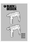
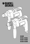
KR540
KR550
KR600
KR650F
06-02-2001, 10:23
Congratulations!
On the purchase of your
Black & Decker corded drill.
To ensure the best results from your corded
drill please read these safety and usage
instructions carefully.
If you have any questions or queries after
reading this user manual please do not
hesitate to call our Service and Information
Centre, whose number you will find towards
the back of this user manual, or one of our
Authorised Repair Agents. A list of these
Agents and further information is available on
the Internet at www.2helpU.com.
KR540-600 UK p01-12
2
06-02-2001, 10:23
Contents
Page 4
Safety instructions
Double insulation
Page 5
Electrical safety
Mains plug replacement
Extension cables
Unwanted tools and the environment
The Black & Decker guarantee
Page 6
After sales service for your Black & Decker product
The after sales service policy
Accessories
Technical data
Features
Fitting the drill bit
Page 7
Removing the chuck
Fitting the side handle
Setting the adjustable depth stop
Preparing your drill for operation
Page 8
Using your drill
Handy hints
Cooling down
Overload
EC declaration of conformity
Black & Decker phone numbers and addresses
Guarantee card
KR540-600 UK p01-12
3
06-02-2001, 10:23
Corded drills user manual
SAFETY INSTRUCTIONS
Warning! When using electric tools, the following
basic safety precautions should always be taken to
reduce the risk of fire, electric shock and personal
injury. Read all these instructions before attempting to
operate the product and save this booklet.
For safe operation:
• Keep the work area clean. Cluttered areas and
benches invite injuries.
• Consider the work area environment. Do not expose
the power tool to rain and do not use in damp or wet
locations. Keep the work area well lit. Do not use
the power tool where there is a risk to cause fire
or explosion.
• Guard against electric shock. Avoid body contact,
where possible, with earthed or grounded surfaces
(e.g. pipes, radiators, ranges and refrigerators).
• Keep children away. Do not let visitors touch the
tool or extension cord. All visitors should be kept
away from the work area.
• Store idle tools. When not in use, tools should be
stored in a dry, high or locked place, out of reach
of children.
• Do not force the tool. It will do the job better and
more safely at the rate for which it was intended.
• Use the right tool. Do not force small tools or
attachments to do the job of a heavy duty tool.
Do not use the tool for purposes not intended; for
example, do not use a circular saw to cut tree
limbs or logs.
• Dress properly. Do not wear loose clothing or
jewellery as they can be caught in moving parts.
Rubber gloves and non-skid footwear are
recommended when working outdoors. Wear
protective hair covering to contain long hair.
• Use safety glasses. Use a face or dust mask as well,
if the operation is dusty or if the tool is being used in
enclosed spaces.
• Connecting dust extraction equipment. If devices
are provided for the connection of dust extraction
and collection ensure these are connected and
properly used, especially in confined areas.
• Do not abuse the cord. Never carry the tool by its
cord or yank it to disconnect it from the socket. Keep
the cord away from heat, oil and sharp edges.
• Secure the work. Use clamps or a vice to hold the
work. It is safer than using a hand and it frees both
hands to operate the tool.
• Do not overreach. Keep proper footing and balance at
all times.
• Maintain the tool with care. Keep a cutting tool
sharp and clean for better and safer performance.
Follow the instructions for lubricating and changing
accessories. Inspect the tools cord periodically and,
if damaged, have repaired by an authorised service
facility. Inspect the extension cord periodically and
replace if damaged. Keep the handles dry, clean and
free from oil and grease.
• Disconnect the tool when not in use, before
servicing and when changing accessories such as
blades, bits and cutters.
• Remove adjusting keys and wrenches. Form the
habit of checking to see that keys and adjusting
wrenches are removed from the tool and replaced in
the storage area before switching on.
• Avoid unintentional starting. Do not carry a
plugged-in tool with a finger on the switch.
Ensure the switch is off when plugging in.
• Use an outdoor extension cord. When a tool is used
outdoors, only use an extension cord intended for
outdoor use and so marked.
• Stay alert. Watch what you are doing, use common
sense and do not operate the tool when tired.
• Check damaged parts. Before further use of the tool,
a guard or other part that is damaged should be
carefully checked to determine whether it will
operate properly and perform its intended function.
Check for alignment of moving parts, free running of
moving parts, breakage of parts, mounting and any
other conditions that may affect its operation. A
guard or other part that is damaged should be
properly repaired or replaced by an authorised
service centre unless otherwise indicated in the
product booklet. Have defective switches replaced
by an authorised service centre. Do not use the tool
if the switch does not turn it on and off.
• Warning! The use of any accessory or attachment,
other than recommended in the product booklet,
may present a risk of personal injury.
• Have the tool repaired by a qualified person. The
electrical tool is in accordance with the relevant
safety requirements. Repairs should only be carried
out by qualified persons using original spare parts,
otherwise, this may result in considerable danger to
the user.
Save these instructions!
DOUBLE INSULATION
The tool is double insulated. This means that all
the external metal parts are electrically insulated
4
KR540-600 UK p01-12
4
06-02-2001, 10:23
ENGLISH
from the mains power supply. This is done by
placing insulation barriers between the
electrical and mechanical components making
it unnecessary for the tool to be earthed.
Note: Double insulation does not take the place
of normal safety precautions when operating the
tool. The insulation system is for added protection
against injury resulting from a possible electrical
insulation failure within the tool.
ELECTRICAL SAFETY
Be sure the supply is the same as the voltage given on
the rating plate. The tool is fitted with a two-core cable
and plug.
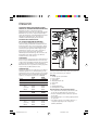
MAINS PLUG REPLACEMENT (UK ONLY)
Should the mains plug need replacing and you are
competent to do this, proceed as instructed below.
If you are in doubt, contact a Black & Decker service
centre or a qualified electrician.
• Disconnect the plug from the power supply.
• Cut off the plug and dispose of safely. A plug with
bared copper conductors is very dangerous if
engaged in a live socket outlet.
• Only fit BS1363A approved plugs fitted with the
correctly rated fuse.
Note: Fuses do not give personal protection against
electric shock.
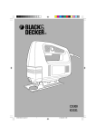
• The cable wire colours, or a letter, will be marked at
the connection point of most good quality plugs.
Attach the wires to their respective points in the plug
(see diagram). Brown is L (live) and blue is N (neutral).
Fit a BS1363A
approved
resilient plug
Fit a 5 amp fuse
approved
to BS1362
E
L
N
Connect
blue to
N (neutral)
Connect
brown to
L (live)
Make sure that the
outer sheath of the
cable is held firmly
by the clamp
230 volts AC only
Never use a light
socket
• Before replacing the top cover of the plug ensure
that the cable restraint is holding the outer sheath of
the cable firmly and that the two leads are correctly
fixed at the terminal screws. If the fuse cover is
missing or damaged do not use the plug.
For replacement or detachable fuse covers,
contact a Black & Decker service centre.
Warning! Never connect live or neutral wires to the
earth pin marked E or
.
MAINS PLUG REPLACEMENT
(AUSTRALIA AND NEW ZEALAND ONLY)
Should the mains plug or cordset of the product be
damaged, it must only be replaced by an authorised
Black & Decker service agent because special
purpose tools are required.
EXTENSION CABLES
Up to 30m (100ft) of 3-core extension cable can be used
without undue loss of power.
Note: An extension cable should not be used unless
absolutely necessary. Use of an improper extension
cable could result in a risk of fire and electric shock.
If an extension cable must be used, make sure it is
properly wired, contains the correct rated fuse as
recommended in its literature and is in good
electrical condition.
UNWANTED TOOLS AND THE ENVIRONMENT
Should you find one day that the tool needs
replacement or is of no further use, think of the
protection of the environment. Black & Decker
service agents will accept old tools and will
dispose of them in an environmentally safe way.
THE BLACK & DECKER GUARANTEE
(UK, AUSTRALIA AND NEW ZEALAND ONLY)
If the Black & Decker product becomes defective due
to faulty materials and workmanship, within 24 months
from the date of purchase, we guarantee to either
replace all defective parts or at our discretion, replace
the unit free of charge provided that:
• The product is returned to us or our authorised
repairers with evidence of date of purchase.
• The product has not been used for trade,
professional or hire purposes.
• The product has not been subjected to misuse
or neglect.
• The product has not sustained any damage through
foreign objects, substances or accidents.
• Repairs have not been attempted by anyone other
than our authorised repair distributors.
This guarantee is offered as an extra benefit and is
additional to the customers statutory rights.
5
KR540-600 UK p01-12
5
06-02-2001, 10:23
ENGLISH
AFTER SALES SERVICE FOR THE BLACK & DECKER
PRODUCT (UK, AUSTRALIA AND NEW ZEALAND ONLY)
Black & Decker offers a nationwide network of
authorised service agents. The use of other than genuine
Black & Decker accessories and parts may damage or
reduce the performance of your Black & Decker product
and may also endanger the user. The terms and
conditions of the warranty may also be effected.
OUR AFTER SALES SERVICE POLICY
(UK, AUSTRALIA AND NEW ZEALAND ONLY)
It is our aim that all Black & Decker customers
should be totally satisfied with their Black & Decker
product and after sales service, but if help or advice
is needed please contact your local Black & Decker
authorised repair agent who will be happy to help.
Full details of our after sales service and a list of
these agents can be found on the Internet at
www.2helpU.com. Alternatively, call our Service and
Information Centre whose number you will find
towards the back of this manual.
ACCESSORIES
The performance of any power tool is dependant upon
the accessory used. Black & Decker accessories are
engineered to high quality standards and are designed
to enhance the performance of your tool. Buying a
Black & Decker accessory will ensure that you get the
very best from your Black & Decker tool.
TECHNICAL DATA
The level of sound pressure of the tool is in accordance
with EEC legislation. It is recommended that you take
appropriate measures for the protection of your hearing
if the sound level seems uncomfortable. This normally
equates to a sound pressure in excess of 85dB (A).
KR540
KR550
Voltage
230V
230/240V
Power
540W
550W
No load speed
0-2800min-1
0-2800min-1
Drilling capacities:
Steel
Concrete
Wood
13mm
13mm
25mm
13mm
13mm
25mm
Voltage
KR600
230/240V
KR650F
230/240V
Power
600W
650W
No load speed
0-3000min-1
0-3000min-1
Drilling capacities:
Steel
Concrete
Wood
13mm
13mm
25mm
13mm
13 mm
25 mm
y
@
À
,
@ y,À@
À
,
y
@
À
,
y
@@,@Ày
ÀÀ
,,
yy
@@
ÀÀ
,,
yy
8
7
5
6
3
•
•
6
2
•
•
•
1
•
8
7
5
6
3
•
•
4
•
•
•
•
2
1
•
Note: This user manual also covers more than one
catalogue number within this product group. Refer to
your carton for details of your product.
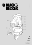
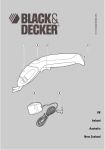
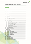
FEATURES
1. Variable speed on/off switch
2. Lock-on button
3. Side handle
4. Adjustable depth stop
5. Chuck jaws
6. Chuck
7. Hammer/drill switch
8. Forward/reverse switch
Your drill includes some or all of these features.
• The on/off switch or variable speed switch is used
to operate your drill in all modes of operation.
• The lock-on button provides continuous operation
of your drill.
• The side handle gives a secondary gripping position
for your drill.
• Your drill can operate as a hammer drill or as a
rotary drill depending on the setting of the
hammer/drill switch.
6
KR540-600 UK p01-12
4
•
06-02-2001, 14:05
ENGLISH
• The forward/reverse switch controls the direction
of rotation when your drill is used as a
screwdriver, or when clearing a jammed drill bit.
• The adjustable depth stop gives precise control of
the hole depth, when you drill blind holes.
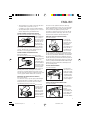
FITTING THE DRILL BIT (KEYLESS CHUCKS)
Disconnect the plug from the electricity supply.
While holding the
rear section of
the chuck, rotate
the front section
until the jaws of
the chuck are
sufficiently open.
Insert the drill bit in the jaws of the chuck. Hold the
rear section of the chuck while tightening the front
section. Twist the two sections firmly in opposite
directions to securely grip the drill bit.
FITTING THE DRILL BIT (KEYED CHUCKS)
Proceed as follows:
Disconnect the plug from the electricity supply.
Rotate the barrel
of the chuck until
the jaws are
sufficiently open.
Insert the drill bit
in the jaws of the
chuck. Insert the
chuck key with
the end of the chuck key in one of the three holes in
the body of the chuck, ensuring the head of the
chuck key is engaged with the barrel of the chuck.
Turn the chuck key clockwise to tighten the jaws and
securely grip the drill bit. Remove the chuck key.
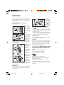
REMOVING THE CHUCK (KEYLESS CHUCKS)
Proceed as follows:
To remove the chuck, open the jaws, hold it firmly in
one hand and with a screwdriver held in the other
hand, turn the set-screw in the chuck clockwise
approximately one turn, to loosen it.
Place an allen
key in the chuck
and tighten the
jaws. Give the
allen key a short
powerful blow in
an anti-clockwise
direction with a
hammer to loosen
KR540-600 UK p01-12
7
the chuck on the spindle. Remove the allen key.
Use the screwdriver to turn the set-screw clockwise
until it totally disengages from the spindle. Remove
the chuck from the spindle by rotating it anticlockwise. To fasten the chuck, put it on the thread
and turn it clockwise until it stops. Put in the screw
and turn it anti-clockwise until absolutely firm.
REMOVING THE CHUCK (KEYED CHUCKS)
Proceed as follows:
To remove the
chuck, open the
jaws of the chuck
with the chuck
key. Hold the
chuck firmly in one
hand, and with a
screwdriver turn
the screw set in
the chuck clockwise with the other hand until it comes
out. Use only the correct chuck key. Place the chuck key
into the chuck, and hold the drill firmly in one hand with
the chuck pointing away from you. Rotate the chuck so
that the chuck key is just above the horizontal position on
the right hand side of the machine. Give the crossbar end
of the key a sharp downward blow with a mallet or light
hammer. The chuck should now be sufficiently loose to
be unscrewed by hand.
FITTING THE SIDE HANDLE
Proceed as follows:
,À@yy,À@
Loosely locate
the handle on the
body of your drill.
Rotate the handle
around the body
of your drill until
it is in the desired
position. Tighten
the handle by turning clockwise.
SETTING THE ADJUSTABLE DEPTH STOP
Proceed as follows:
Fit the drill bit.
Loosen the side
handle.
Slide the depth
stop until the end
of the depth stop
aligns with the
end of the drill bit.
,@Ày
yy
@@
ÀÀ
,,
@@
ÀÀ
,,
yy
06-02-2001, 10:23
7
ENGLISH
Slide the depth stop until the distance between the
end of the depth stop and the end of the drill bit is
equal to the length of the screw you will fit. Tighten
the side handle.
|
A
@
C
Á
À
Ã,
z
y
,
B
Â
{
C{
Ã
|
B
Â
PREPARING YOUR DRILL FOR OPERATION
Proceed as follows:
Fit the correct accessory for the job.
As a general
rule, for large
size drill bits use
low speeds and
for smaller drill
bits use high
speeds.
Set the forward/
reverse switch
to the desired
direction of
rotation. Never
change the
setting of the hammer switch, the speed switch or
the forward/reverse when your drill is in operation.
yy
@@
ÀÀ
,,
@@
ÀÀ
,,
yy
@@
ÀÀ
,,
yy
@@
ÀÀ
,,
yy
USING YOUR DRILL
To switch your
drill on, depress
the variable
speed on/off
switch.
Your drill stops
when the switch
is released.
If continuous
operation is
required,
depress the lockon button while
the variable
speed on/off
switch is
depressed.
To stop your drill
when operation is continuous, depress the switch
again and release. While your drill is in operation, do
not touch the chuck.
• Always hold your drill at right-angles to your work.
When drilling
wood and metal,
set the hammer
switch to the drill
mode
.
When drilling
masonry, set the
. When
hammer switch to the hammer mode
screwdriving, set the hammer switch to the drill
mode
.
• Set the forward/reverse switch to the correct direction.
• Never change the direction of rotation when your
drill is in operation.
• After use, remove the drill bit and gently tap the side
of the chuck with a soft-faced hammer to remove
the dust. This will extend the life of the chuck.
COOLING DOWN
If your drill becomes too hot in use, allow your drill to
operate without load for 2 minutes.
OVERLOAD
Never use excessive force when using your drill. Too
much pressure can reduce the speed of your drill and
reduce its efficiency. This can result in an overload
which can cause damage to the motor of your drill.
EC DECLARATION OF CONFORMITY
We declare that units: KR540RE, KR540CRE, KR550RE,
KR550CRE, KR600RE, KR600CRE, KR650CRF conform to
98/37/EC, 89/336/EEC, EN55014, 73/23/EEC, EN55104,
EN50144
A weighted sound pressure 99dB (A)
A weighted sound power 112dB (A)
Hand/arm weighted vibration 8.89m/s2
Brian Cooke - Director of Engineering
Black & Decker Ltd, Spennymoor, County Durham
DL16 6JG United Kingdom
The Black & Decker policy is one of continuous
improvement to our product and as such we reserve
the right to change the product specification without
prior notice.
HANDY HINTS
• Fit the correct size and type of drill or screwdriver bit.
• Always hold your drill using the handle and the
side handle.
8
KR540-600 UK p01-12
8
06-02-2001, 10:23
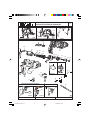
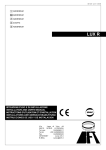
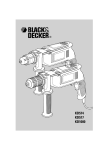
KR550RE KR600RE KR572 KR650CRF
KR540CRE KR550CRE KR600CRE
TYP.
1-2
104
104
104
123
122
125
123
120V
240V
KR550RE KR600RE KR540CRE KR550CRE KR600CRE KR650CRF
KR572
126
127
128
129
101
115
103
116
102
106 107
108 110
111
112 113
121
109
133
114
114
138
120
134
145
RE
CRE/CRF
146
133
103
139
132
140
135
KR550RE KR550CRE KR540CRE
KR600RE KR600CRE KR650CRF
105
KR572
141
128
128
105
129
129
105
119
129
119
119
TYPE 1
TYPE 2
E12545 / 374224-00
www.2helpu.com
18 - 08 - 2000
9
KR540-600 UK p01-12
9
06-02-2001, 10:23
Australia
DeWalt Power Tool Company Pty Ltd
7 Clarice Road, Box Hill
Victoria 3128
Tel: 03 9895 9200
Fax: 03 9899 7465
New Zealand
Black & Decker
483 Great South Road
Penrose, Auckland
Tel: 09 579 7600
Fax: 09 579 8200
South Africa
Black & Decker South Africa (Pty) Ltd
Suite no 107, PostNet X65
Halfway House 1685
Tel: 011 314 4431
Fax: 011 314 4435
United Kingdom
Black & Decker
210 Bath Road, Slough
Berkshire SL1 3YD
Tel: 01753 574277
Tlx: 848317 BAND MH
Fax: 01753 551155
Part no: 374225-02 2/01.2
KR540-600 UK p01-12
10
06-02-2001, 10:23
KR540-600 UK p01-12
11
06-02-2001, 10:23
Data protection act: Tick this box if you prefer not to receive
information from Black & Decker or other companies.
Product catalogue number: KR_ _ _ / _ _ _
Country:
Postcode:
County or state:
Town:
House number or name and street:
Name:
Address of the dealer where your drill was purchased:
Yes
Address of the dealer where your drill was purchased:
What was the price of your drill?
Was your drill bought as a replacement?
Was your drill your first purchase?
Was your drill a gift?
Date of your purchase:
No
GUARANTEE CARD FOR THE UK, IRELAND AND SOUTH AFRICA
South Africa: Black & Decker South Africa (Pty) Ltd, Suite no 107, PostNet X65, Halfway House 1685
United Kingdom & Ireland: PO Box 821, Slough, Berkshire, SL1 3AR
06-02-2001, 10:23
12
KR540-600 UK p01-12
Please complete this section immediately after the purchase of your corded drill
and post it to the Black & Decker address in your country (above).
If you live in Australia or New Zealand, please register your purchase by using the
alternative guarantee card supplied.
Part no: 374225-02 2/01.2