1
Wireless Bear Tracking System
Final Document
Clients
Digi, International
Wildlife Research Institute
Faculty Advisor
Dr. Ahmed Kamal
Team Members
Zach Bruce
Blane Chesnut
Chris Donnelly
John Pritchard
Adam Rasmussen
Forward
This document includes information about every aspect of the 2010 Senior Design Project for
group 10, Wireless Bear Tracking. This document was pieced together over a two semester
period and includes information about the design and then the implementation. This project
will need to be completed in another phase of the project, so this document will be important
to understand the progress of the project.
The main sections of the document are: Introduction, Design Requirements, Approach and
Product Design, Implementation, Test Cases, Schedule, and Resources. The approach section
details all of the possibilities for the design that were researched including the actual design
that was selected. The implementation section discusses the completed prototype and what
parts were finalized as well as any PIC code explanation. The test case section details the
different testing procedures that were used to verify the system as well as the results from
those testing procedures.
The table of contents follows as an outline to the document.
Wireless Bear Tracking, Group May1010
Page 2
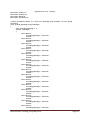
Table of Contents
1.
2.
3.
Introduction ......................................................................................................................... 13
1.1.
Executive Summary ..................................................................................................... 13
1.2.
Acknowledgments......................................................................................................... 14
1.3.
Problem Statement ....................................................................................................... 15
1.4.
Operating Environment ............................................................................................... 15
1.5.
Intended Use and Intended Users ............................................................................... 15
1.6.
Assumptions .................................................................................................................. 15
1.7.
Limitations .................................................................................................................... 16
1.8.
Expected End Product and Other Deliverables ........................................................ 16
Design Requirements ........................................................................................................... 17
2.1.
Functional Requirements ............................................................................................ 17
2.2.
Non-Functional Requirements .................................................................................... 18
2.3.
Technology Requirements ........................................................................................... 18
Approach and Product Design Results .............................................................................. 19
3.1.
Overall Bear Tracking Structure................................................................................ 19
3.1.1.
VHF Collar Units with VHF Routing Unit ............................................................. 19
3.1.2.
VHF Collar Units with OrbCom Routing Unit ....................................................... 19
3.1.3.
VHF Collar Units with Digi 9Xtend Routing Unit ................................................. 20
3.1.4.
Other Inappropriate Solutions ................................................................................. 20
3.1.5.
Detailed Design ....................................................................................................... 21
3.2.
Network Structure........................................................................................................ 22
3.2.1.
CSMA/CA............................................................................................................... 22
3.2.2.
TDMA ..................................................................................................................... 22
3.2.3.
Detailed Design ....................................................................................................... 22
3.3.
VHF Transceiver .......................................................................................................... 29
3.3.1.
Frequency Selection ................................................................................................ 29
3.3.2.
Transceiver Selection .............................................................................................. 30
3.3.3.
Detailed Design ....................................................................................................... 31
3.4.
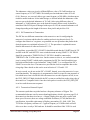
VHF Antenna ................................................................................................................ 42
3.4.1.
¼ Wavelength Whip Antenna ................................................................................. 43
Wireless Bear Tracking, Group May1010
Page 3
3.4.2.
½ Wavelength Whip Antenna ................................................................................. 45
3.4.3.
Sleeve Dipole Antenna ........................................................................................... 45
3.4.4.
Normal Mode Helical Antenna ............................................................................... 46
3.4.5.
Rotating Directional Antenna ................................................................................. 47
3.4.6.
Helical Antenna Array ............................................................................................ 48
3.4.7.
Yagi Antenna Array ................................................................................................ 49
3.4.8.
Detailed Design ....................................................................................................... 50
3.5.
GPS Module .................................................................................................................. 52
3.6.
GPS Antenna ................................................................................................................ 52
3.6.1.
GPS Helix Antenna ................................................................................................. 53
3.6.2.
Passive GPS Patch Antenna .................................................................................... 53
3.6.3.
Active GPS Patch Antenna ..................................................................................... 54
3.6.4.
Detailed Design ....................................................................................................... 54
3.7.
Microcontroller............................................................................................................. 54
3.8.
Chassis ........................................................................................................................... 55
3.8.1.
Commercial Cases .................................................................................................. 55
3.8.2.
Industrial Cases ....................................................................................................... 56
3.8.3.
Detailed Design ....................................................................................................... 56
3.9.
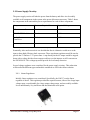
Power Supply Circuitry ............................................................................................... 57
3.9.1.
Linear Regulators .................................................................................................... 57
3.9.2.
Switching Regulators .............................................................................................. 58
3.9.3.
Detailed Design ....................................................................................................... 59
3.10. Battery ........................................................................................................................... 63
4.
3.10.1.
Nickel Metal Hydride (NiMH) ............................................................................ 63
3.10.2.
Lithium Ion (Li-ion) ............................................................................................ 64
3.10.3.
Detailed Design ................................................................................................... 64
Implementation .................................................................................................................... 65
4.1.
Hardware ...................................................................................................................... 65
4.1.1.
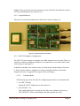
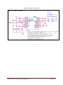
Printed Circuit Board Layout .................................................................................. 65
4.1.2.
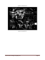
Populated Board ...................................................................................................... 67
4.1.3.
ADF-7021 Register Configuration ......................................................................... 67
Wireless Bear Tracking, Group May1010
Page 4
4.1.4.
4.2.
6.
7.
Hardware Modifications .............................................................................................. 82
4.2.1.
External Inductor L10 ............................................................................................. 82
4.2.2.
PIC Connection to Transceiver ............................................................................... 83
4.2.3.
Transceiver External Crystal................................................................................... 83
4.2.4.
I2C........................................................................................................................... 84
4.2.5.
Power ...................................................................................................................... 84
4.2.6.
Antenna ................................................................................................................... 84
4.3.
5.
Matching Networks ................................................................................................. 80
Software......................................................................................................................... 85
4.3.1.
PC Code .................................................................................................................. 85
4.3.2.
PIC Code ................................................................................................................. 86
System and Unit Level Test Cases.................................................................................... 101
5.1.
VHF Transceiver Unit Level Test Cases .................................................................. 101
5.2.
VHF Antenna Unit Level Test Cases ........................................................................ 101
5.3.
GPS Module Unit Level Test Cases .......................................................................... 102
5.4.
Microcontroller Unit Level Test Cases..................................................................... 102
5.5.
Chassis Unit Level Test Cases ................................................................................... 103
5.6.
Battery Unit Level Test Cases ................................................................................... 103
5.7.
Power Supply Circuit Unit Level Test Cases ........................................................... 103
5.8.
System Test Cases....................................................................................................... 104
System and Unit Level Test Case Results ........................................................................ 106
6.1.
VHF Spectrum ............................................................................................................ 106
6.2.
Antenna ....................................................................................................................... 111
6.3.
Google Maps ............................................................................................................... 113
6.4.
Specific Absorption Rate Safety................................................................................ 113
Recommendation for Project Continuation .................................................................... 114
7.1.
VHF Recommendations ............................................................................................. 114
7.2.
Power Section Recommendations ............................................................................. 114
7.3.
USB Section Recommendations ................................................................................ 114
7.4.
GPS Section Recommendations ................................................................................ 115
7.5.
General Design Recommendations ........................................................................... 115
Wireless Bear Tracking, Group May1010
Page 5
8.
9.
Statement of Work............................................................................................................. 116
8.1.
Task 1 - Problem Definition ...................................................................................... 117
8.2.
Task 2 - Technology Research and Selection ........................................................... 117
8.3.
Task 3 - End-Product Design .................................................................................... 119
8.4.
Task 4 - End-Product Prototype Development........................................................ 119
8.5.
Task 5 - End-Product Testing ................................................................................... 120
8.6.
Task 6 – Presentations ............................................................................................... 121
8.7.
Task 7 - Product Documentation .............................................................................. 121
Resources and Schedule .................................................................................................... 123
9.1.
Resources..................................................................................................................... 123
9.2.
Schedule....................................................................................................................... 124
10. Closure Material ................................................................................................................ 126
10.1. Project Contact Information ..................................................................................... 126
10.2. Closing Summary ....................................................................................................... 127
Wireless Bear Tracking, Group May1010
Page 6
List of Tables
Table 1: VHF to PIC I/O Descriptions ......................................................................................... 33
Table 2: Timing Table for ADF7021 (Analog Devices, 2009) .................................................... 34
Table 3: RF Switch Control Lines ................................................................................................ 42
Table 4: Nema Case Standards (Computer Dynamics) ................................................................ 56
Table 5: Power Requirements ....................................................................................................... 57
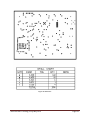
Table 6: PCB Characteristics ........................................................................................................ 66
Table 7: TX Register 1 value ........................................................................................................ 68
Table 8: TX Register 3 value ........................................................................................................ 68
Table 9: TX Register 0 value ........................................................................................................ 70
Table 10: VHF Muxout Settings ................................................................................................... 71
Table 11: TX Register 2 value ...................................................................................................... 71
Table 12: PA output power ........................................................................................................... 72
Table 13: TX Bit Latency ............................................................................................................. 73
Table 14: TX Register 0 power down value ................................................................................. 73
Table 15: RX Register 1 value ...................................................................................................... 74
Table 16: RX Register 3 value ...................................................................................................... 74
Table 17: RX Register 6 value ...................................................................................................... 74
Table 18: RX Register 5 value ...................................................................................................... 75
Table 19: RX Register 11 value .................................................................................................... 76
Table 20: RX Register 12 value .................................................................................................... 77
Table 21: RX Register 0 value ...................................................................................................... 77
Table 22: RX Register 4 value ...................................................................................................... 77
Table 23: RX Register 10 value .................................................................................................... 79
Table 24: Gain Mode Correction (Analog Devices) ..................................................................... 92
Table 25: 4B/5B Encoding............................................................................................................ 99
Table 26: Packet Format Size Before Encoding ......................................................................... 100
Table 27: Tasks to be accomplished ........................................................................................... 116
Table 28: Single Unit Estimated Cost ......................................................................................... 123
Table 29: Project Costs ............................................................................................................... 123
Wireless Bear Tracking, Group May1010
Page 7
List of Figures
Figure 1: VHF/UHF Solution ....................................................................................................... 17
Figure 2. Network Example .......................................................................................................... 23
Figure 3. TDM General Diagram.................................................................................................. 24
Figure 4. Time Slot Assignment ................................................................................................... 28
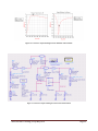
Figure 5. System Block Diagram .................................................................................................. 32
Figure 6. Interface of Transceiver and RF Switch to Microcontroller ......................................... 33
Figure 7. Timing Diagram for Writing to ADF7021 Registers (Analog Devices) ....................... 34
Figure 8. Timing Diagram for Readback (Analog Devices) ......................................................... 35
Figure 9. Transmit sequence after power up (Analog Devices, 2009) ......................................... 36
Figure 10. Receive sequence after power up (Analog Devices, 2009) ......................................... 37
Figure 11. RF Output Matching Network ..................................................................................... 39
Figure 12. RF Output Matching Network Simulation .................................................................. 39
Figure 13. RF Input Matching Network ....................................................................................... 40
Figure 14. RF Input Matching Network Simulation ..................................................................... 40
Figure 15. ADF7021 Simulations ................................................................................................. 41
Figure 16. Example Whip Collar Antenna(Advanced Telemetry Systems) ................................. 44
Figure 17. Sleeve Dipole Antenna(Saunders and Aragon-Zavala) ............................................... 46
Figure 18. Helical Antenna (Burberry) ......................................................................................... 48
Figure 19. Six Element Yagi Antenna(Setian) ............................................................................. 49
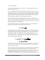
Figure 20. Radio Mobile Area of Concern ................................................................................... 51
Figure 21. Radio Mobile Router Station Propagation .................................................................. 52
Figure 22. LM317 ......................................................................................................................... 57
Figure 23. LM2717 ....................................................................................................................... 58
Figure 24. MAX863 ...................................................................................................................... 58
Figure 25. ADP3050 ..................................................................................................................... 59
Figure 26. ADP3050 General Circuit ........................................................................................... 59
Figure 27. 3.3V ESR Calculations ................................................................................................ 60
Figure 28. 5V ESR Calculations ................................................................................................... 62
Figure 29: PCB Layout Structure ................................................................................................. 65
Figure 30: Populated Printed Circuit Board.................................................................................. 67
Figure 31: Transceiver output matching network simulation circuit with non-ideals .................. 80
Figure 32: Transceiver output matching network simulation with non-ideals ............................. 81
Figure 33: Transceiver input matching network circuit with non-ideals ...................................... 81
Figure 34: Transceiver input matching network simulation with non-ideals ............................... 82
Figure 35: RF output vs. total external inductance (Analog Devices, 2009) ................................ 82
Figure 36. Quarter-Wave Antenna Construction .......................................................................... 85
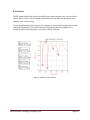
Figure 37: Output Spectrum of board A with transceiver set at level 1 power (-16 dBm) ......... 107
Figure 38: Output Spectrum of board A with transceiver set at level 36 power (~0 dBm) with
span 50 kHz................................................................................................................................. 107
Wireless Bear Tracking, Group May1010
Page 8
Figure 39: Output Spectrum of board A with transceiver set at level 36 power (~0 dBm) with
Span 2.6 MHz ............................................................................................................................. 108
Figure 40: Output Spectrum of board A with transceiver set at level 63 power (13 dBm) ........ 108
Figure 41: Spectrum of board B with modification and transceiver output power level of 1 (-16
dBm) ........................................................................................................................................... 109
Figure 42: Spectrum of board B with modification and transceiver output power level of 36 (~0
dBm) ........................................................................................................................................... 109
Figure 43: Spectrum of board B with modification and transceiver output power level of 63 (13
dBm) ........................................................................................................................................... 110
Figure 44. Antenna A - S11 Parameters ..................................................................................... 111
Figure 45. Antenna 2 - S11 Parameters ...................................................................................... 112
Figure 46 Port parameters for communication to PC for Google Map testing ........................... 113
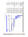
Figure 47: Schedule for Project .................................................................................................. 125
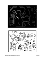
Figure 48: Top Copper Layer ..................................................................................................... 139
Figure 49: Bottom Copper Layer ................................................................................................ 140
Figure 50: Top Solder Mask ....................................................................................................... 140
Figure 51: Bottom Solder Mask .................................................................................................. 141
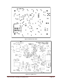
Figure 52: Top Silk Screen ......................................................................................................... 141
Figure 53: Bottom Silk Screen .................................................................................................... 142
Figure 54: Drill Chart.................................................................................................................. 143
Wireless Bear Tracking, Group May1010
Page 9
Appendices
Appendix 1: Operations Manual Done by Joe Lane ................................................................... 129
Appendix 2: Operations Manual Done by Jamin Hitchcock ...................................................... 132
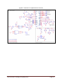
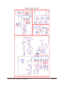
Appendix 3: VHF and Power Amplifier Revision A Schematic ................................................ 135
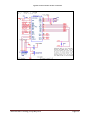
Appendix 2: Microcontroller Revision A Schematic.................................................................. 136
Appendix 5: GPS Revision A Schematic.................................................................................... 137
Appendix 6: Power Supply ......................................................................................................... 138
Appendix 7: PCB Layout Layers ................................................................................................ 139
Appendix 8: Revision B Schematic ............................................................................................ 144
Appendix 9: PC Code ................................................................................................................. 145
Appendix 10: PIC Code – main.c ............................................................................................... 146
Appendix 11: PIC Code – main.h ............................................................................................... 152
Appendix 12: PIC Code – init.c .................................................................................................. 153
Appendix 13: PIC Code – init.h.................................................................................................. 161
Appendix 14: PIC Code – datatypes.h ........................................................................................ 162
Appendix 15: PIC Code – handler.h ........................................................................................... 163
Appendix 16: PIC Code – handler.h ........................................................................................... 178
Appendix 17: PIC Code – interrupts.c ........................................................................................ 179
Appendix 18: PIC Code – interrupts.h ........................................................................................ 183
Appendix 19: PIC Code – projconfig.h ...................................................................................... 184
Appendix 20: PIC Code – encoding.c......................................................................................... 185
Appendix 21: PIC Code – encoding.h ........................................................................................ 193
Appendix 22: PIC Code – eeprom_i2c.c .................................................................................... 194
Appendix 23: PIC Code – eeprom_i2c.h .................................................................................... 199
Appendix 24: PIC Code – gps_i2c.c ........................................................................................... 201
Appendix 25: PIC Code – gps_i2c.h........................................................................................... 207
Appendix 26: PIC Code – ublox_cfg.c ....................................................................................... 209
Appendix 27: PIC Code – ublox_cfg.h ....................................................................................... 212
Appendix 28: PIC Code – ublox_read.c ..................................................................................... 214
Appendix 29: PIC Code – ublox_read.h ..................................................................................... 218
Wireless Bear Tracking, Group May1010
Page 10
Definitions
ACK
Acknowledgement
ADC
Analog to digital conversion
AFC
Automatic frequency control
ASK
Amplitude-shift Keying
BER
Bit Error Rate
bps
Bits per second
CRC
Cyclical Redundancy Check
CSMA/CA Carrier sense multiple access with collision avoidance
dBm
Decibel referenced to milliwatts
ESR
Effective Series Resistance
FCC
Federal Communications Commission
FM
Frequency Modulation
FSK
Frequency-shift Keying
GPS
Global Positioning System
I/O
Input and Output
IF
Intermediate Frequency
ISM
Industrial, Scientific, and Medical Equipment
LEO
Low Earth Orbiting, used in describing satellite orbits
MAC
Media Access Control
MSK
Minimum-shift keying
PA
Power Amplifier
PC
Personal Computer
PIC
Programmable Integrated Circuit
Wireless Bear Tracking, Group May1010
Page 11
POR
Power on Reset
RF
Radio Frequency
RSSI
Received signal strength indication
RX
Receive
SAR
Specific Absorption Rate
SPOT
Commercially available personal tracking unit, which uses satellites for
communication
Sync
Synchronize
TDM
Time Division Multiplexing
TDMA
Time Division Multiple Access
Term
Description
TX
Transmit
UART
Universal asynchronous receiver/transmitter
UHF
Ultra High Frequency, the radio frequency range from 300 MHz to 3 GHz
URL
Uniform Resource Locator
VHF
Very High Frequency, the radio frequency range from 30 MHz to 300 MHz
Wireless Bear Tracking, Group May1010
Page 12
1. Introduction
The following is an overview of the Wireless Bear Tracking Senior Design Project. This
section includes background on the device, the problem statement, possible solutions, and the
product deliverables.
1.1.Executive Summary
A non-profit group from northern Minnesota researches a group of twelve mother bears by
tracking their movements using RF transmitting collars worn by the bears. These bears are
habituated to the researchers and allow them to approach and remove collars as well as take
different measurements and notes. The researchers track the mother bears because they are
more territorial and will stay within a twenty-five mile by ten mile area. The tree cover in this
area is extremely dense. It is important to gather live data of the location of the bears,
especially when the bears go into caves during winter to hibernate as well as when they leave
the caves in the spring.
The previous solution to this tracking did not even provide live data. The bears had worn
collars that transmit on a VHF band. Each collar outputs at a specified frequency, and the
researchers were required to travel and locate the bears individually by monitoring the
strength of signals transmitted. These collars were very reliable and transmitted well through
the trees. The battery life was also superb and lasted nearly five years. The collars would wear
through before the batteries were depleted.
This summer, these VHF collars are being phased out by GPS personal tracking devices called
SPOT. These devices were modified to continually ping their data and send live location
information up to a low earth orbiting satellite and then to the cabin. This system fits well on
the collar, but in a dense forest, the signal is often lost for up to two hours. The SPOT units
also require a monthly fee. It is also very difficult to get decent battery life, for the collars
have batteries that must be changed every week. Still, the researchers prefer the live location
data to the old VHF system.
Digi, International has taken the task of providing a new collar for the researchers as a nonprofit project. They are supporting the project financially and through their technical expertise
and advice.
The goal of this project is to create a new collar that will continually and reliably send
location data to the researchers. This unit must run on battery for at least 6 months, and
transmit location about every fifteen minutes. It is also important to make the unit durable and
smaller than the current SPOT units.
Wireless Bear Tracking, Group May1010
Page 13
The collar will consist of the basic building blocks of GPS, VHF transceiver, PIC
microcontroller, and power electronics, as shown in Figure 5.
The collars will transmit their GPS location via VHF frequencies to various router units. All
units will transmit on the same frequency, 217 MHz, and the system will use a time division
multiplexing network scheme. The router and collar units will have similar hardware, with
minor differences in the VHF antenna and battery. A home base router will output the data
serially to be easily plotted as data points on Google maps or similar mapping software.
The current units are very expensive, nearing $2000. The units we are developing will be
much less expensive. Estimated unit cost is around $290. Digi, International is providing all of
the materials and financing necessary to complete the project.
Prototypes will be available by April so the bears can be collared after they have left
hibernation. There will be three collar units and two router units available to test. The
mechanical design and the computer mapping interface are not the focus of this stage in the
project. In the future these may be developed by another senior design team, or engineers at
Digi.
1.2.Acknowledgments
Digi, International is going to supply all of the necessary parts and funding for the project.
This is a non-profit task that they have decided to support and are going to help with any
aspect of the product. They will provide technical assistance as needed. Technical expertise
has been provided by James Puzzo, Jordan Husney, Mark Tekippe, and Jim Stroner.
Technical expertise has been provided by ISU Faculty including Dr. Ahmed Kamal, Dr.
Nathan Neihart, Dr. Jiming Song, Dr. Mani Mina, Leland Harker, and Matthew Nelson.
Wireless Bear Tracking, Group May1010
Page 14
1.3.Problem Statement
Black bears need to be tracked live from a remote location. The area of concern will be
approximately a 25 mile by 10 mile plot. It is difficult to transmit a signal in this area due to
dense foliage. A collar unit must be developed that can transmit tracking data every ten to
fifteen minutes. This unit must be smaller than the current unit and ideally have a battery life
of six months. It is also important that the collar be individually identified and easily removed.
1.4.Operating Environment
The unit will be exposed to the harsh conditions of northern Minnesota. Temperatures range
from -30 to 70 ºC. The unit must be waterproof and weatherproof. The collar must be
comfortable on the bear, or the bear will tear the collar off. The bear cubs also get restless
during the hibernation months and will proceed to chew and destroy the collar.
The collar unit must also be easily handled by the researchers. They must be able to simply
remove and ID each unit. The researchers are not as familiar with complicated technologies
and the unit must be as user friendly as possible.
1.5.Intended Use and Intended Users
The intended use for the product is to track black bear mothers in a 25 by 10 mile area. The
collar must function in this area, and if successful, it can be transferred to other wildlife
tracking areas as well. The collar will function properly in very dense forests.
The intended users are the bear researchers at the facility in Ely, Minnesota. These researchers
are Sue Mansfield and Lynn Rogers.
1.6.Assumptions
There are many assumptions taken into account when working on this project. It is difficult
for us to gain access to the forested area, so we must assume how certain signals will react to
the forest. We assume that the GPS signals will reach the collar if the collar is properly
located on the bear. We also assume that lower frequencies will penetrate the thick forest
better than the higher frequencies. We are using the SPOT unit as an acceptable size and
weight.
Digi will provide funding and technical advice, and it is assumed that this will continue
throughout the project.
Wireless Bear Tracking, Group May1010
Page 15
After the completion of this project, we do not expect to have much direct contact with the
researchers. We have to make the assumption that if the unit is well documented and
somewhat simple to use, the researchers will be able to properly use the unit without
supervision and guidance.
1.7.Limitations
Our basic limitations on this project are time and experience. We have only one year to
develop this prototype and a project such as this could easily be a several year project. All of
the group members are Electrical Engineers and our current knowledge base of networking
and programming is not as strong as required by this project. We will need to spend extra time
researching these technologies.
A second limitation has to do with access to the area. It is a nine hour drive to the forest and
we do not have the ability to test our equipment in a similar environment. We will have to
estimate and rely on different calculations to determine the best technology.
1.8.Expected End Product and Other Deliverables
At the end of the project the researchers expect three collar tracking units and two router units
to be prototyped and ready to field test.
Along with the prototypes, it is important to provide documentation on the device in terms of
a user manual and a technical specification document, so that it is easily modified and usable.
Suggestions for improving the unit as well as preliminary plans for the next generation are all
important deliverables.
Wireless Bear Tracking, Group May1010
Page 16
2. Design Requirements
The following describes the requirements defined for the project design. Any solution must
meet the requirements laid out in this section.
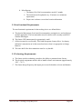
2.1.Functional Requirements
The VHF/UHF terrestrial communication solution will involve transmitters placed on the
bears to communicate with routers posted in selected spots within the area of concern. GPS
location information would be received by the modules on the collars and then transmitted to
the onsite routers. The routers would then relay the bears' GPS location information to an
onsite base station. This information would then be processed accordingly by the researchers.
See Figure 1.
GPS
Bear
VHF/UHF
Transmitter
VHF/UHF
Router A
VHF/UHF
Router B
Base Station
Figure 1: VHF/UHF Solution
The functional requirements pertaining to a VHF/UHF solution are defined below.
A. Local VHF/UHF Solution
a. Pertaining to the transmitter on the bear
i. The tracking device is required to receive GPS data via GPS satellites
ii. The tracking device is required to transmit data to routers, via local
VHF/UHF transmitters, stationed within defined area
b. Pertaining to the routing transceiver
i. The routing device is required to communicate with mobile units when
they are within their communication range.
ii. The routing device is required to communicate with other routing
devices
iii. Routing devices will cooperate to relay readings received from
tracking devices to the end user receiver
c. Pertaining to the end user receiver
i. The end device is required to receive data from multiple tracking
devices
ii. The end device is required to receive data from multiple routing
devices
iii. The end device is required to plot location information on a mapping
interface
Wireless Bear Tracking, Group May1010
Page 17
d. Miscellaneous
i. The battery life of the bear transmitter must be 3 months
ii. The location must be updated every 15 minutes as a minimum
requirement
iii. Proper care is taken to secure bear location information
2.2.Non-Functional Requirements
The non-functional requirements for the tracking device are defined below.
A. The physical dimensions of each unit (bear transmitter, routing device, and end device)
must be appropriate. The bear transmitter must be similar to the currently used SPOT
Satellite Messengers
B. The chosen VHF antenna must be appropriately small
C. All devices must be user friendly. This could incorporate features like a ‘low battery
indication’ transmission to let the researchers know when it is appropriate to change
batteries.
D. The outer shell of the bear transmitter must be very durable
2.3.Technology Requirements
A. The chosen wireless technology must have the ability to penetrate dense forestry
B. The electrical components must be able to handle extreme environments (approximately
-40˚C – 70˚C)
C. The chosen design frequency and output power must be harmless to bears and humans
Wireless Bear Tracking, Group May1010
Page 18
3. Approach and Product Design Results
The following describes the approach that will be taken to achieve the wireless bear tracking
solution. This section describes the overall system and network structure as well as the
individual components that will be included in the system. The considered approaches are all
evaluated, and the finalized approach is described in detail.
3.1.Overall Bear Tracking Structure
Having a functioning structure for communication is critical. We considered a number of
solutions including VHF, satellite, cellular, and Digimesh. From these choices, we narrowed
down our options based on pros and cons of each alternative.
3.1.1. VHF Collar Units with VHF Routing Unit
Collar unit will consist of a VHF transceiver that will allow data to transmit and receive
over VHF Frequencies to the nearest routing unit. The routing unit will use a
predetermined and programming network protocol to send information to collars and to
other routers until the information is received at the remote research station.
Pros
• Router and Collar will be very similar designs.
• The routers are able to be mounted in desirable locations to easily transmit.
• VHF can transmit at increased distances using lower power rates.
• VHF frequencies easily penetrate heavily wooded areas.
Cons
• Readily made VHF module is not easily accessible with high power output.
• The network protocol may be difficult to complete.
• Bears may travel outside the range of stationary routers.
3.1.2. VHF Collar Units with OrbCom Routing Unit
Collar unit will consist of a VHF Transceiver that will allow data to transmit and receive
over VHF Frequencies. The routing unit will transmit received data to the OrbCom
Satellites and the satellites will then transmit to a remote location.
Pros
• VHF can transmit at increased distances using lower power rates.
• VHF frequencies easily penetrate heavily wooded areas.
• OrbCom modules are manufactured by Digi.
Wireless Bear Tracking, Group May1010
Page 19
Cons
• Readily made VHF module is not easily accessible with high power output.
• OrbCom modules have high power requirements.
• Communication to satellite incurs a monthly fee.
• Modules are more expensive and not currently available from Digi.
• Bears may travel outside the range of stationary routers.
3.1.3. VHF Collar Units with Digi 9Xtend Routing Unit
Collar unit will consist of a VHF transceiver that will allow data to transmit and receive
over VHF Frequencies. The routing unit will consist of a Digi 9Xtend (900 MHz) unit
and be mounted above the tree line.
Pros
• VHF can transmit at increased distances using lower power rates.
• VHF frequencies easily penetrate heavily wooded areas.
• The 9Xtend module is manufactured by Digi.
• The 9Xtend module will make the network structure very easy to implement.
Cons
• Readily made VHF module is not easily accessible with high power output.
• Bears may travel outside range of stationary routers.
• The transmission of the 9Xtend was only tested to reach approximately 2.5 miles
with line of sight.
3.1.4. Other Inappropriate Solutions
The following solutions were looked into for a short period to evaluate their feasibility
but were quickly removed from consideration for the given reasons.
Cellular
• Tower coverage is extremely weak in area
• Subscription cost is expensive
• Difficult to certify device
• Signal is too high frequency
Wireless Bear Tracking, Group May1010
Page 20
IRIDIUM Satellite Communication
• No readily available module
• Too high frequency for good signal reception
Satellite Modem on Collar
• Both IRIDIUM and OrbCom constellations
• Too high of power for collared unit
• Modules too large for collared unit
DigiMesh 900MHz Collar Mounted Solution
• Signal power too low to give adequate transmission range.
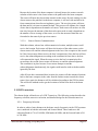
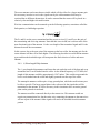
3.1.5. Detailed Design
The chosen solution was VHF Collar Units with VHF Routing Unit. After evaluating the
Orbcom solution, we realized that this was too similar to the solution currently being
used by the researchers and incurred the same sort of cost that they are looking to
eliminate. Next, we were able to rule out the Digi 9Xtend solution after doing field tests
that resulted in an unacceptable 2 mile range from line of sight. This transmission would
be drastically reduced in the wooded areas of Minnesota.
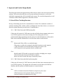
The VHF Routing Unit solution allowed for these constraints to be overcome. Not only is
it a low cost solution, but it also gives us the ability to choose a frequency that works best
for our conditions. With the selected frequency of 217 MHz, we are able to penetrate
very dense forestry while still maintaining a reasonable range. This was verified using the
Radio Mobile simulation software.
VH
F
R
ad
io
End User
Mapping
Server
VH
F
Ra
dio
R
VHF
adio
VHF Radio
Wireless Bear Tracking, Group May1010
Page 21
3.2.Network Structure
The following section will define the network routing schemes proposed and why TDMA
was chosen as the preferred networking method. The detailed design of the network method
is also described.
The sole purpose of this section is to propose a versatile solution to the unit to router
communication scheme as well as the router to router communication scheme.
3.2.1. CSMA/CA
CSMA/CA is a networking solution that stands for Carrier Sense Multiple Access with
Collision Avoidance. A user will listen to the channel for a period of time before
transmitting. If the channel is clear, the user will notify all other users not to transmit and
then proceed to transmit the information packet.
3.2.2. TDMA
TDMA will be described in depth in the detailed design section, but its basic concept is
that several users will transmit on the same frequency, but for different time slots. The
individual user is allocated a time to transmit and during that time period, the channel is
clear. After the time has passed, the channel is clear for a second user to transmit.
There were several reasons considered when choosing TDMA over CSMA/CA.
CSMA/CA is useful when users' activities are bursty, and also when the number of users
of the system varies dynamically. CSMA/CA allows simple adaptation to these
conditions. However, since in the current application the system is quasi-static and the
number of users does not change (except in rare situations), in addition to the fact those
users' activities are deterministic (1 report every 10 minutes), TDMA is better suited for
the application. Moreover, with TDMA, the hidden terminal problem can be avoided, the
exposed terminal problem can be avoided, and the ad hoc network topology can be
supported in a simple way. This strategy will also save energy since it will avoid the
collisions that CSMA/CA suffers from. The use of a GPS chip also makes
synchronization a simple task.
3.2.3. Detailed Design
This section gives an introduction to the overall network skeleton as well as the network
protocol chosen.
Wireless Bear Tracking, Group May1010
Page 22
3.2.3.1.
General Network Skeleton
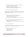
Consider the case where four routers are placed in predetermined spots within the
area of concern. Also consider several units scattered throughout this area but within
range of at least one router. This could be described in Figure 2 below.
Figure 2. Network Example
In the case above, there are nine users present in the network of four routers, the first
being home base. It is required that location data from each bear is routed to home
base every 10 to 15 minutes. All units and routers are transmitting and receiving the
same frequency, so a fitting modulation scheme needs to be decided upon.
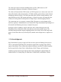
3.2.3.2.
General TDM
TDM (Time Division Multiplexing) is a great choice for this application. The idea is
that a data stream is divided into separate frames in the time domain. Multiple users
then share a piece of that frame (a time slot). Each user is allowed to transmit and
receive for the amount of time allotted in the time slot.
For example, consider Figure 3 below. The top section of this figure displays a data
stream of which is divided into separate frames. Each frame is then divided into
different time slots, in this case four. Thus, there are four possible users that can talk
to a host device at very specific times.
Wireless Bear Tracking, Group May1010
Page 23
Figure 3. TDM General Diagram
This model assumes that a connection has been previously established and time slots
have been assigned to each user. Connection establishment and time slot assignment
will be discussed later in this section.
Wireless Bear Tracking, Group May1010
Page 24
3.2.3.3.
General Network Structure
Consider again the example network shown in Figure 2, where nine users have data
routed to home base by three different routers. In this system, all routers are
constantly listening and do not turn off or sleep. The units only turn on when it is
their turn to speak. The unit will know when its turn to speak is based on the time slot
given. This timeslot, or specified amount of time where only one particular unit
speaks, is given to the unit prior to shipment and is hardcoded.
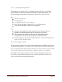
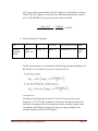
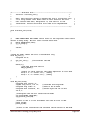
To determine the number of time slots available, the following equation can be used:
where TS is the number of time slots, baud is the bit rate (bits per second), bpTx is the
number of bits per transmission needed, td is the time needed for data transmission (in
seconds), and tg is the guard period (as shown in the previous diagram – two guard
periods are needed, one at the beginning and end of the frame, thus resulting in 2tg).
The lower the baud, the less number of time slots are available. Lower baud usually
results in lower BER and better penetration through the dense woods. The higher the
baud, the greater number of time slots available. Higher baud usually results in higher
BER and does not allow the signal to penetrate dense forestry as well. So, in selecting
the proper baud, tradeoffs need to be considered. The number of bits per transmission
should be static.
3.2.3.4.
Specific Unit Data Communication
The specific data needed by the router from the unit could be the following:
<preamble, data start string, UnitID, MAC, data, flags, CRC, data end
string>
The preamble will consist of 6 bytes of alternating ones and zeros. The purpose of the
preamble is to all the transceiver to synchronize with this incoming message. Data
start string is a unique set of characters that differentiates this message from any other
message. UnitID is the unit’s identifier which can be changed in software. MAC is
the unit’s unique MAC address; this is hardcoded and will never change. Data is the
information required to locate the bear. Flags are the bytes needed to let the router
know the status of the unit. CRC is the data needed for bit error checking and
Wireless Bear Tracking, Group May1010
Page 25
correcting. Data end string is the set of bits that lets the router know it has reached the
end of the message.
The unit will require an acknowledgment from the router letting the unit know that
the data was successfully received. This acknowledgment message sent by the router
is described as the following:
<preamble, ACK start string, MAC, time, CRC, ACK end string>
ACK start string is a unique set of characters that differentiates this message from any
other message. MAC is the address of the unit receiving the acknowledgement. The
time of the received GPS data is resent back to the collar unit for extra verification
that the ACK message corresponds to the recent message sent. CRC is the data
needed for bit error checking and correcting. ACK end string is the set of bits that lets
the router know it has reached the end of the message.
The transceiver can handle up to 8 bits of a constant one or zero. After this, the
performance starts to degrade. To address this issue, 8B/10B encoding scheme was
chosen. All packets will be encoding using this scheme.
It is predicted that at most 150 bytes will be needed for the unit to router data
message, and at most 25 bytes will be needed for the router to unit acknowledgment
message. So the total number of bytes needed for data transmission is 175 bytes. This
is a very high overestimate to prepare for a worst case scenario.
Referring to the previous equation, the number of time slots available can be
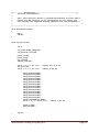
determined. The baud chosen initially is was 300. If 0.5 ms is allocated for the guard
periods, and 175 bytes are needed for data transmission only, then the time needed for
each time slot is:
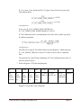
Nine bits per byte is used to account for the parity bit. If each frame is 10 minutes
long, the number of time slots available is:
Wireless Bear Tracking, Group May1010
Page 26
Here, it is shown that there are 114 time slots in a length of time equal to 10 minutes.
Each collar is given three time slots in order to achieve a successful transmission. If
the first attempt is successful, the collar will sleep for the additional two time slots it
is assigned. If each collar uses three time slots, this allows for 38 collars in this static
case of the system.
As location must arrive at the home base every fifteen minutes, the last five minutes
of the TDM allows for router to router communication. A later section defines how
the routers register with each other to transmit the information to the home base.
Routers will relay their unit information forward to the home base in a chain, until the
home base has received all of the data. The time slot for each router is assumed to be
the worst case scenario where it must send location information for all 38 collars.
After the routers have relayed the information to the home base, the 15 minute TDM
cycle will repeat.
3.2.3.5.
Time Slot Recognition
Assigning a time slot to a unit is a simple programming task, but introducing the unit
to the network with the assurance the unit properly utilizes the time slot is a more
difficult task. The unit can know precisely when to start and stop transmitting only if
it knows the current time of day. This can be known by using the GPS time.
3.2.3.6.
Initial Unit Perception of Time
Consider a unit that needs to begin transmitting on the :00, :10, :20, :30, :40, and :50
mark of every hour. This is hardcoded. By turning on the unit and allowing it to
receive a GPS signal, the time of day can be obtained, and a timer can be set to begin
waiting for the next time to reach its time slot. To be clear, say the time obtained is
12:15:25. The controller would then set a timer for 00:04:35 to begin transmitting.
3.2.3.7.
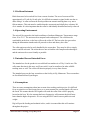
Specific Time Slot Assignment
To ensure minimal unit interruption, the time slot assignment for the collar units will
be staggered along the ten minute allotted time, allowing for ample wait time between
time slots.
Wireless Bear Tracking, Group May1010
Page 27
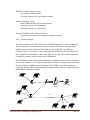
For example, consider a system that has eight allowed time slots for units to occupy.
Assume that only three units are registered to the system. Units 1, 2, and 3 would be
assigned time slots 1, 7, and 3 respectively. The diagram below illustrates this.
Figure 4. Time Slot Assignment
3.2.3.8.
Router Registration
The routers will be required to dynamically set up an appropriate network for
transferring the information from routers back to the home router. This section
describes that registration and initial set-up.
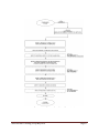
The router registration will execute the following:
Router will find the nearest adjacent router in the direction of the home base.
Router will know how many routers the information will transfer through to
arrive at the base router. This will determine the router number.
Router will define its time slot based on its router number
Router should know physical location of all other routers in system.
With this information, the steps that will be taken for the router registration are as
follows:
The home router, hardcoded as Router #01 will be registered as Router A.
Router A will send out a signal asking that all appropriate routers register,
along with the time the signal was sent.
Any router that receives the signal will wait a certain number of seconds,
based on the individual router number, and then send the unit’s GPS location.
This allows Router A to store the GPS coordinates for the routers within
range.
Once the number of router time slots has passed, Router B will do a similar
process. This will once again allow Router B to know all of the GPS
coordinates for the routers within range.
This process will continue in an avalanche type of process until each router
knows the location of all of the other routers.
Wireless Bear Tracking, Group May1010
Page 28
Because the location of the home computer is already known, the routers can each
calculate which router is the closest router to the path back to the home computer.
The router will know that it must then transmit to this router. By only sending it to the
closest router to the path back to the home computer, it will save time and allow for
fewer transmissions, therefore saving battery power. The receiving router will store
the data until it is its turn to transmit the data. This process will continue for a length
of time that is dependent on the number of routers. Each router will not have its own
time slot, because the amount of data that each router needs to send is dependent on
the number of bears in range of the router, as well as the amount of data that was
forwarded to the router by the previous routers.
3.2.3.9.
Bear to Router Communication
With this solution, when a bear collar transmits its location, multiple routers could
receive the location. Each router will know the location of the other routers, so the
closest router will send the acknowledgement to the bear. One exception to this would
be if the closest router did not receive the bear’s transmission. Since the bear will not
receive the acknowledgement, according to the conditions laid out above, the bear
will retransmit the signal. When the router receives the bear’s transmission for a
second time, the second closest router will then try to send the acknowledgement.
This condition is in place because if two routers attempt to send the
acknowledgement simultaneously, the signals could interfere with each other and be
ignored by the bear.
After all bears have transmitted their location, the routers will then transmit locations
back to the home computer in the order from the furthest router towards the closest
router. Once again, the distances will be calculated according to the GPS locations.
This will be the method used to get the locations of all the bears back to the home
router.
3.3.VHF Transceiver
The chosen design will make use of a VHF Transceiver. The following section describes the
frequency selection, transceiver selection, and detailed design for the selected transceiver.
3.3.1. Frequency Selection
In order to achieve better distances in the dense woods, frequencies in the VHF spectrum
were considered in both the unlicensed and licensed bands. These bands were the
unlicensed band at 174 to 216 MHz, ISM band at 40 MHz, and the licensed band at 216
to 220 MHz.
Wireless Bear Tracking, Group May1010
Page 29
The first band we considered was the unlicensed band at 174 to 216 MHz. This band
allowed a bandwidth of 200 kHz and maximum field strength of emissions of 1500
microvolts/meter at 3 meters. The field strength was calculated to limit our transmission
power to -32 dBm of power to the antenna. For our application, this was not enough
power (Federal Communications Commission- Part 15).
The second band we considered was the ISM band at 40 MHz. This band allowed a high
power transmission. However, at a frequency of 40 MHz, our antenna for the VHF would
require an antenna length of 6.2 ft which is too long for the units on the bears (Federal
Communications Commission- Part 18).
The final band we consider was the licensed band at 216 to 220 MHz. The band allows a
maximum output power of 2 watts and bandwidths of 6.25, 12.5, 25 and 50 kHz. The
band is assigned to applicants that establish eligibility in the Industrial/Business Pool.
The Industrial/Business Pool includes uses in the operation of educational institutions
which our final product would qualify for. The downside to this band is that it would
require certification from the FCC (Federal Communications Commission- Part 90).
In the end, we chose the license band at 216 to 220 MHz. More specifically, the exact
frequency the units will operate at is 217.025 MHz. The band is in the VHF spectrum and
will allow us to transmit at power levels that are needed. With the requirement of needing
a license, our client informed us that we do not need to certify our product and any
certification needed would be done by them.
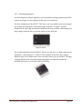
3.3.2. Transceiver Selection
Due to time constraints of the project and the availability of VHF transceiver modules,
our team decided to consider only VHF transceiver modules instead of trying to build our
own transceiver. We considered three different modules: Radiometrix UHX1, Melexis
TH7122, and Analog Devices ADF7021.
Radiometrix UHX1 operated at a frequency of 140 to 175 MHz and allowed output
power of 1 mW to 500 mW. It used FM modulation with channel spacing of 12.5 and 25
kHz. The temperature rating on the device was from -30 to 75 °C. With the temperature
only going down to -30 °C, choosing to use the 216 to 220 MHz band, and a cost of
$266, this transceiver was not a valid option
Melexis TH7122 transceiver allowed frequency range of 27 to 930 MHz. It is digitally
programmable with modulation schemes of FSK, FM, and ASK. The chip has an
adjustable output power of -20 to 10 dBm which means that an external power amplifier
Wireless Bear Tracking, Group May1010
Page 30
would be needed to achieve an output power of 1 watt. The transceiver has an operating
temperature range of -40 to 85 °C and can transmit at a data rate as low as DC with
external components and as high as 20 kbps. Narrowband operation required more
external components to improve performance. TH7122 had a sensitivity of -107 dBm and
had a cost of $13.40.
The last transceiver we considered was Analog Devices ADF7021. The ADF7021 had a
frequency range of 80 to 950 MHz. It is digitally programmable with modulation
schemes of FSK, 3FSK, 4FSK, and MSK. The chip has an adjustable output power of -16
dBm to 13 dBm which means that an external power amplifier would be needed to
achieve an output power of 1 watt. The transceiver has an operating temperature range of
-40 to 85 °C and can transmit at a data rate of 50 bps to 32.8 kbps without any external
components. The transceiver is designed as a narrowband transceiver with programmable
bandwidths of 12.5, 18.75, and 25 kHz. ADF7021 has a receiver sensitivity of -130 dBm
at 100 bps with on-chip image rejection calibration. It also had an on-board temperature
sensor and battery strength indicator.
We decided to use the Analog Devices ADF7021. It required fewer external components
compared to the Melexis TH7122. It also came with software that helped design the
component values of the external circuitry, performed simulations of the chip, and gave
register values to be programmed into the ADF7021 all based on our frequency, external
oscillator frequency, and bandwidth. The chip was also the cheapest at $5.76.
3.3.3. Detailed Design
The following section describes the detailed design for the VHF transceiver. This
includes diagrams, schematics, and simulation data.
3.3.3.1.
VHF Overview
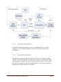
The Analog Devices ADF7021 transceiver performs the modulation and
demodulation of the data sent from the microcontroller. ADF7021 outputs the
modulated data at a digitally programmable power range of -16 dBm to 13 dBm to an
external power amplifier SPA-1118 made by RFMD. This power amplifier has a
fixed gain of 17.2 db and an output power at 1db compression of 29.5 dBm. SPA1118 outputs to RF switch SKY13270-92LF made by Skyworks which connects the
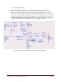
RF output and RF input to a single 50 ohm antenna. For a block diagram, see Figure
5.
Wireless Bear Tracking, Group May1010
Page 31
Figure 5. System Block Diagram
3.3.3.2.
VHF Transceiver ADF7021
The ADF7021 has been configured to have a bandwidth of 25 kHz, a carrier
frequency of 217.025 MHz, transmit at a data rate of 300 bps, and use FSK
modulation.
3.3.3.3.
Microcontroller Interface
The data to be transmitted and received by the transceiver is interfaced with the
USART of the microcontroller. The transceiver’s registers are configured by the
microcontroller’s USART. The transceiver has three lines (VHF_CE, VHF_SWD,
and VHF_MUXOUT) that interface with the general I/O of the microcontroller. A
description of each line can be seen in Table 1.
Wireless Bear Tracking, Group May1010
Page 32
3.3 V is high and 0 V is low
VHF_TX
VHF_RX
VHF_SCLK
VHF_WRITE
Transceiver
ADF7021
VHF_READ
VHF_SLE
VHF_CE
VHF_SWD
PIC
VHF_MUXOUT
ANT_CTL0
RF Switch
ANT_CTL1
SKY13270-92LF
Figure 6. Interface of Transceiver and RF Switch to Microcontroller
Table 1: VHF to PIC I/O Descriptions
VHF_TX
VHF_RX
VHF_SCLK
VHF_WRITE
VHF_READ
VHF_SLE
VHF_CE
VHF_SWD
VHF_MUXOUT
ANT_CTL0
ANT_CTL1
Serial data that is sent to be transmitted
VHF received data from another device
Serial clock input for writing and reading to the registers of the transceiver
Serial data input, data to be loaded into the registers of the transceiver
Serial data output, register data of the transceiver
Load enable input, set high to load data into register
Chip enable, low puts transceiver in power-down and register values are lost
Sync word detect, high when a match for the sync word sequence found
Digital pin that can be set to read various set conditions. Default is
Regulator_Ready – pin is set high when the regulator is ready on power up
Antenna Control bit 0 of the antenna switch. Set 0 for TX and 1 for RX
Antenna Control bit 1 of the antenna switch. Set 1 for TX and 0 for RX
Wireless Bear Tracking, Group May1010
Page 33
To write to the transceiver’s register, the data is read in on the rising edge of the
VHF_SCLK. The registers are 32 bits in length and are fed in most significant bit
to least significant bit. During this time VHF_SLE must be held low. After the
last bit rising clock has been read in, VHF_SLE must be raised high for at least 20
ns to move the data into the registers. Table 2 and Figure 7 below from the
ADF7021 datasheet show the timing requirements.
Table 2: Timing Table for ADF7021 (Analog Devices, 2009)
Figure 7. Timing Diagram for Writing to ADF7021 Registers (Analog Devices)
Readback from the ADF7021 can be performed to read back the follow seven
values: AFC, RSSI, battery voltage, temperature, external ADC, filter bandwidth
calibration, and silicon revision. To read back this data, the readback enable bit in
register 7 must be set to 1. VHF_SLE must go high to write the data to register 7.
The data appearing one clock cycle after VHF_SLE goes high must be ignored.
After this ignored clock cycle, the valid data will appear starting with the most
significant bit (bit 15). After bit 0 has been read, one clock cycle should pass
before setting VHF_SLE low to allow for the SREAD pin to be set back to
tristate. Figure 8 below from the datasheet shows the timing for readback.
Wireless Bear Tracking, Group May1010
Page 34
Figure 8. Timing Diagram for Readback (Analog Devices)
Data to be transmitted is sent on VHF_TX and data received is received on
VHF_RX. These lines are asynchronous and will be sent at the bit rate set in the
transceiver.
3.3.3.4.
Programming after Initial Power-Up
After VHF_CE is brought high, the registers in the transceiver must be reprogrammed.
Figure 9 and Figure 10 are the suggested programming sequences for transmitting and
receiving from the ADF7021 datasheet.
Wireless Bear Tracking, Group May1010
Page 35
Figure 9. Transmit sequence after power up (Analog Devices, 2009)
Wireless Bear Tracking, Group May1010
Page 36
Figure 10. Receive sequence after power up (Analog Devices, 2009)
Wireless Bear Tracking, Group May1010
Page 37
3.3.3.5.
Automatic Sync Word Detection
The ADF7021 can be set to detect a user defined sync word which can be 12, 16, 20,
or 24 bits long. When the transceiver detects the defined sync word, VHF_SWD is set
high.
3.3.3.6.
Loop Filter Design
The loop filter design from pin 1 to pin 42 was designed using Analog Devices’
software ADIsimSRD Design Studio. This software takes the user inputs of
frequency, bandwidth, and crystal oscillator frequency and automatically calculates
the values of the loop filter.
3.3.3.7.
Crystal Oscillator Design
The crystal oscillator frequency was chosen based on the SRD ADIsimSRD Design
Studio. This crystal frequency allowed the transceiver to have the exact carrier
frequency of 217.025 MHz and a bandwidth of 25 kHz. The crystal oscillator
frequency was also chosen because it was an available crystal to buy and gave us the
exact carrier frequency when multiplied internally. The crystal that was chosen is
made by Citizen and has a temperature range of -40 to 85 °C and a load capacitance
of 18.0 pF. Two capacitances were needed to be put in shunt with the crystal
oscillator to achieve the 18.0 pF load capacitance. The value of these two capacitors
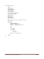
(C1 and C2) can be approximate using the following formula.
CL
C1 C 2
Cstray
C1 C 2
C1 and C2 are the load capacitors. CL is the load capacitance specified in the crystal’s
datasheet and Cstray is the total parasitic capacitances on the crystal. Cstray was
estimated at 5 pF. Using this value of Cstray and the available capacitor values
available for purchase, C1 and C2 were picked to be 20 and 36 pF.
3.3.3.8.
Matching Network
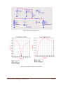
The RF output of the transceiver was matched to 50 ohm load impedance. From the
application notes, the input impedance at 220 MHz can be modeled as 159.75 +
j53.16. Using the high pass matching network that was suggested, the capacitor and
inductor values were found as shown in Figure 11. A 100.0 pF capacitor was placed
in shunt with the 3.3 voltage supply to prevent the RF from propagating to the voltage
supply. The simulation of the matching network can be seen in Figure 12. As one can
see, the reflected power at 217 MHz is -40 db.
Wireless Bear Tracking, Group May1010
Page 38
Figure 11. RF Output Matching Network
Figure 12. RF Output Matching Network Simulation
Wireless Bear Tracking, Group May1010
Page 39
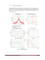
The RF input of the transceiver was matched to 50 ohms. From the application
notes, the input of the transceiver was modeled at 220 MHz. Using the suggested
matching network and the approximate values for a matching network at 150
MHz, the matching network was able to be tuned to get a match to 50 ohms. The
matching network (C3, C4, L2, and L3) can be seen in Figure 13. Simulating the
circuit (see Figure 14), the reflected power was -51 db at 217 MHz with an input
impedance of 50.182 + j0.215.
Figure 13. RF Input Matching Network
Figure 14. RF Input Matching Network Simulation
Wireless Bear Tracking, Group May1010
Page 40
3.3.3.9.
ADF7021 Simulation
Using ADIsimSRD Design Studio provided by Analog Devices, simulations were
performed to simulate the performance of the transceiver's output using the values of
the loop filter, oscillator, and 50 ohm load. The results of these simulations can be
found in Figure 15.
Figure 15. ADF7021 Simulations
Wireless Bear Tracking, Group May1010
Page 41
3.3.3.10.
External Power Amplifier
The output from the ADF7021 is fed into an external power amplifier made by
RFMD (SPA-1118). This external power amplifier amplifies the power by 17.2 dB
and has a 1 dB compression of 29.5 dB. The matching network and bias network was
supplied by RFMD. The values of the external components were optimized for a
frequency of 240 MHz and are matched to 50 ohms. The application engineer from
RFMD suggested starting with the values and then slightly adjusting them once the
board is built to achieve an optimal match.
3.3.3.11.
RF Switch
A RF switch connects the output RF of the external power amplifier and the RF input
of the transceiver to the common antenna. The RF switch is made my Skyworks
(SKY13270-92LF). The switch has a 0.1 db compression point of 37 dBm and can
handle up to 6 watts of power. The switch isolates the high power transmission from
the RF input of the transceiver. The isolation helps prevent any damaging to the RF
input of the transceiver.
ANT_CTL0 and ANT_CTL1 are the control lines from the microcontroller.
shows the control lines settings for transmitting and receiving.
Table 3: RF Switch Control Lines
Transmit
Receive
ANT_CTL0
1
0
ANT_CTL1
0
1
3.4.VHF Antenna
The antenna design at the collar and base station is very important in order for the signals to
be transmitted at the distances necessary for the bear tracking system. The collar and the
routing unit will both have different antenna types and styles due to the different restrictions.
The combination of the two antenna types should have a transmission distance in the wooded
landscape of nearly five miles.
The antenna at the collar is very restricted in size and shape. The antenna must fit on the
collar and be able to withstand the bear’s abuse. The antenna should be sewn into the collar
as much as possible, and if it protrudes, it must be very minor as to avoid damage by the
bears. Curvature of the antenna around the collar and proximity to the bear will greatly affect
the performance of the antenna.
Wireless Bear Tracking, Group May1010
Page 42
The router antenna can be much more sizable which will also allow for a larger antenna gain.
It is necessary in order to receive the signals sent by the collar antenna which may be
restricted due to different obstructions. It can be assumed that the router will be placed in a
relatively clear and higher elevated location.
Wireless communication can be summed up in the following equation, sometimes called the
link equation, or link budget equation.
The PT and PR are the power transmitted and the power received. GT and GR are the gain of
the transmitting and receiving antennas. Note that this is not in dB, but is a direct ratio of the
max directional gain of the antenna. λ is the wavelength of the transmitted signal and R is the
distance between the two antennas.
In this system, due to the poor gain of the antenna on the bear collar, the antenna gain for the
router antenna will have to be much higher. The following describes several different antenna
types and then the detailed design will incorporate the final selection of collar and router
antenna.
3.4.1. ¼ Wavelength Whip Antenna
The ¼ wavelength whip antenna would enter the unit under the neck of the bear and wrap
around the bear’s neck stitched into the collar. At the defined frequency of 217 MHz, the
length of this antenna would be approximately 12.07 inches. This would wrap around the
bear’s neck stitched into the collar and slightly protrude near the top of the collar.
The monopole antenna would require a large ground plane, which the small unit may not
be able to provide. The large ground plane is the reference for the signals that will be
transmitted to the antenna. It will be necessary in this situation to have an entire ground
plane on the printed circuit board.
The antenna would be connected directly to the transceiver. This antenna would not
require any transmission line, but the entire wire connecting the antenna to the transceiver
will act as part of the antenna. Other signals will need to be shielded from this antenna
portion.
Wireless Bear Tracking, Group May1010
Page 43
The antenna extended along inside the collar will be made from stranded steel aircraft
cable. This is a similar material to other wildlife telemetry antennas. There are several
different types of aircraft cable, but the most important quality is thickness. The stranded
cable allows for it to be flexible as it wraps around the neck. The diameter of the cable
must be wide enough to account for the bandwidth of the signal. As the cable of the
antenna widens, the higher bandwidth capability of the antenna will increase.
Figure 16. Example Whip Collar Antenna(Advanced Telemetry Systems)
Pros
Antenna is easily made
Very inexpensive
Very flexible around the neck of the bear
Does not protrude out of the collar
Can match the impedance with discrete components
Cons
Antenna is not shielded properly and will also accept a lot of noise
The curvature of the antenna will not allow for the ground plane to be
perpendicular to the antenna and possibly allow interesting results
Research has shown that the ground plane should be several wavelengths long to
produce a stable impedance input
Wireless Bear Tracking, Group May1010
Page 44
3.4.2. ½ Wavelength Whip Antenna
This antenna is very similar to the ¼ wavelength, except it will have a much longer
physical length. This increase in length will also allow a higher antenna gain. The
increase in length will also be more cumbersome for the bear to fit in the collar.
Pros
Antenna is easily made
Very inexpensive
Very flexible around the neck of the bear
Has a high antenna gain compared to the ¼ wavelength antenna
Can match the impedance with discrete components
Cons
Antenna will protrude out of collar and be subject to damage by the bears
Antenna is not shielded properly and will also accept a lot of noise
The curvature of the antenna will not allow for the ground plane to be
perpendicular to the antenna and possibly allow interesting results
Research has shown that the ground plane should be several wavelengths long to
produce a stable impedance input
3.4.3. Sleeve Dipole Antenna
The sleeve dipole antenna is the solution to the unwanted noise possibilities involved in
an unshielded whip antenna. A conductive sleeve surrounds the coaxial transmission line
for a certain portion of the antenna. The conductive sleeve then connects to the outer shell
of the coaxial transmission line and the inner conductor continues as the antenna.
The length of outer conductor, diameter of the conductor, and type of dielectric in
between the coaxial transmission line and this conductor all affect the antenna. This
sleeve works to filter out unwanted frequencies.
Wireless Bear Tracking, Group May1010
Page 45
The sleeve dipole antennas available have mostly a hard metal sleeves which make it
difficult to wrap around the neck of the bear. Also, the researched designs include the
total length to be around ½ wavelength, which is difficult to keep contained inside of the
collar.
Figure 17. Sleeve Dipole Antenna(Saunders and Aragon-Zavala)
Pros
Antenna is inexpensive
More reliable impedance matching than alternative antennas
Coaxial transmission line will give more accurate results
Has a high antenna gain compared to the ¼ wavelength antenna
Cons
Antenna will protrude out of collar and be subject to damage by the bears
The curvature of the antenna will not allow for the ground plane to be
perpendicular to the antenna and possibly allow interesting results
Antenna is difficult to make and more expensive than alternatives
Antenna sleeve length and style is difficult to measure and calculate
3.4.4. Normal Mode Helical Antenna
A helical antenna is a coiled antenna that allows the antenna size to be compressed. The
electrical length of the antenna is still half wavelength, but the physical length of the
antenna is much less than that. This antenna in the normal mode will radiate out normal
to the axis of the antenna. It operates in normal mode when the diameter of the antenna is
much less than that of the wavelength of the receive signal.
Wireless Bear Tracking, Group May1010
Page 46
This antenna would be incorporated into the collar and possibly directly into the unit
itself. It would be difficult to keep the antenna oriented in the correct direction due to its
size.
Pros
Antenna is inexpensive
Size is much smaller than other antennas
Has a high antenna gain compared to the ¼ wavelength antenna
Impedance can be matched using discrete components
Cons
The ground plane will not be directly perpendicular to the antenna which may
lead to interesting results
Antenna is not available in size from a manufacturer
Difficult to manufacture uniform antennas for collars
Difficult to orient antenna on collar for maximum reception
3.4.5. Rotating Directional Antenna
The previous antennas have been designed for use on the collar. The following antennas
will be of use on the router unit. These antennas will need to have much higher gain and
therefore will not be omnidirectional. The directional antenna allows there to be higher
gain over a more condensed area, yet it is necessary to receive signals from all directions
as bear can be traveling at any position.
One option is to build a highly directional antenna and have it rotate to pick up signals in
all directions using a small motor. This would allow there to only be one antenna on the
router with high gain and it would receive from all directions horizontally.
Pros
Antenna is very directional and has high gain
There will be less antenna components than other router antennas
Cons
The motor will allow for more possibilities of mechanical failure
The motor will consume battery
The rotation of the antenna may possibly miss signals when they are sent
Wireless Bear Tracking, Group May1010
Page 47
3.4.6. Helical Antenna Array
Instead of a rotating antenna, several directional antennas can be set up with their
antennas connected in parallel. One simple directional antenna is a helical antenna.
Above the helical antenna was used in normal mode as a possible collar antenna. Here the
helical antenna will be used in axial mode because the diameter of the loops (shown as
variable D in Figure 18) will be much larger than the wave length of the transmitted
signal.
Figure 18. Helical Antenna (Burberry)
The radiation pattern for each instance of the helical antenna will overlap so that in all
directions horizontally there is a high gain pattern. Typical gains for Axial Mode Helical
antennas are between 10 and 15 dB compared to an isotopic radiator. The radiation
pattern is very narrow which will contribute to several antennas necessary for the array.
Pros
Antenna is relatively inexpensive and can be hand made
Has a very high gain up to 15 dB
Impedance can be matched using discrete components
Cons
The antenna has a very narrow aperture and will require several antennae to build
an effective array
The axial mode antenna are difficult to support especially in harsh climate
Wireless Bear Tracking, Group May1010
Page 48
3.4.7. Yagi Antenna Array
An antenna array can be made similar to the helical antenna described above, but it can
be made with a Yagi antenna. A Yagi antenna consists of a simple dipole antenna, along
with several conducting directing elements and a reflecting element. The Yagi antenna
can vary in gain based on the length of the elements and the number of elements, but
Yagi antennae consistently can have gains for 8 to 11 dB. More antenna elements will
increase gain, but also decrease directivity, resulting in more antennas necessary to cover
the pattern (Burberry).
The Yagi Antenna can be constructed out of very simple materials including conducting
rods and PVC or other plastic tubing. Below is an example of a Yagi antenna.
Figure 19. Six Element Yagi Antenna(Setian)
Pros
Antenna is inexpensive.
Antenna can be easily constructed.
Gain is higher than most antennas, can be as high as 11 dB.
Antenna will withstand the harsh environmental conditions.
Impedance can be matched using discrete components
Cons
High gain is achieved at the cost of directivity.
Antenna may consist of several different components.
Wireless Bear Tracking, Group May1010
Page 49
3.4.8. Detailed Design
The bear communication solution will consist of a ¼ wavelength whip antenna and a
Yagi antenna array solution.
The ¼ wavelength antenna will constructed from a coaxial cable with the outer casing
stripped back. The inner wire left exposed will be equal to approximately ¼ wavelength
of the transmitted signal. The coax can be then directly mounted to the PCB with the
appropriate connector. The PCB will need to be a 4 layer board in order to receive the
necessary grounding capabilities for the best antenna performance.
The router antenna will be the Yagi antenna because of its easy of construction and
ability to better withstand the elements than the axial mode helical antenna. There will be
three or more element Yagi antennas and just as many separate antennas in the system in
order for the antenna to view all directions.
Using the link budget equation at the beginning of this section we can determine the
amount of power that will be delivered to the router from a bear.
In the system that we will use, the PT will be equal to 1 Watt. The GT is the gain of the
ideal omnidirectional whip antenna, which by definition is 1. The GR is the gain of the
router antenna, which we will estimate to be 10 dB or a numerical gain of 3.2. The
wavelength at 217 MHz is 1.38 meters. We will assume that the distance needed to
transmit is about 8 km. A compensation factor of ½ is placed in the equation as well to
account for terrain and tree obstructions.
At the baud rate of the system, the receiver can sense at levels down to -130 dBm or 1E16 Watts. The received power, even with the compensation factor, is much above the
transceiver’s ability to receive.
Wireless network propagation simulation software called Radio Mobile is available free
online and used by many amateur network designers to test the connections and
transmission characteristics of the wireless signals. This software uses a model for radio
propagation called the Longley-Rice model. The software allows land cover and
elevation data to be mapped in the system and simulate the actual terrain for the devices.
Wireless Bear Tracking, Group May1010
Page 50
The area of land that the bears will travel, between Ely and Tower, Minnesota is loaded
into the program along with the characteristics for the router antenna and the collar
antenna. The calculated radiation pattern, antenna gain, line loss, transmission power, and
antenna sensitivity all factor in to the outcome of this model. Figure 20 below shows the
map of the terrain and then three units. Two of the units are to simulate bears, and the
third unit will simulate the router. In Figure 21 you can see the Router unit transmit its
signal and you can see that in this simulation, the coverage of one router unit nearly
covers the entire area at one watt of transmission.
Figure 20. Radio Mobile Area of Concern
Wireless Bear Tracking, Group May1010
Page 51
Figure 21. Radio Mobile Router Station Propagation
3.5.GPS Module
The GPS Module chosen was the Ublox NEO-5Q. This was chosen because of its ‘kickstart’
weak signal acquisition technology, its compatible I2C interface, its package size, its low
power modes, and lower cost due to Digi buying in bulk.
Other modules were considered including the Trimble Copernicus and Trimble Condor.
Neither the Copernicus nor the Condor had an I2C interface, and both were larger packages
than the Ublox. The Trimble units did, however, trump the Ublox module in accuracy, update
frequency, tracking mode power consumption. These features were only slightly better than
the Ublox, and thus expendable. Overall, the Ublox NEO-5Q was a much more suitable
choice.
3.6.GPS Antenna
Unlike the VHF antenna, only one GPS antenna solution is necessary. While both bear
collars and routers will require GPS antennas, the each will be receiving GPS information in
similar conditions and restrictions.
Wireless Bear Tracking, Group May1010
Page 52
The antenna will:
Receive GPS data through thick cover of forestry
Appropriate sizing constraint to fit inside device casing
Low cost
Durable in conditions seen in Northern Minnesota
3.6.1. GPS Helix Antenna
A GPS helix antenna provides the best performance out of all GPS antennas. This is
especially true when tracking satellites near the horizon when the GPS antenna is facing
up into the sky. Unfortunately, in order to get this type of performance, the helix antenna
requires a large amount of space to get the correct wavelength for GPS signals. In our
case, the size required and space it takes up exceeds what we are hoping to fit inside of
our case. The base of the helix antenna is greater than 40 centimeters in length, the
circumference of the helix antenna is 19 centimeters, and the height is nearly 40
centimeters as well. While one of these would be simple enough for us to build ourselves,
the sizing of the unit exceeds our devices sizing constraint. (Gulley)
3.6.2. Passive GPS Patch Antenna
In an effort to try to keep costs low, the next possibility for a GPS antenna was the
passive GPS patch antenna. With this solution, we could either design and build our own
again, or buy one from another manufacturer. The advantage of the passive GPS patch
antenna is that no additional power is used in locating and getting a fix on GPS satellites.
The disadvantage of a passive antenna versus an active antenna is that it can take longer
to find the GPS satellites, requiring the device to be powered on longer and therefore
using more power anyway.
While a passive GPS patch antenna would be simple to design and print on to a printed
circuit board, it requires a larger size because the dielectric material is air. Most
manufacturers use a different dielectric material in order to reduce the size of the antenna.
Therefore it would be beneficial to use a manufactured GPS antenna unit rather than an
antenna we would build ourselves. The cost of purchasing an antenna is less than $15 per
unit. Going with a purchased unit would also save time and money invested in creating a
do-it-yourself type of antenna. (Mehaffey)
Wireless Bear Tracking, Group May1010
Page 53
3.6.3. Active GPS Patch Antenna
Since a manufactured passive GPS patch antenna was already being considered, we also
looked at purchasing an active GPS patch antenna. Research showed that active GPS
antennas have the same physical dimensions as passive GPS antennas. Even with this
same size, since they are powered they can locate satellites quicker than their passive
counterparts. They can also track satellites better through the dense forestry that the bears
in Northern Minnesota habitat. Even with the advantages of the active GPS patch
antenna, the cost is the same as the passive GPS patch antenna; also less than $15 per
unit.
3.6.4. Detailed Design
The active GPS patch antenna was chosen because of its theoretical ability to receive
GPS satellite signals through the dense foliage cover in the Northern Minnesota forestry.
Also it will be cheaper and less time consuming to purchase an antenna rather than
researching, designing, and building our own antenna. Taoglas is a reputable GPS patch
antenna manufacturer, which produces both active and passive GPS antennas. After
communicating with a representative of the company, it was determined that the Taoglas
AP25b would be the best antenna for our device. This antenna is only 35 millimeters
square, with a thickness of 4.5 millimeters. It also has a gain of 16 dB. This antenna also
comes with a coaxial cable connection. This will be able to connect directly to a
connection on the GPS chip that we will include.
3.7.Microcontroller
Several types of controllers were considered, but PIC was chosen over others such as Atmel
or a processor because of the great combination of versatility and ease of use.
The microcontroller chosen was the PIC18F46J11. This basis for this choice was its low
power features, multiple communication ports, large program memory, I/O count, and price.
It is an 8-bit microcontroller of the PIC18 family. 16-bit and 32-bit controllers were
considered, but it was found that 8-bit would be sufficient. Choosing 8-bit restricted the
choices to the PIC 10, 12, 16, and 18 families. There were several controllers among these
families that suited the needs of the application, but there were limited availabilities. The
controllers that were best suited and readily available were among the PIC18 family. The
PIC18F46J11 was found to meet all essential needs with the exception of EEPROM. This
was compensated for by selecting an external EEPROM chip 24FC512, manufactured by
Microchip.
Wireless Bear Tracking, Group May1010
Page 54
C programming was chosen again due to versatility and ease of use. There are other easier
languages to use such as PICBASIC, but it would limit the functionality of the controller as
well as efficiency. There are more efficient, low-level languages that could have been
chosen, such as assembly, but using this would complicate the programs needed to be written
far too greatly.
3.8.Chassis
The chassis took into account a number of parameters in choosing the optimal solution. The
chassis needs to be able to withstand the rugged environment (i.e. shock and vibe,
waterproof, temperature) as well as the bears themselves. We were informed that the bear
cubs tend to chew on the collars during the hibernation time. Therefore, we needed an
encapsulation that was small enough but could still endure the effects of its use as well as one
that could contain circuitry without having any effect on the circuit’s performance.
3.8.1. Commercial Cases
These plastic cases are meant to hold cell phones, wallets, and cameras. Their focus is for
personal use for protection of the users valuables.
Pros
•
•
•
•
•
Waterproof
Crushproof
Buoyant Case
Environmentally friendly
Cheap
Cons
• Dimensions and layout aren’t customizable.
• Simple latch for closing
Wireless Bear Tracking, Group May1010
Page 55
3.8.2. Industrial Cases
These polycarbonate cases meet industry standards and are meant for housing electronics.
Pros
•
•
•
•
•
•
Waterproof
Buoyant case
Customizable shape and layout.
Premade cases
Environmentally friendly.
Cheap
Cons
• Unknown lead time if customized design
3.8.3. Detailed Design
The industrial cases were chosen because of their required fulfillment of industry
standards. The cases meet National Electrical Manufacturers Association (NEMA)
standards 1, 2, 4, 4x, 12, and 13. These standards are shown in Table 4.
Standard
NEMA 1
NEMA 2
NEMA 4
NEMA 4X
NEMA 12
NEMA 13
Description
Enclosures constructed for indoor use to provide a degree of protection to personnel
against incidental contact with the enclosed equipment and to provide a degree of
protection against falling dirt.
Same as NEMA 1 including protection against dripping and light splashing of liquids.
Enclosures constructed for either indoor or outdoor use to provide a degree of protection
to personnel against incidental contact with the enclosed equipment; to provide a degree of
protection against falling dirt, rain, sleet, snow, windblown dust, splashing water, and
hose-directed water; and that will be undamaged by the external formation of ice on the
enclosure.
Same as NEMA 4 including protection against corrosion.
Enclosures constructed (without knockouts) for indoor use to provide a degree of
protection to personnel against incidental contact with the enclosed equipment; to provide
a degree of protection against falling dirt; against circulating dust, lint, fibers, and flyings;
and against dripping and light splashing of liquids.
Enclosures constructed for indoor use to provide a degree of protection to personnel
against incidental contact with the enclosed equipment; to provide a degree of protection
against falling dirt; against circulating dust, lint, fibers, and flyings; and against the
spraying, splashing, and seepage of water, oil, and non-corrosive coolants.
Table 4: Nema Case Standards (Computer Dynamics)
These cases can also be equipped with heavy duty waterproof prevention options. This
will ensure no intrusion of water. Also, because they are composed of polycarbonate they
have a very high tolerance to impact and wear over time.
Wireless Bear Tracking, Group May1010
Page 56
3.9.Power Supply Circuitry
The power supply section will take the power from the battery and allow it to be readily
available to all components in the system at the power allowances necessary. Table 5 shows
the components in the unit and the power requirements for each of these components.
Component
Maximum Required Current
Required Voltage
PIC microcontroller
15 mA
3.3 V
UBLOX GPS Module
80 mA
3.3 V
Analog Devices
Transceiver
23.5 mA
3.3 V
Power Amplifier
330 mA
5V
Table 5: Power Requirements
Essentially, after much research it was decided that four AA batteries would serve as the
input to three high efficiency buck converters. These step-down regulators would be used to
provide the 5V and two 3.3V power lines. A tap directly on the 6V output would be stepped
down with a voltage divider whose output would serve as the input to an A/D converter on
the PIC18F46J11. This voltage tap would provide for low-battery detection.
Several voltage regulators were considered for the power supply circuitry. This subsection
will describe the different types and models considered as well as the chosen solution.
3.9.1. Linear Regulators
Initially, linear regulators were considered. Specifically, the LM317 was the linear
regulator of choice. This regulator provided the required current, allowed for a large input
voltage range, was adjustable for a large output voltage range, and was readily available.
It was unfortunately very inefficient and thus dismissed as an option.
Figure 22. LM317
Wireless Bear Tracking, Group May1010
Page 57
3.9.2. Switching Regulators
In researching more efficient regulators, it was found that switching regulators should be
used in our design. Several regulators of this type were considered.
The first considered was the LM2717. This device was very suitable as its current output
was beyond the requirement, it had a dual output such that 3.3V and 5V could be
obtained on the same chip, and separate shutdown pins were available. Unfortunately, the
input voltage needed to meet our current output was not sufficient.
Figure 23. LM2717
The second considered was the MAX863. This device also gave very high output current
capabilities, a dual output of 3.3V and 5V were available on the same chip, separate
shutdown pins were available, and even a low-battery detect pin was provided. The input
voltage needed to meet our current output requirement was again the problem the
downfall of this part, as well as the lack of availability.
Figure 24. MAX863
Wireless Bear Tracking, Group May1010
Page 58
The third and chosen solution was the ADP3050 series. These step-down buck converters
are available in 3.3V and 5.0V fixed outputs which are both used in the design. Both
permit very wide input rages, separate shutdown pins were available, and the input
voltage allowed current outputs well above the requirement. These devices also required
very little external circuitry and are readily available, unlike the previously considered.
Figure 25. ADP3050
3.9.3. Detailed Design
The chosen design is based around an ADP3050 step-down buck converter. Three of
these are used, one for the 5V output and two for the 3.3V output.
3.9.3.1.
General Circuit
The circuit to be used with the ADP3050 is the fixed output version. The applications
information suggests the following circuit. This general circuit will be used in the
design but the specific values shown below in Figure 26 are not necessarily the same.
Figure 26. ADP3050 General Circuit
Wireless Bear Tracking, Group May1010
Page 59
3.9.3.2.
Switching Inductor and Output Capacitor Choice for GPS Unit
The GPS unit requires an input of 3.3V with a maximum ripple voltage of 50mVPP.
Thus, the switching regulator must be designed to meet these conditions. To be safe,
the regulator was designed such that the output ripple voltage is 25mVPP. For the
ADP3050, the output Vripple depends on the inductor value chosen as well as the
ESR of the output capacitor. The equations for this are the following:
where L is the inductor value chosen, Vin is the input voltage, Vout is the output
voltage, fsw is the switching frequency (fixed at 200kHz for this device), ESR is
the effective series resistance, Vripple is the output ripple voltage, and Iripple is
the output current ripple.
For the 3.3V step-down design, the input voltage is 1.5V*4 = 6V, the output
voltage is 3.3V, and the switching frequency is 200kHz. Using MATLAB, the
ESR of the output capacitor was plotted as a function of inductor choice. The
code and output are below in Figure 27.
Vin = 6;
fsw = 200e3;
L = [0:1e-6:100e-6];
Vout33 = 3.3;
Iripple33 = ((Vin Vout33)./L).*(1/fsw).*(Vout33/Vin);
ESR33 = 25e-3./Iripple33;
plot(L,ESR33)
xlabel('Inductor Value (uH)'),
ylabel('ESR (Ohm)')
Figure 27. 3.3V ESR Calculations
Wireless Bear Tracking, Group May1010
Page 60
From the graph above, it is shown that selecting a 22uH inductor will result in the
choice of capacitor having an ESR of about 74mΩ. After much research it was
found that the best choices were a 22uH inductor and a 100uF tantalum capacitor
with 75mΩ ESR. Using these values, the new Vripple is:
The inductor chosen must be able to handle the proper current draw. The 3.3V
supply is estimated to draw between 250mA and 300mA. For worst-case scenario,
we will assume the regulator draws 120mA. According to the ADP3050
datasheet, the inductor must be able to handle 20% more than the peak switching
current. The calculations for this are shown below.
where Isw(pk) is the peak swing current, Iout(max) is the expected maximum
output current, and Iripple is the output ripple current. After much research, it was
found that a 22uH inductor with 350mA current rating was sufficient.
The values for the passive components calculated above will be used for both
3.3V regulators.
3.9.3.3.
Switching Inductor and Output Capacitor Choice for PA
The power amplifier requires an input of 5V without a specified maximum ripple
voltage. For consistency, a maximum ripple voltage of 25mVPP. Thus, the switching
regulator must be designed to meet these conditions. The equations used previously
are repeated, and the MATLAB plot was redone using the output voltage of 5V. The
code and output for this is shown below in Figure 28.
Wireless Bear Tracking, Group May1010
Page 61
Vin = 6;
fsw = 200e3;
L = [0:1e-6:100e-6];
Vout5 = 5;
Iripple5 = ((Vin Vout5)./L).*(1/fsw).*(Vout5/Vin);
ESR5 = 25e-3./Iripple5;
plot(L,ESR5)
xlabel('Inductor Value (uH)'),
ylabel('ESR (Ohm)')
Figure 28. 5V ESR Calculations
From the graph above, it is shown that selecting a 47uH inductor will result in the
choice of capacitor having an ESR of about 282mΩ. After much research it was
found that the best choices were a 47uH inductor and a 47uF tantalum capacitor
with 300mΩ ESR.
The inductor chosen must be able to handle the proper current draw. The 5V
supply is estimated to draw up to 330mA. For worst-case scenario, we will
assume the regulator draws 120mA. According to the ADP3050 datasheet, the
inductor must be able to handle 20% more than the peak switching current. The
calculations for this are shown below.
where Isw(pk) is the peak swing current, Iout(max) is the expected maximum
output current, and Iripple is the output ripple current. After much research, it was
found that a 47uH inductor with 600mA current rating was sufficient.
3.9.3.4.
Final Power Circuit
As stated before, three regulators provide three different power lines. The +3.3V
ALWAYS line powers the Microchip PIC18F46J11 as well as the backup voltage for
the GPS unit. This line should never be shut off. The +3.3V line powers the GPS unit.
This can be shut off by the PIC when the GPS unit is not in use. The +5V line powers
Wireless Bear Tracking, Group May1010
Page 62
the power amplifier of the VHF transceiver. This can also be shut off when the power
amplifier is not in use. The resistor divider at the bottom steps down the input to 3V
so that the PIC’s A/D can monitor the voltage. When the voltage gets below 2.8V
(which means the input voltage dropped to 5.6V), the PIC will detect a low battery.
This value was chosen based on the ADP3050 datasheet. It specifies that the 5V
regulator will not supply the required current below a 5.5V input.
3.10.
Battery
The choice for battery had a lot of things to consider. It must be able to withstand the harsh
environment of the Minnesota woodlands, both terrain and climate. In addition, it must be
able to last at least 3 months without a replacement. Finally, it must be able to deliver the
required voltage to power the components.
3.10.1. Nickel Metal Hydride (NiMH)
The Nickel Metal Hydride battery is composed of a hydrogen-absorbing alloy for the
negative electrode.
Pros
•
•
•
Cons
•
•
•
High capacity.
Many recharge cycles.
Very good performance in high-drain devices.
High self-discharge rate.
Does not function well at low temperatures.
Memory effect.
Wireless Bear Tracking, Group May1010
Page 63
3.10.2. Lithium Ion (Li-ion)
A lithium ion battery is composed of a lithium anode and a carbon cathode.
Pros
•
•
•
•
•
•
•
•
Cons
•
•
•
Much lighter than other batteries.
No memory effect.
High capacity.
Very good performance in high-drain devices.
Very slow self-discharge rate.
Function better than other types at extreme temperatures.
Capable of withstanding environmental effects
Environmentally friendly.
More expensive than other types
Lower shelf life than other types
Due to high capacity, can be hazardous if short circuited
3.10.3. Detailed Design
Because environmental conditions are a huge part of the project, we decided to go with
the Li-ion battery because it has much better performance at low temperatures.
Regardless of the chosen solution, there were tradeoffs. The higher quality battery will be
more expensive; overall this will be more beneficial because of the longevity they have
over the alternatives.
Wireless Bear Tracking, Group May1010
Page 64
4. Implementation
The second semester of the project, two PCB’s were designed, populated, and tested. Our team
narrowed our focus to the hardware development and low-level programming, leaving high level
networking protocols to be implemented in the future. The following section defines the
implementation of the hardware and software used in the project.
4.1.Hardware
This section describes the assembly and implementation of the hardware, including design
changes. The basic hardware includes two populated PCB’s, two VHF antennas, one GPS
antenna, the USB interconnect, and the power cables.
4.1.1. Printed Circuit Board Layout
The PCB layout was done using Cadence Layout Plus. Each component on our board has
an associated footprint. Most of the footprints were included in the standard library but
some of the footprints had to be created manually. Because of budget constraints, we
designed a two layer PCB. For testing purposes, we kept all components on the top side
of the PCB and included extra test points and connectors.
The general strategy for the layout was to keep the VHF and GPS portions as far apart as
possible. Figure 29 shows the general layout structure of our board. Because RF
performance greatly depends on the ground plane, the PCB board has copper pour
everywhere on the board that does not have any components or traces; these areas are on
both the top and bottom layer of the PCB. To try to keep away from breaking up the
ground plane with traces, we alternated between the top and bottom layer on longer
length traces.
VHF
PIC
Power
GPS
Power
USB
Figure 29: PCB Layout Structure
Wireless Bear Tracking, Group May1010
Page 65
When starting the layout, the most attention was put on the RF portions of the VHF and
GPS section. The reason for this is because adding more traces changes the characteristic
impedances of the circuit which will result in the parts not being matched to 50 ohms. It
should be noted that on the VHF portion, we had to create two transmission lines because
we were not able to keep transceiver and RF switch as close as possible. Using Advanced
Design System’s (ADS) LineCalc and the characteristic of our PCB as shown in Table 6,
we were able to calculate that a 50 ohm transmission line had a width of 109 mils.
PCB Material
FR4
H
64 mils
Er
4.8
Mur
1
Cond
5.8x10⁷
Hu
3.9x10¹⁴
T
1.4 mils
Table 6: PCB Characteristics
Once we had the RF portions layout using the least amount of traces, we laid out the rest
of the PCB trying to make the board as compact as possible and avoid breaking up the
ground plane. Plated through holes were also added at various areas to connect the top
and bottom ground planes. We also kept all the external connecters on the same side.
Copper areas were used on each of the three buck converters to help with dissipating
heat. Using the large copper areas was suggested by the manufacturer. The transceiver
and power amplifier both have ground planes underneath of their packages which are
used for RF performance along with helping dissipate heat. We used copper areas to
make these connections. Once we had the layout done, we used Advanced Circuits
(www.4pcb.com/) to manufacture our circuit board because they have a special offer
where we can build our boards for $33 each with no minimum quantity.
It should be noted that after we made these boards, we realized that we inadvertently did
not add the solder mask layer for the power amplifier’s and transceiver’s ground pad. The
revision A PCB layout has this fixed. Also, the crystal was bigger than the package
outline. However, in the new design, the current crystal is not being used. Another
consideration in changing the layout is with the inductance of L10. By changing the
Wireless Bear Tracking, Group May1010
Page 66
lengths of the traces from L10 to the transceiver’s pins 44 and 46, the inductance value of
L10 may need adjustment (See Section 4.2.1)
4.1.2. Populated Board
All parts were ordered and soldered onto the board as shown in Figure 30.
Figure 30: Populated Printed Circuit Board
4.1.3. ADF-7021 Register Configuration
The ADF-7021 uses registers to configure it in either transmit or receive mode. There is a
sequence to follow to configure the transceiver in transmit or receive mode which can be
seen in Figure 9 and Figure 10.
It should be noted that a lot of these values are based on the current hardware, Revision
A. If the crystal oscillator is changed to a voltage controlled oscillator with a better
frequency accuracy as suggested, the register values will change.
4.1.3.1.
Transmit Mode
The following steps show the order for configuring the transceiver in transmit mode.
1. Set VHF_CE High
Setting the VHF_CE high turns on the transceiver.
2. Wait around 1.1 ms
This required delayed is necessary to allow the power regulators to power up.
VHF_MUXOUT will be asserted high when the regulators are ready.
Wireless Bear Tracking, Group May1010
Page 67
3. Write to Register 1- VCO/Oscillator Register
1
00
0011
0
1
11
00
1
0
0000
001
0001
External
VCO,
Yes
VCO
Center,
Nominal
VCO-Bias
given
from
Table 9,
0.75mA
RF
divide
by 2,
off
VCO
Enable,
ON
CPCurrent,
Set to
2.1 mA
XTAL Bias,
20uA, higher
current, faster
power up
XOSC
Enable,
Yes using
external
crystal
XTAL
Doubler,
Clock out
divide,
off
RCounter,
Address
bits
NO
Set to 1
Table 7: TX Register 1 value
The phase frequency detector (PFD) is given by the following formula based on
whether the RF divide by 2 is on or off.
(Analog Devices)
Maximizing the PFD frequency reduces the N value which will reduce the noise
multiplied at a rate of 20log10(N). The PFD frequency is used in the carrier
frequency and frequency modulation. Analog software, ADIsimSRD, also gave a
lot of the values needed based on our configuration, ADIsimSRD also suggested a
PDF frequency of 4.032 MHz.
The charge pump current was set to the highest value to have the fastest charge
rate.
4. Wait at least 0.7 ms
5. Write to Register 3- Transmit/Receive Clock Register
00 1010
0010 1000
1101 0010
0010
00
0011
AGC-CLKDivide, 10
SEQ-CLKDivide, 40
CDR-ClkDivide, 210
DEM-CLKDivide, 2
BBOS Clk
Divide, 4
Address
Table 8: TX Register 3 value
Wireless Bear Tracking, Group May1010
Page 68
Baseband offset clock frequency (BBOS CLK) must be greater than 1 MHz and
less than 2 MHz where BBOS CLK is given by the following equation where
BBOS_CLK_Divide equal to 4 gave us the desired frequency.
XTAL _ Frequency
BBOS _ CLK _ Divide
4.032MHz
1.008MHz
4
The demodulation clock needed to be set between 2 MHz and 15 MHz. The
demodulation clock is given by the following equation where a value of 2 gave us
the desired frequency.
XTAL _ Frequency
DEMOD _ CLK _ Divide
4.032MHz
2
2.016MHz
For 2FSK, the data/clock recovery frequency (CDR CLK) needs to be within 2%
of 32 times the data rate. In our case, the data rate was 300 bits/sec given a CDR
CLK of 9.6 kHz. The CDR CLK is given by the following equation where
CDR_CLK_DIVIDE needs to be a value of 210.
DEMOD _ CLK
CDR _ CLK _ Divide
2.016 MHz
210
9.6kHz
Sequencer clock (SEQ CLK) supplies the clock to the digital receiver block and
should be close to 100 kHz as possible. The SEQ CLK is given by the following
equation with a value of SEQ_CLK_DIVIDE being 40 giving us the closest value
to 100.
XTAL
SEQ _ CLK _ Divide
Wireless Bear Tracking, Group May1010
4.032MHz
100.8kHz .
40
Page 69
AGC step to settle is determined by the AGC update rate. It should be set close to
10 kHz. The AGC update rate is given by the following equation with a value of
AGC_CLK_DIVIDE of 10 given us the closest value to 10 kHz.
SEQ _ CLK
100.8kHz
10.08kHz
AGC _ CLK _ Divide
10
6. Write to Register 0- N Register
000
0
0
0011 0101
110 1010 0001 0100
0000
Muxout Regulator
Ready
UART
Mode, No =
0
Tx/Rx, TX = Integer-N,
0
53
Fractional-N, 27156
Address
Bits
Table 9: TX Register 0 value
The RF output frequency is calculated by the following equations depending on if
RF divide by 2 is set which in our case it is not set to be on.
(Analog Devices)
An Integer-N and Fractional-N value of 53 and 27,156 gives us the center
frequency of 217.0375 MHz. It should be noted that a when the Fractional-N is
used, spurs can appear on the VCO output spectrum at an offset frequency that
corresponds to the difference frequency between an integer multiple of the
reference frequency and the VCO frequency.
Wireless Bear Tracking, Group May1010
Page 70
Muxout sets the output on the VHF_Muxout line. Muxout is a digital value and
can indicate the different components shown in Table 10.
Table 10: VHF Muxout Settings
7. Wait 40 us
8. Write to Register 2- Transmit Modulation Register
0
10
0 0100 1110
10 0100
11
011
0
000
0010
Raised
Cosine
Alpha,
Default
Tx-DataInvert,
Inverted
Data
Tx-Fdev, 78
PA
output
power,
36
PABias,
11
uA
PARamp,
64
codes/
bit
PAEnable,
Off = 0
Modulation
Scheme,
2FSK
Address
Table 11: TX Register 2 value
If the power amplifier (PA) is enabled/disabled by PA_Enable, it ramps up at the
programmed rate but turns off hard. If the PA is enabled/disabled by Tx/Rx
(R0_DB27), it ramps up and down at the programmed rate. PA Ramp prevents
spectral splattering or spurs in the output spectrum. By gradually ramping the PA
on and off, PA transient spurs are minimized. Setting to 64 codes per bit which is
approximately 1/300 = 3.33 ms ramp time. Less codes per bit causes a more
gradual ramp.
PA Bias current is recommended to be 11 uA when power greater than 10 dBm is
required.
Wireless Bear Tracking, Group May1010
Page 71
The external power amplifier has a gain between 19 and 24 dB at our current
frequency with a 1 db compression point of 29.5 dBm. The internal power
amplifier is set by, writing the corresponding value seen in Table 12: PA output
power into register two.
Table 12: PA output power
The estimated power output at the SMA connector can be given by the following
equation.
Output Power in dBm = 0.467742*PA_Level + 0.7323 – Loss in Circuit in dBm
The output power should not exceed more than 29 dBm to avoid non-linearity.
The desired frequency deviation is 4.80 kHz. This frequency deviation allows us
to stay in the 25 kHz channel and allows the spectrum output to drop off. This
frequency deviation was also calculated by ADIsimSRD based on the channel
width and the baud rate. The frequency deviation is given by the following
formula from the datasheet.
(Analog Devices)
By setting TX_FREQUENCY_DEVIATION to 78, it gives us a frequency
deviation of 4.798 kHz where PFD frequency is 4.032 MHz given in Register 1.
The data is set to be inverted because in receive mode the transceiver needs to be
set to be inverted to correctly set the correlator. Thus, to have the PIC receive
non-inverted data, we are inverting the data when we send it.
9. Wait at least 3.33 ms
Wireless Bear Tracking, Group May1010
Page 72
10. Transmit Data
11. Wait 3.4 ms before power down
The delay is needed because of bit latency as shown in Table 13. A latency of 1
bit means that 1/bit rate should be waited before powering down. In this case, it is
1/300 which is 3.33 ms.
Table 13: TX Bit Latency
12. Set Register 0 - PA power down
000
0
1
0011 0101
110 1010 0001 0100
0000
Muxout Regulator
Ready
UART
Mode, No =
0
Tx/Rx, RX
=1
Integer-N,
53
Fractional-N, 27156
Address
Bits
Table 14: TX Register 0 power down value
By switching TX/RX bit to 1, the power amplifier will ramp down which will
minimize spectral splattering as explained in TX Register 2 description.
13. Wait at least 3.33 ms
This delay allows time for the PA to power down.
14. Set VHF_CE to 0
By setting VHF_CE to 0, it will turn off the transceiver.
4.1.3.2.
Receive Mode
The following steps show the order for configuring the transceiver in receive mode.
1. Set VHF_CE High
Setting the VHF_CE high turns on the transceiver.
2. Wait at least 1.1 ms
This required delay is necessary to allow the power regulators to power up.
VHF_MUXOUT will be asserted high when the regulators are ready.
Wireless Bear Tracking, Group May1010
Page 73
3. Write to Register 1 - VCO/Oscillator Register
1
00
0011
0
1
11
00
1
0
0000
001
0001
External
VCO,
Yes
VCO
Center,
Nominal
VCO-Bias
given
from
Table 9,
0.75mA
RF
divide
by 2,
off
VCO
Enable,
ON
CPCurrent,
Set to
2.1 mA
XTAL Bias,
20uA, higher
current, faster
power up
XOSC
Enable,
Yes using
external
crystal
XTAL
Doubler,
Clock out
divide,
off
RCounter,
Address
bits
NO
Set to 1
Table 15: RX Register 1 value
See Section 4.1.3.1: Transmit Mode for details.
4. Wait at least 0.7 ms
5. Write to Register 3- Transmit/Receive Clock Register
00 1010
0010 1000
1101 0010
0010
00
0011
AGC-CLKDivide, 10
SEQ-CLKDivide, 40
CDR-ClkDivide, 210
DEM-CLKDivide, 2
BBOS Clk
Divide, 4
Address
Table 16: RX Register 3 value
See Section 4.1.3.1: Transmit Mode for details.
6. Write to Register 6 - IF Fine Cal Setup
0
11
011 0011
0000 1111
0001 1111
1
0110
IR Cal
Source
divide 2,
OFF
IR-CalSourceDriveLevel,
High
IF-CalDwellTime, 51
IF-CalUpperToneDivide, 15
IF-CalLowerToneDivide, 31
Enable IF
Fine Cal
Address
Table 17: RX Register 6 value
The ADF-7021 has an intermediate-frequency (IF) bandwidth calibration which
should be calibrated on every power-up in receive mode to correct for errors in
the bandwidth and filter center frequency due to process variations. There are two
different calibrations available: Coarse and Fine Calibration. In the cases where
the receive signal bandwidth is very close to the bandwidth of the IF filter, it is
recommended to perform a fine filter calibration every time the unit powers up
which is the case in our design. IF Fine calibration is setup in Register 6 and is
started by writing to Register 5.
Wireless Bear Tracking, Group May1010
Page 74
IF_Cal_Lower_Tone_Divide and IF_Cal_Upper_Tone_Divide are given by the
following formulas.
(Analog Devices)
In our case, IF_CAL_LOWER_TONE_DIVIDE and
IF_CAL_UPPER_TONE_DIVIDE should be 31 and 15.
IF Tone calibration Time is recommended to be at least 500 µs which is given by
the following equation.
(Analog Devices)
The SEQ Clk is equal to 100.8 kHz which is given in Register 3 which makes the
IF_CAL_DWELL_TIME to be at least 51 to have at least a 500 µs calibration
time.
The total time for a fine IF filter calibration is IF Tone Calibration Time times 10
which is around 5.06 ms.
7. Write to Register 5- IF Filter Setup Register
0
0
0 0000
0
0000
00 0000
0 0101 0001
IRGainAdjustUP/DN,
IRGainAdjustI/Q,
IRGainAdjustMag,
IRPhaseAdjustI/Q,
IRIF_Filter- IF-FilterPhase- Adjust, 0 Divider, 81
AdjustMag,
1
0101
IF-CalAddress
Coarse, Do
Calibration
Table 18: RX Register 5 value
Register 5 sets up the Coarse calibration.
Wireless Bear Tracking, Group May1010
Page 75
IF_Filter_Divider is given by the following equation which a value of 81 gives us
the closest value to 50 kHz.
(Analog Devices)
IF_Filter_Adjust is automatically adjusted when the Calibration is performed.
This could be set manually if desired.
IR portion is used for image rejection calibration which can be used with an
external microcontroller to calibrate the image rejection. We are currently are not
calibrating.
8. Wait at least 5.2 ms for IF calibration
9. Write to Register 11- Sync Word Detect
0000 0000 0101 1101 1010 1011
01
01
1011
Sync byte Sequence, 0x5DAB
but must be loaded least
significant bit to most significant
bit and inverted
Matching
Tolerance- Accept
1 Error
Sync Byte
Length- 16
bits
Address,
11
Table 19: RX Register 11 value
The transceiver can be set to look for a certain sequence of bits and when this
sequence is found, the VHF_SWD is asserted high. In our application, we use the
sync word to act as a start sequence that tells us that a valid transmission is
coming. We chose a start sequence of 0xBAD5. However, in when the PIC uses
synchronous transmission, it sends the least significant bit first at 8 bits at a time.
Because of this, the transceiver must look for 0x5DAB.
The transceiver also allows for a matching tolerance which is the number of errors
in the sync word that are allowed in the detection.
Wireless Bear Tracking, Group May1010
Page 76
10. Write to Register 12- SWD/Threshold Setup Register
0001 0011
10
10
1100
Data_packet_length,
19
SWD Mode- SWD
Pin High after next
sync word for data
packet length
Lock threshold mode
– Lock threshold
after next sync word
for data packet length
Address,
12
Table 20: RX Register 12 value
The lock threshold locks the automatic frequency correction (AFC) and automatic
gain correction. We set this lock to last as long as the data packet length.
11. Write to Register 0- N Register
010
0
1
0011 0101
110 1010 0001 0100
0000
Muxout DigitalLock-Detect
UART
Mode, No =
0
Tx/Rx, RX
=1
Integer-N,
53
Fractional-N, 27156
Address
Bits
Table 21: RX Register 0 value
Digital Lock Detect indicates when the PLL has locked. When the phase error on
five consecutive cycles is less than 15 ns, lock detect is set high and remains high
until a 25 ns phase error is detected at the PFD.
See Section 4.1.3.1: Transmit Mode for details.
12. Wait 40 us
13. Write to Register 4- Demod Register
10
00 0000 0001
IFPost-DemodBW,
BW, 1
25kHz
00 0110 1010
10
Discriminator- RxBW, 106
Invert,
Invert
Data
1
001
0100
Product
DeMod
Scheme,
2FSK
Correlator
Address
Table 22: RX Register 4 value
Demodulation Scheme is set to 2FSK Correlator which is used for 2FSK and has
better performance than the Linear Demodulator for 2FSK.
Wireless Bear Tracking, Group May1010
Page 77
The Discriminator BW is given from the following equations.
,
(Analog Devices)
In our case the Demod Clk is equal to 2.016 MHz (from Register 3) and fdev is
equal to 4.80 kHz (from Register 2). Using the above equation, we get a K value
of 21 which results in a DISCRIMINATOR_BW of 106.
To optimize the coefficients of the correlator, Product and Rx-Invert must be
assigned. The value of these bits depends on whether K is odd or even. The
assignment is given in the following table.
(Analog Devices)
In our case, K and (K+1)/2 is also odd. This makes Product = 1 and RX-Invert
=0b10.
Post Demodulator BW should be set according to the following equation and
table.
(Analog Devices)
In our case, the data rate is 300 so fcutoff is 225 and with Demod clk equal to 2.016
MHz (from Register 3), we get a POST_DEMOD_BW equal to 1.
Wireless Bear Tracking, Group May1010
Page 78
14. Write to Register 10 - AFC Register
0011 0010
100
1011
1000 0010 0001 1
1010
Max-AFCRange,50
KP
KI
AFC Scaling
Factor, 2081
Address
AFC
Enable, On
Table 23: RX Register 10 value
AFC is used to remove frequency errors due to mismatches between the transmit
and receive crystals.
The AFC Scaling Factor is given by the following equation.
(Analog Devices)
In our case, the XTAL is 4.032 MHz which results in a AFC_Scaling_Factor
equal to 2081
KI equal 11 (1011) and KP equal to 4 (100) are the recommended settings to give
optimal AFC performance.
The MAX AFC correction range should be less than or equal to 1.5 IF filter
Bandwidth. From Register 4, our IF filter BW is equal to 25 kHz resulting in a
MAX AFC Correction of less than or equal to 37.5 kHz. The
MAX_AFC_RANGE is given by the following equation.
(Analog Devices)
Setting the AFC correction range at 25 kHz gives us a MAX_AFC_RANGE of
50.
15. RX Mode
16. Set VHF_CE low to power down
Wireless Bear Tracking, Group May1010
Page 79
4.1.4. Matching Networks
With the PCB design completed, we re-simulated our matching networks for the
transceiver with non-ideal parts and traces using Advanced Design System 2009. We
used models for the inductors and capacitors from Murata and Panasonic, and PCB board
characteristics given in Table 6. From these simulations, we only needed to increase L8
inductance to maintain our 50 ohm matches. Figure 31, Figure 32, Figure 33, and Figure
34 all show the circuits used in ADS and their corresponding simulations.
Figure 31: Transceiver output matching network simulation circuit with non-ideals
Wireless Bear Tracking, Group May1010
Page 80
Figure 32: Transceiver output matching network simulation with non-ideals
Figure 33: Transceiver input matching network circuit with non-ideals
Wireless Bear Tracking, Group May1010
Page 81
Figure 34: Transceiver input matching network simulation with non-ideals
4.2.Hardware Modifications
The following section defines the modifications made to the original design post PCB
fabrication, and the reasons for such modifications.
4.2.1. External Inductor L10
The frequency range of the transceiver is determined by an external inductor between pin
44 and pin 46. Figure 35 shows the RF output verses total external inductance between
pin 44 and 46 of the transceiver.
Figure 35: RF output vs. total external inductance (Analog Devices, 2009)
Wireless Bear Tracking, Group May1010
Page 82
The inductance value was given by ADIsimSRD at a value of 38.5 nH based on our
center frequency of 217.0375 MHz. We initially used an inductance value of 39 nH
(L10). However, we were only able to get a max frequency of 200 MHz, which meant we
needed a smaller inductor. In our initial design, we did not include the inductance of the
traces to get to the desired inductance of 38.5 nH. After trying different values of
inductance, a 30 nH inductor gave us the desired frequency that we need. It should be
noted that if the PCB layout is changed with respect to L10, the external inductance will
change depending on the length of the traces from pin 44 and pin 46 to L10.
4.2.2. PIC Connection to Transceiver
The PIC has two different connections to the transceiver: one for configuring the
transceiver’s registers and the other for sending and receiving data wirelessly. To
configure the transceiver’s registers, we generated our own procedure that produced the
desired sequence as explained in Section 3.3.3.3. The procedure is explained in more
detail in the transceiver software Section 4.3.2.3.6.
To send data, we used the PIC’s USART. It should be noted that the USART lines for TX
and RX to the PIC and ADF7021 were switched around in using USART 1. PIC PIN 44
should be connected to TXRXCLK Pin 35. PIC PIN 1 should be connected to
TXRXDATA Pin 34 of the transceiver. On the current revision A, we worked around this
issue by using USART 2 which can be programmed to PIC Pin 1 and 44 and this issue
has been switched in the revised schematic. Using USART 2, we configured the PIC’s
USART to act as the slave. The transceiver provides the clock to output the data on the
rising edge. More details on this can be seen in Section 4.3.2.2 and 4.3.2.3
In receive mode, we do not use the PIC’s USART. Instead, we use the transceiver’s sync
word functionality. The transceiver is programmed to look for a specific start sequence of
bits which in our case is 0x5DAB. Once the transceiver sees this sequence of bits, it sets
the VHF_SWD_INT high which tells the PIC to start to read the bits on the rising edge of
the transceiver’s outputted clock. Once the whole packet is read in, the VHF_SWD_INT
is set low until the next start sequence.
4.2.3. Transceiver External Crystal
The current crystal that was picked out has a frequency tolerance of 30ppm. The
recommended tolerance rate for narrow-band applications, which is given on page 22 of
the transceiver data sheet is to have a <=10ppm. Digikey does not stock crystasl with
these specs. However, there are voltage controlled oscillators (VCXO) that have this
specification. A possible replacement is Digikey part number 631-1068-1-ND. This
VCXO has a frequency tolerance of 1.5 ppm at frequency of 12 MHz which will still
allow us to have exactly a 300 baud rate. It should be noted that if this VCXO is used
Wireless Bear Tracking, Group May1010
Page 83
instead of the current crystal, the values in the registers will have to be changed based on
this new frequency of 12 MHz.
4.2.4. I2C
The I2C lines were used by the PIC to operate an EEPROM memory chip and a UBLOX
NEO-5Q module. Both units operated on different SCL and SDA lines so that each unit
could be debugged separately. The I2C modules are available on the PIC and code was
supplied by Microchip. However, each unit required debugging, especially the UBLOX
module.
In I2C the unit has to address the slave on the line and then wait for the slave to respond
with valuable information. The EEPROM would respond with the data stored in its
memory. The UBLOX GPS chip would respond with NMEA and proprietary UBX data
messages. The UBLOX Protocol Specifications document outlined all the data messages
and how they would be configured.
The EEPROM I2C lines were accidentally switched in the original PCB fabrication.
Jumper lines had to be soldered in order to switch the two lines. Future PCBs will be
updated to this modification.
4.2.5. Power
Coupling between the 3.3V line and an unknown source was detected; therefore, it
appeared that the 3.3V line does not fully shut down. There is a possibility that devices
which use 3.3V line may still be powered even though we prompt it to shut down.
4.2.6. Antenna
A base station antenna was never constructed due to time limitations and material cost.
However, a small whip antenna was constructed for the bear collar. This antenna
consisted of a RG 58A/U coaxial cable terminating at the unit in a 50 Ω SMA connector.
The coaxial cable’s outer conductor was stripped away for a quarter-wave antenna. At the
radiating frequency of 217.0375 MHz, this length was 34.52 cm. There was also a
quarter-wave of coax left on the cable. This cable helped to match the impedance of the
unit and lengthened the antenna for a better fit on the bear collar.
This construction also leads to a poor interface between the coaxial termination and the
radiator. This is due to the mismatch between input impedance of the quarter-wave
antenna and the intrinsic impedance of the coaxial line. Some reflection is expected in the
S11 parameter of the antenna.
Wireless Bear Tracking, Group May1010
Page 84
Figure 36. Quarter-Wave Antenna Construction
4.3.Software
The following section describes the functionality and scope of the software portion of the
project.
4.3.1. PC Code
This portion describes the mapping of GPS coordinates onto Google Maps.
4.3.1.1.
Google Mappping Code
Google Maps is a handy and user friendly tool that we thought would give the
researchers a better way to locate the bears and have a better visualization of that
location. So, using the scripting language Python, we wrote a code that will extract
the GPS data sent by the PIC and automatically launch a browser and plot those
coordinates on Google Maps. This code can be seen in Appendix 6. Initially, the set
up of the port is needed. Since we are using serial communication we were able to
implement the pySerial API. This makes it very easy to access the ports needed and
also allows us to set the various parameters.
ser = serial.Serial(port=6, baudrate=2400, bytesize=EIGHTBITS,
parity=PARITY_NONE, stopbits=STOPBITS_ONE,timeout=None, xonxoff=0,
rtscts=0, interCharTimeout=None)
The only thing that needs to be monitored is the port number. Since a computer may
already be using port 6 it may require some modifications to read from the correct
Wireless Bear Tracking, Group May1010
Page 85
port that the board is connected to via USB. In order to view the COM port being
used after plugging in the device open the Device Manager application and double
click "Ports (COM & LPT)". This will list all ports being used on your computer.
From there, the correct port number may be found and the Python code may be
updated as appropriate.
Once the GPS coordinates have been read through the port in decimal form, the
program separates the latitude and longitude coordinates with a comma. This allows
the program to distinguish the coordinates. Then, it implants the coordinates into the
basic URL structure and opens the browser to that URL.
4.3.2. PIC Code
This part of the document describes the files as well as the high level and low level
functions written for the PIC18F46J11 microcontroller for Revision A. The tools used to
program this microcontroller are the following:
IDE: MPLAB
Programmer: PICKIT2 or MPLAB ICD2
Compiler: MPLAB C for PIC18 MCUs (MCC18)
The MPLAB project currently used is the following:
TDMANetwork.mcp
4.3.2.1.
main.c
This file configures and initializes the PIC18F46J11, and serves as the skeleton for
the TDMA network.
4.3.2.1.1.
main()
This function calls the initialization functions and then runs the deep sleep handler
function. It is then decided whether the power on reset (POR) was pure, meaning
it is the first power up, or was an awake from deep sleep. Proper actions are then
taken based on the decision.
4.3.2.1.2.
activate_unit()
This function is called when the PIC has fully wakened from deep sleep. It is
where communication with the GPS, VHF transceiver, and EEPROM will take
place. This is where communication with other units will take place (one frame in
Wireless Bear Tracking, Group May1010
Page 86
the TDMA network). After all networking logic is complete, data is written to the
deep sleep save registers and the PIC goes back to sleep.
4.3.2.1.3.
maintenance()
This function performs ‘maintenance’ on the peripherals of the PIC. Its purpose is
to make sure all devices are working correctly.
4.3.2.1.4.
tx_test()
This function runs the procedure needed to put the VHF section in transmission
mode. This is used for testing purposes.
4.3.2.1.5.
rx_test()
This function runs the procedure needed to put the VHF section in reception
mode. This is used for testing purposes.
4.3.2.2.
init.c
This file contains functions that initialize communication ports, I/O ports, the
oscillator, etc.
4.3.2.2.1.
eusart2USB_remap()
This function remaps the EUSART2 pins Rx2 and Tx2 to pins 14 and 15
respectively. This allows the FTDI USB to Serial converter chip to talk to the
PIC.
4.3.2.2.2.
syc_eusart2VHF_remap()
This procedure sets up the reprogrammable pins needed VHF transmission or
reception. In TX mode, USART 2 clock and data lines are mapped to Pin 1 and
Pin 44 of the PIC respectively. In receive mode, external interrupt 1 and 2 are
programmed to Pin 4 and Pin 1 respectively. Interrupt 1 is used to detect when the
VHF_SWD_INT goes high and external interrupt 2 is used to detect the rising
edge of the receive clock of the transceiver
4.3.2.2.3.
eusart2_init()
This function initializes all registers required to communicate serial data
asynchronously over the EUSART2 module.
Wireless Bear Tracking, Group May1010
Page 87
4.3.2.2.4.
syc_eusart2_init()
This procedure initializes the synchronous transmission and reception. In
transmission mode, the synchronous USART 2 is used to send the data. The
USART is set up in synchronous and slave mode and disables transmission
interrupts. The transceiver acts as the master and outputs the clock to shift the
data out.
In receive mode, the USART is not used. Instead, the receive procedure uses
interrupts. Two interrupts are needed: one for the sync word detection and the
other for the rising edge of the transceiver clock. External interrupt 1 and 2 are
tied to the sync word detection and transceiver data clock respectively. Thus, in
receive mode, this procedure sets up external interrupt 1 and 2 to be activated on
the rising edge. External interrupt 1 is the only interrupt that is activated right
away because we do not need to start clocking in data until the start character has
been detected. Lastly, the procedure calls global_var_init which initializes the
received data array and count variables to zero.
4.3.2.2.5.
osc_init()
This function initializes all registers required for the PIC’s internal oscillator to
oscillate properly.
4.3.2.2.6.
io_init()
This function initializes all GPIO pins to be either digital or analog inputs or
outputs.
4.3.2.2.7.
vhf_init()
This procedure configures the transceiver to be in either transmit or receive mode.
The procedure contains the register values needed to be written to the transceiver.
For more information on the registers values, see Section ADF-7021 Register
Configuration4.1.3. The register values are passed to the procedure send_gpio()
which writes the values to the transceiver's registers. The for loops are added to
make the required delays as defined in Section 4.1.3.
4.3.2.3.
handler.c
This file contains functions that perform any type of data handling. This involves the
deep sleep functionality, sending eusart data, sending data via I/O ports, and other
functions for peripheral testing purposes.
Wireless Bear Tracking, Group May1010
Page 88
4.3.2.3.1.
ds_handler()
This function is called to decide whether or not the power on reset (POR) was
pure or if it was from a deep sleep wake.
4.3.2.3.2.
dpslp_chk()
This function is called to determine whether or not the power on reset (POR) was
pure or if it was from a deep sleep wake.
4.3.2.3.3.
go_to_sleep()
This function is called if a wake from a deep sleep has occurred, but the wake is
not at the beginning of a TDMA network frame. When this function is called, it
increments a counter by calling the sleep_count() function. It then writes this
counter information to the deep sleep save registers, and puts the PIC back into
deep sleep.
4.3.2.3.4.
send_eusart1()
This function sends the user inputted integer value via USART 1. It checks to
make sure that the buffer it not full before sending the next byte of data.
4.3.2.3.5.
send_esuart2()
This function sends the user inputted integer value via USART 2. It checks to
make sure that the buffer it not full before sending the next byte of data.
4.3.2.3.6.
send_gpio()
This procedure writes the specific register value to the transceiver. It takes in the
register value and shifts each bit into an array. These bits are then fed from most
significant bit to least to the transceiver. The procedure sets up the bit's value on
the VHFW line and then toggles the VHF_SCLK to generate the required clock.
The procedure performs this for all 32 bits. After the last bit is read by the
transceiver, the VHF_SLE is set high for a period to latch the data into the
transceiver and then finally set low again. For timing requirements on this
procedure, Section 3.3.3.3 contains more details.
Wireless Bear Tracking, Group May1010
Page 89
4.3.2.3.7.
eusart_test()
This function tests the eusart port by calling the send_eusart() function to send
specific values (from 0x00 to 0x03).
4.3.2.3.8.
sleep_count()
This function increments the counter variables count1 and count2. These variables
are set at zero when a pure POR has occurred. When counter1 passes 255, it resets
to zero and increments counter 2. The maximum value these counters can
increment to is 2552 or 65,025.
4.3.2.3.9.
power_33()
This function sets the proper I/O pin high or low to turn the 3.3V power supply on
or off respectively.
4.3.2.3.10.
power_5()
This function sets the proper I/O pin high or low to turn the 5V power supply on
or off respectively.
4.3.2.3.11.
vhf_trx()
This function sets the proper I/O pin high or low to turn the VHF transceiver on or
off respectively.
4.3.2.3.12.
switch_ctrl()
This function is called to control the RF switch to be in either receive or transmit
mode. This function has an unsigned character as a parameter. If the argument
passed through this function is 0, the switch is off. If the argument passed through
this function is 1, the switch is in transmit mode. If the argument passed through
this function is 2, the switch is in receive mode.
4.3.2.3.13.
swd()
This procedure is called when external interrupt 1 is detected which means the
transceiver has found the start sequence and the data packet is going to be
outputted. This procedure disables external interrupt 1 (SWD interrupt), clears
external interrupt 2's flag, and enables external interrupt 2 (Data Clock). By
enabling external interrupt 2, the PIC is setting up to read the data outputted by
the transceiver on the rising edge of the transceiver's data clock (TXRXCLK).
Wireless Bear Tracking, Group May1010
Page 90
4.3.2.3.14.
VHF_data_rx()
This procedure is called when external interrupt 2 is detected which means a
rising edge was detected on the transceiver's data clock. This procedure is used to
read the data packet and format it in array VHF_buff. The data is sent out from
the PIC least significant bit first and thus as the bits are received, they have to be
shifted to the left to form the byte of data. Once the fixed packet length is read in,
the procedure enables external interrupt 1 (SWD) and disables external interrupt 2
(Data Clock).
4.3.2.3.15.
global_var_init()
This procedure initializes the VHF receive global variables VHF_bit_count,
VHF_byte_count, and VHF_buff to 0.
4.3.2.3.16.
VHF_read_back()
This function writes to the VHF transceiver register 7 which sets up the read_back
function of the transceiver. For more information on the specifications on read
back, more details can be found in Section 3.3.3.3. Register 7's value is written to
the transceiver in the same manner as the procedure send_gpio(). Once the
VHF_SLE is raised high, the transceiver will output data on the rising edge of the
clock on line VHF_SCLK. The first bit of data is to be ignored. The PIC reads in
the data on the lower edge of the clock to ensure the data has had time to settle.
After the 16 bits have been read in, the VHF_SLE is lowered and one more clock
cycle is produced to allow the transceiver to exit readback mode.
4.3.2.3.17.
VHF_AFC_RB()
This function reads back the automatic frequency correction and outputs corrected
frequency. A frequency output of 100 kHz means there is no frequency errors.
The AFC when enabled automatically adjusts the value of the fractional-n to get a
frequency of 100 kHz. The equation for the frequency read back is the follow
equation where DEMOD_CLK is given from register 3 at 2.016 MHz.
4.3.2.3.18.
VHF_Silicon_Rev_RB()
This function returns the silicon revision of the transceiver. The current silicon
revision is 0x2104.
Wireless Bear Tracking, Group May1010
Page 91
4.3.2.3.19.
VHF_RSSI_RB()
This function reads the received signal strength indication (RSSI) value from the
transceiver and returns the RSSI in dBm. The signal strength in dBm can be
calculated using the following equation.
The readback code is the first 7 bits of the readback value. The gain mode
correction is given by the next 4 bits and gives a correction value based on the
following table.
Table 24: Gain Mode Correction (Analog Devices)
4.3.2.3.20.
VHF_Filter_Cal_RB()
This function reads back the filter bandwidth calibration of the transceiver after
the fine and coarse filter calibration has been performed. These values can be used
to manually set the filter calibration without having to run the automatic filter
calibration. The manual adjustment should only be done when the transceiver has
only been powered down for a short period of time. The following equation gives
the filter adjustment value that can be programmed into register 5.
(Analog Devices)
4.3.2.3.21.
VHF_Battery_RB()
This function returns the battery voltage as measured at PIN VDD4. The analog to
digital conversion (ADC) needs to be turned on to read the battery value which is
performed by writing to register 8. Once the ADC is turned on, the battery
readback can be performed. The following equation is used to calculate the
voltage at the battery.
Wireless Bear Tracking, Group May1010
Page 92
4.3.2.3.22.
VHF_Temperture_RB()
This function returns the outside temperature in degree Celsius. Just like the
battery readback, the ADC must be turned on before performing the
temperature readback which is performed by writing to register 8. Once the
ADC is turned on, the temperature readback value can be performed and the
temperature can be calculated using the following equation.
(Analog Devices)
4.3.2.4.
interrupts.c
This file contains all functions needed for handling interrupts on the PIC18F46J11.
4.3.2.4.1.
high_vector_table()
If a ‘sync word detect’ interrupt has been enabled (external interrupt 1), this
function calls the swd() function. If external interrupt 2 has been enabled (VHF
RX data clock), this function calls the VHF_data_rx() function. If there is
incoming data from the FTDI USB to Serial converter, this function calls the
esuart2_rx_int().
4.3.2.4.2.
low_vector_table()
This function is not implemented yet because no low priority interrupts are set up.
4.3.2.4.3.
eusart2_rx_int()
This function stores the value that was received in an array called eusart2_buff. If
the data received exceeds the length of eusart2_buff, the rx2 pointer is reset to the
beginning of the buffer so that data is overwritten.
4.3.2.4.4.
high_vector()
When a high priority interrupt occurs, the program arrives at this function. This
function then directs the program counter (PC) to the high_vector_table() function
using assembly code.
4.3.2.4.5.
low_vector()
When a low priority interrupt occurs, the program arrives at this function. This
function then directs the program counter (PC) to the low_vector_table() function
using assembly code.
Wireless Bear Tracking, Group May1010
Page 93
4.3.2.5.
user.c
This file contains all the functions necessary to run the user interface on a PC. Its
purpose is to serve as a gateway for the user to access all PIC functionalities.
4.3.2.5.1.
user_ctrl()
This function should be run through a while(1) loop to constantly check for user
interaction. A user will open a HyperTerminal and set it up to connect to the
proper COM port with 2400 baud. In the terminal, the user will type ‘+++’
(without quotations) and the PIC will print a welcome string as well as a set of
choices to the terminal. The user will choose a command and based on that choice
the PIC will make decisions and perform the required actions.
4.3.2.5.2.
chk_33()
This function is called if the user selects the ‘3.3V Line On’ or ‘3.3V Line Off’
choice. This function turns the 3.3V power line on or off.
4.3.2.5.3.
chk_5()
This function is called if the user selects the ‘5V Line On’ or ‘5V Line Off’
choice. This function turns the 5V power line on or off.
4.3.2.5.4.
chk_eeprom()
This function is called if the ‘EEPROM Status’ choice is selected. Once
implemented, this function will check the status of the EEPROM chip and report
back to the user on its findings.
4.3.2.5.5.
chk_gps()
This function is called if the ‘GPS Status’ choice is selected. Once implemented,
this function will check the status of the GPS chip and report back to the user on
its findings.
4.3.2.5.6.
chk_trx()
This function is called if the ‘Transceiver Enable’ or ‘Transceiver Disable’ choice
is selected. This function enables or disables the transceiver.
Wireless Bear Tracking, Group May1010
Page 94
4.3.2.5.7.
chk_trx_cfg()
This function is called if the ‘Configure Transceiver’ choice is selected. Once
implemented, this function will run through the procedure needed to properly
configure the transceiver for transmission or reception mode.
4.3.2.5.8.
send_data()
This function is called if the ‘Send Data via Transceiver’ choice is selected. Once
implemented, this function will send data to the transceiver that is then sent by
RF.
4.3.2.5.9.
gps_test()
This function is called if the ‘GPS Testing Program’ choice is selected. This
function outputs a static GPS coordinate an infinite amount of times. This is used
when using the Google Map interface.
4.3.2.5.10.
choice_disp1()
This function is called by user_ctrl() to display the first set of choices once a user
types ‘+++’ in the HyperTerminal.
4.3.2.5.11.
choice_disp2()
This function is called by user_ctrl() to display the second set of choices once a
user types ‘+++’ in the HyperTerminal.
4.3.2.5.12.
choice_disp3()
This function is called by user_ctrl() to display the third set of choices once a user
types ‘+++’ in the HyperTerminal.
4.3.2.5.13.
reset_buff2()
This function resets the user input buffer.
4.3.2.5.14.
print()
This function takes a string and prints it to the HyperTerminal. It sends data byte
by byte using the EUSART2 module. It then sends two more bytes – a return
carriage and a new line indicator.
Wireless Bear Tracking, Group May1010
Page 95
4.3.2.5.15.
print_mod()
This function is used for the gps_test() function to print location data without any
user visual formatting. In other words, it is the same as print() without sending the
last
4.3.2.6.
Eeprom_i2c.c
The eeprom_i2c.c file includes all the necessary protocols to communicate to the
external EEPROM memory.
4.3.2.6.1.
eeprom_i2c_init()
This function initializes the PIC to communicate via the second I2C lines. The
pins 38 and 39 on the PIC are set as inputs in order for this to function properly.
This initialization happens at a 100 kHz I2C clock which is based off of the
4MHz oscillator clock.
4.3.2.6.2.
eeprom_write_byte()
In the case that only one byte of data needs to be written to the EEPROM, this
function allows that. The inputs must be a single byte, as well as which memory
block (1 or 0), and the address of memory that the data will be written.
4.3.2.6.3.
eeprom_read()
The EEPROM can be read simply with this function. An array or pointer must be
passed in as *rdptr and this location is where the EEPROM data will be located
locally. The address and memory block (1 or 0) must also be input. The length of
string to be read is also necessary
4.3.2.6.4.
eeprom_ack_polling()
There is no way for the PIC to know when the EEPROM is completed with the
writing stages of its operation. In order to know when it’s done the PIC operates a
polling mechanism. It waits until the EEPROM responds to an address, and then
the unit is available for a second write.
4.3.2.6.5.
eeprom_write()
This function is formatted very similar to the read function. It takes all the same
parameters, but this time the dataptr has values to be written to the EEPROM
instead of available space to be written to.
Wireless Bear Tracking, Group May1010
Page 96
4.3.2.7.
gps_i2c.c
This file contains all the initialization and basic functionality for the first pair of I2C
lines on the PIC which communicate to the GPS.
4.3.2.7.1.
gps_i2c_init()
This function initializes the UBLOX I2C lines to 31.25 kHz if the internal
oscillator is properly tuned to 4 MHz. The I2C lines communicate on pins 37 and
42 of the PIC and these are both configured as inputs. Another important bit to set
is the Slew Rate Control Bit, which allows the signals to be properly recognized
by the GPS. The UBLOX initially configures itself as master to an external
EEPROM. This function waits 300ms in order for this sequence to complete
before initialization.
4.3.2.7.2.
gps_read()
This function will read the message stream on the UBLOX chip. The chip does
not always have data available, and this may not print any values in the rdptr. This
function also returns the length of the data that was read, which is important when
looping for data as this function is often used.
4.3.2.7.3.
gps_write()
This function is used to write a message to the UBLOX. Messages are not often
written to the GPS, only for the purposes of configuration. Therefore, this
message will often not be used by itself, but by another configuration function.
4.3.2.7.4.
gps_read_loop()
At times the UBLOX may not respond to an address, but this function will loop
and end with a read request after the UBLOX acknowledges. This function is not
often used outside of the gps_read function.
4.3.2.7.5.
gps_write_loop()
At times the UBLOX may not respond to an address, but this function will loop
and end with a write request after the UBLOX acknowledges. This function is not
often used outside of the gps_write function.
Wireless Bear Tracking, Group May1010
Page 97
4.3.2.8.
Ublox_cfg.c
This file contains all of the configuration messages used to set up the UBLOX NEO-5
for the bear application. The functions package a correct configuration message and
then write it to the GPS.
4.3.2.8.1.
ubx_cfg_port_poll()
A request is made for the UBLOX to output its current port configuration on the
output Data Stream to be read by the PIC.
4.3.2.8.2.
ubx_cfg_port()
This sends a configuration message to the UBLOX. The only important setting is
that this message changes the protocol from NMEA to UBX protocol.
4.3.2.8.3.
ubx_cfg_msg_off()
Different message types are outputted automatically to the data stream as a boottime configuration of the UBLOX NEO-5. This function turns off a message of
the above class and id as inputs.
4.3.2.8.4.
ubx_cfg_msg_on()
Some messages do not default output to the data stream. This function will take a
class and id of a message and have that message type be output to the stream each
time it is available.
4.3.2.8.5.
ubx_cfg_inf_off()
The UBLOX has many different error messages available to send to the PIC. This
function turns off all information messages including errors and warnings.
4.3.2.9.
Packet Formatting
4.3.2.9.1.
Preamble
The preamble consists of a series of 48 alternating 1's and 0's. This is required by
the VHF transceiver in order to lock on to the signal.
Wireless Bear Tracking, Group May1010
Page 98
4.3.2.9.2.
Start bit
The start bit that we used is 0xBA, 0xD5. This is the signal that the information
is about to be sent, so the receiver can be ready to receive the data.
4.3.2.9.3.
Information
For the actual information contained in the packet, we included Longitude,
Latitude, Time, Status, and a Bear ID number.
4.3.2.9.4.
Encoding
For the encoding of the message itself, we decided to use 4B/5B encoding. This
would eliminate the issue of having any series of eight 1's or eight 0's
consecutively. The problem with having eight 1's or eight 0's consecutively is that
the transceiver can lose the lock on the signal. While other encoding methods
would have worked as well, we decided to use 4B/5B because of its simplicity.
This functionality uses Table 25 to assign 5 bits of encoding to every 4 bits of
data.
Hex
0
1
2
3
4
5
6
7
8
9
A
B
C
D
E
F
4 Bits
0000
0001
0010
0011
0100
0101
0110
0111
1000
1001
1010
1011
1100
1101
1110
1111
5 Bits
11110
01001
10100
10101
01010
01011
01110
01111
10010
10011
10110
10111
11010
11011
11100
11101
Table 25: 4B/5B Encoding
4.3.2.9.5.
Checksum
The checksum is an important piece of information to include in the packet
because it allows the receiving unit to check to see if the data it is received is
Wireless Bear Tracking, Group May1010
Page 99
actually valid. To compute the checksum, we summed all of the encoded data, and
then encoded the checks.
4.3.2.9.6.
Shifting
In order to reduce the amount of bytes transmitted, it was necessary to shift the
data so we could transfer 8 data bits, instead of 5 data bits and 3 "filler" bits.
4.3.2.9.7.
Sending through VHF
Once the packet has been formatted, it is ready to be sent. This is done with a
function that will send the data synchronously.
4.3.2.9.8.
Decoding
Once the data has been received, it is necessary for it to be decoded in order to
actually read the data and convert it in to useful information. Each set of values
gets decoded separately; Longitude, Latitude, Time, Status, and Bear ID. The
decoding has to take each set of 5 bits, decode it to 4 bits, then recombine two 2
sets of 4 bits to make a byte. Longitude and Latitude are signed long (4 bytes),
Time is unsigned long (4 bytes), Status and Bear ID are unsigned characters (1
byte).
Longitude
Latitude
Time
Status
Bear ID
signed long
signed long
unsigned long
unsigned char
unsigned char
4 bytes
4 bytes
4 bytes
1 byte
1 byte
Table 26: Packet Format Size Before Encoding
4.3.2.9.9.
Checksum Decode
The checksum is how the receiver checks the validity of the data it receives. It
computes the checksum by taking the last 12 bits of the received, decoding 10 of
those bits, and shifting the other 2 bits to the most significant positions.
Wireless Bear Tracking, Group May1010
Page 100
5. System and Unit Level Test Cases
The following section defines the test cases to which the design will adhere. There are unit level
tests to confirm the individual components capabilities, as well as system level tests to confirm
that the overall bear tracking system will meet requirements.
5.1.VHF Transceiver Unit Level Test Cases
Impedance matching will be tested between the RF output of the transceiver and input of the
external power amplifier. Impedance matching will also be checked between the output of
the external power amplifier and the antenna port.
The external oscillator will need to be measured to ensure that it is oscillating at the desired
frequency. If the oscillation frequency is high, the load capacitors should be increased to
lower the frequency. If the frequency is low, the load capacitor values should be decreased.
Writing and reading to the registers of the transceiver from the microcontroller will also be
tested to ensure the microcontroller is able to configure the transceiver.
The output RF spectrum will be tested at the output of the transceiver and at the antenna port.
The spectrum will be checked to make sure that the frequencies outside of our 25 kHz
bandwidth at our center frequency is below the FCC mask requirements.
Transceiver to transceiver communication will be tested. Data will be send from one
transceiver and read from another to ensure that communication has been made between the
two units.
5.2.VHF Antenna Unit Level Test Cases
Each collar and router will be tested under ideal conditions, and then it will be tested under
conditions representative of operational use. The router antenna will be as ideal as possible in
the real application, but the collar antenna will also be tested under different curvature
settings as well as with a simulated bear to block signal reception.
Measure the input impedance of the antenna using a network analyzer. The input impedance
should be matched over the desired frequency range to minimize the reflection coefficient of
the antenna.
Use the university’s antenna lab equipment to measure the radiation pattern for the antenna.
Both the router antenna array and the collar antenna must be as omnidirectional as possible.
Wireless Bear Tracking, Group May1010
Page 101
Collar antenna must easily flex around the neck of the bear without drastically affecting
performance.
5.3.GPS Module Unit Level Test Cases
This section describes the testing process that will be undergone once the board has been
fabricated. The microcontroller will output data to a PC when needed. The GPS chip will
output data to the microcontroller which will then output data to the PC (through debugging),
indicating the PC whether or not the GPS is responsive or the outputted data is valid.
Hardware
All physical connections are sound
VCC levels are correct
< 50mVPP ripple is observed at VCC pin
o I/O levels are correct
Unused I/O ports are high impedance
Functionality
Status acknowledgment will be requested by the microcontroller to the GPS module,
acknowledgment will be expected from the GPS module.
GPS data request by the microcontroller shall result in an array of pertinent GPS data
received by the microcontroller.
Bytes will be counted and compared to the predicted set of data as to calculate an
accurate time slot pertaining to the network design.
GPS status will be checked in times of low power mode to get an accurate low-power
consumption rate.
5.4.Microcontroller Unit Level Test Cases
This section describes the testing process that will be undergone once the board has been
fabricated. The microcontroller will output data to a PC when needed. The GPS chip will
output data to the microcontroller which will then output data to the PC (through debugging),
indicating the PC whether or not the GPS is responsive or the outputted data is valid.
Hardware
All physical connections are sound
VCC levels are correct
I/O levels are correct
Unused I/O ports are high impedance
Wireless Bear Tracking, Group May1010
Page 102
Functionality
Serial data activity is exhibited in times of serial communication – serial ports will be
observed using an oscilloscope.
Controller status will be checked in times of low power mode to get an accurate lowpower consumption rate.
5.5.Chassis Unit Level Test Cases
In order to test the durability and resistivity of the cases to the environments a variety of tests
can be performed.
Realistic and measurable force impact on the case at room temperature as well as cold
and hot temperatures.
Submersion in a variety of materials (dirt, sand, rock) as well as submersion in water.
Shock and vibration tests at realistic g-forces, with a circuit encapsulated within the
case to test the functionality of a circuit in the rugged conditions that may be
encountered.
5.6.Battery Unit Level Test Cases
To verify their functionality at the extreme temperatures, we would test the battery’s
properties while using a temperature chamber. By starting at 80˚C and decreasing the
temperature by 5˚C every ten minutes, we can take a reading to test the voltage and current.
This will help us get an idea for the temperature at which the battery functionality becomes
unreliable.
5.7.Power Supply Circuit Unit Level Test Cases
Verify the power supply circuitry through the following test cases:
There is no short to ground on any power line.
A 3.3V line is properly regulated.
A 5V line is properly regulated.
All lines can supply current defined in Table 5.
System will successfully power down and suppress all voltages on the bus lines, and
send flag to microcontroller when power up is complete.
Wireless Bear Tracking, Group May1010
Page 103
5.8.System Test Cases
The final deliverables will include two router units and three collar units. The following tests
will be performed with these completed units.
Unit System Level Tests
The unit will successfully power down all systems and power up after a
predetermined amount of time. While the unit is in sleep mode, it will consume less
power.
The unit will successfully power up and gain a GPS signal lock.
Unit to Router Communication
The router will recognize the unit sending a packet of information and download this
information. The router will recognize the unit within three attempts by the unit and
will download all correct information. We will test the range of the unit to router
communication in an open area.
In a heavily forested area, the router will recognize the unit sending a packet of
information and download this information. The router will recognize the unit within
three transmission attempts by the unit and will down load all correct information.
We will test the range of the unit to router communication in a heavily forested area.
Router to Router Communication
The router will recognize another router sending a packet of information and
download this information. The router will recognize the router within three
transmission attempts and will down load all correct information. We will test the
range of router to router communication in an open area.
Information received from another router will be successfully downloaded and
concatenated to the information already available. This complete information will be
readily available for serial download from router.
Networking Communication
Time Division multiplexing will successfully allow the position of a collar unit to be
sent to router 1 and this information will successfully be forwarded to router 2. If one
collar position is sent to more than one router, only one router will send a
confirmation ACK to the collar unit.
Time Division multiplexing will successfully allow the position of two collar units to
be sent to router 1 and this information will successfully be forwarded to router 2. If
one collar position is sent to more than one router, only one router will send a
confirmation ACK to the collar unit.
Time Division multiplexing will successfully allow the position of three collar units
to be sent to router 1 and this information will successfully be forwarded to router 2.
Wireless Bear Tracking, Group May1010
Page 104
If one collar position is sent to more than one router, only one router will send a
confirmation ACK to the collar unit.
Time Division multiplexing will successfully allow the position of two collar units to
be sent to router 1 and one collar unit to router 2. The information from router 1 will
successfully be forwarded to router 2. If one collar position is sent to more than one
router, only one router will send a confirmation ACK to the collar unit.
Optimization and Initialization Routines
The base router, when notified by the user, will successfully communicate to all
available routers and determine their GPS location. Based on this location, the router
will optimize a networking pattern. The pattern must be the most efficient and the
base router must locate every other router in the system.
When the base router is notified by user, it can determine all of the routers that are in
use in the field.
Wireless Bear Tracking, Group May1010
Page 105
6. System and Unit Level Test Case Results
The following section is the results from the tests recommended in Section 0. Not all test cases
were implemented due to time and feasibility constraints.
6.1.VHF Spectrum
With the transceiver configured to 2FSK, we measured the output spectrum using a spectrum
analyzer. The first time we measured the output spectrum, we noticed that we were not
getting the power amplification that we should be getting. With the transceiver set at a power
level of 36 (around 0 dBm), we were only seeing around 0 dBm. We believed that a possible
reason for the power amplifier for not working correctly is because there was too much
resistance to ground. In our PCB design, we forgot to add a copper area on the solder mask
for the ground plane of the power amplifier; the only connection to ground is on the
underside of the power amplifier. To test this, we removed the power amplifier from board B
and scrapped off the insulation until we got to the top copper ground plane. After doing this,
we put a new power amplifier onto the board which should allow a full connection to the
ground pad on the power amplifier.
With board A having a power amplifier with only plated through hole connections to ground
and board B with a full connection to ground, we measured the spectrum again of the two
boards at three different power levels: 1 (-16 dBm), 36 (~0 dBm), and 63 (13 dBm). Figure
37, Figure 38, Figure 39, and Figure 40 show the screen shots for board A. As one can see,
we never achieved the amplification that we required. These screen shots did verify that our
boards are modulating using FSK with a frequency deviation of 4.8 kHz. We did observe that
when we turned the power of the transceiver to maximum (PA level 63), we were seeing the
gain dropping tremendously and losing the modulation all together as seen in Figure 40.
Contacting the PA manufacturer (RFMD), they believed that the issue was because of not
having a good connection to ground and also not having a high Q choke and low resistant
inductor on L13. RFMD suggested that we use Coilcraft 1008CS inductor. Because of time
issues, we were not able to see if changing the choke inductor would fix the PA issue.
We also observed images of the FSK modulation at 4.8 kHz from each impulse as seen in
Figure 38 and also 200 kHz from the center frequency as seen in Figure 39. These images
can be cause by using a high number on the fractional-n as explained in the transceiver TX
register 0.
Wireless Bear Tracking, Group May1010
Page 106
Figure 37: Output Spectrum of board A with transceiver set at level 1 power (-16 dBm)
Figure 38: Output Spectrum of board A with transceiver set at level 36 power (~0 dBm) with span 50 kHz
Wireless Bear Tracking, Group May1010
Page 107
Figure 39: Output Spectrum of board A with transceiver set at level 36 power (~0 dBm) with Span 2.6 MHz
Figure 40: Output Spectrum of board A with transceiver set at level 63 power (13 dBm)
With the modification to the ground connection of board B, we saw the output was
attenuated as seen in Figure 41, Figure 42, and Figure 43. When we had the power level
of the transceiver at its highest, we observed an increase in spectral content as seen in
Figure 43. The increase in spectral content may be caused if the power amplifier was not
Wireless Bear Tracking, Group May1010
Page 108
acting as a linear device. We believe that the PA on board B is no longer in a state of
functionality which is why there is so much attenuation.
Figure 41: Spectrum of board B with modification and transceiver output power level of 1 (-16 dBm)
Figure 42: Spectrum of board B with modification and transceiver output power level of 36 (~0 dBm)
Wireless Bear Tracking, Group May1010
Page 109
Figure 43: Spectrum of board B with modification and transceiver output power level of 63 (13 dBm)
Wireless Bear Tracking, Group May1010
Page 110
6.2.Antenna
The RF transmission of the board was initially tested using a quarter-wave coaxial cable to
connect the two units. After acceptable transmission rate was achieved, the quarter-wave
antennas were used in testing.
To test the performance of the quarter-wave antenna we used a network analyzer to test the
reflection S-Parameters. The antenna had tuned frequencies that were slightly off of
accepted, and the desired frequency was almost entirely reflected.
Figure 44. Antenna A - S11 Parameters
Wireless Bear Tracking, Group May1010
Page 111
Figure 45. Antenna 2 - S11 Parameters
The antennas were very sensitive to movement and any adjustment in curvature would affect
the S11 parameters of the antenna. At the angle that the antenna will be on the bear’s collar,
there were the distinct frequencies as displayed in the above graph.
New antennas were constructed to better meet the required frequency. The new antenna is
trimmed in length to adjust the tuned frequency of the system at 217.0375MHz. The
following antenna had a small coax portion and then a length of 21 cm. This antenna had a
nice bandwidth around the necessary frequency.
Figure 46. Finalized Antenna - S11 Parameters
Wireless Bear Tracking, Group May1010
Page 112
6.3.Google Maps
During the testing of this code, it initially let the user input coordinates so that it was able to
verify the correct format of the URL implant and the launching of the browser. Once the
formatting of the URL was correct, we set up a communication link with Putty. Putty is an
open source terminal emulation application that can act as a client for a number of computing
protocols. To simulate GPS coordinates, we set up the PIC to continually output the same
string of fake coordinates. This was to ensure our port parameters were set up correctly to
allow for communication via USB. Once we knew what COM port we were communicating
with, we set the baud rate to 2400, bit size of 8, no parity, and one stop bit.
Figure 47 Port parameters for communication to PC for Google Map testing
6.4.Specific Absorption Rate Safety
The specific absorption rate is a way to measure the amount of energy being absorbed by
bodily tissue due to exposure to radio frequency electromagnetic fields. It is important for us
to take this into account so that we don't injure the bear. Since the collar is so close to the
bear's head, we have to ensure that our outputted power is safe. SAR is measured in
Watts/Kilogram and, in our case, needs to be evaluated over the mass of the bear's head. The
FCC requires that all cell phones have a SAR no greater than 1.6W/kg. Therefore, with our
system outputting about 1W, the bear's head would have to weigh less than 1kg. This
condition will not be a factor our group will encounter since it is safe to say that the average
bears head weighs roughly 5-15kg. Also, contributing to the safety of our system is the
amount of time in which we are transmitting. It is such a short time of exposure that the
effects are very minimal.
Wireless Bear Tracking, Group May1010
Page 113
7. Recommendation for Project Continuation
This section will describe our groups suggestions for future changes to the project.
7.1.VHF Recommendations
In a future design, the image rejection calibration in the ADF-7021 register 5 should be
implemented. By performing this, the transceiver will be able to reject the image frequency at
a higher attenuation which should decrease the bit error rate. Pages 39 to 40 of the ADF-7021
datasheet explain the procedure to calibrate the image rejection.
A bandpass filter should be added to the output of the RF switch. The band-pass should allow
the frequency range of 216 to 221 MHz to pass. A much narrower filter design would be
infeasible with the given fractional bandwidth. This filter will help clean up the out of band
spectrum content and help reject the image frequency. By adding the filter, it should help
lower the bit error rate and clean up the output band content.
In future PCB layouts, the power amplifier and transceiver ground pad should have a copper
area on the solder mask along with the plated through holes to ground. These copper areas
will help with RF performance along with helping dissipate heat. Section 4.1.1 should also be
read in detail to maintain the same RF strategy and knowing to adjust the external inductor of
the transceiver.
7.2.Power Section Recommendations
Previously, three buck converters were used in the power section for a 3.3V always power
line, a 3.3V selectable power line, and a 5V selectable power line. The purpose for using
buck converters was to allow for an efficient step down from the 6V battery supply, as well
as a wide range of input voltages for when a wall transformer is used. This proved to be a
waste of space for only a small save in efficiency as well as an expensive alternative. The
new design replaces these buck converters with selectable LDO regulators. Very few
components are need for these supplies and their efficiencies are comparable to the buck
converters at the input voltages being used. They are also much less expensive.
7.3.USB Section Recommendations
For the USB section in the previous design, an FTDI chip was used for USB to serial
conversion. This was an excellent choice for its capabilities, but it still took up a lot of space
and used several components. A new chip, the Silicon Labs CP2102 is now used, costing the
same amount but having a smaller package size and requiring less external components. This
will again save board space and cost.
Wireless Bear Tracking, Group May1010
Page 114
7.4.GPS Section Recommendations
The NEO-5Q GPS chip is replaced with the EM-408 module and antenna package. Instead of
being integrated into the board as before, this module will plug into a connector mounted on
the board and be a completely separate entity. This module greatly reduces cost and
complication. It further saves design time in that it communicates via UART which is very
easy to implement in the controller chosen (PIC18F46J11). The integrated patch antenna can
be bypassed if required; the EM-408 has an MMCX connector for an optional external
antenna.
7.5.General Design Recommendations
Few changes were needed based off of flaws found in the previous revision. First, the SDA
and SCL communication lines were switched on the EEPROM to PIC interface and are
corrected in this design. Secondly, the VHF_RX and VHF_TX lines need to be switched to
be able to use USART1. Also, a different crystal oscillator was used for the VHF transceiver
to account for the required frequency tolerance.
Wireless Bear Tracking, Group May1010
Page 115
8. Statement of Work
The project will be broken down into seven tasks (Table 27) and every member of the team will
contribute to complete these tasks.
Table 27: Tasks to be accomplished
Task 1 - Problem Definition
Subtask 1.1 - Problem Definition Completion
Subtask 1.2 - Constraint Identification
Subtask 1.3 - End User Identification
Task 2 - Technology Research and Selection
Subtask 2.1 - Communication and Antenna
Subtask 2.2 – GPS and Antenna
Subtask 2.3 - Battery
Subtask 2.4 – Microcontroller Hardware & Software
Subtask 2.5 – Chassis
Subtask 2.6 – Network Structure
Subtask 2.7 - Security
Task 3 - End-Product Design
Subtask 3.1 - Electrical Hardware
Subtask 3.2 - Embedded Programming
Subtask 3.3 - Software Design
Subtask 3.4 - Chassis
Task 4 - End-Product Prototype Development
Subtask 4.1 - Acquire Materials for Prototypes
Subtask 4.2 - Assemble Prototypes
Task 5 - End-Product Testing
Subtask 5.1 - Test Planning
Subtask 5.2 - Test Development
Subtask 5.3 - Test Implementation
Task 6 - Presentations
Subtask 6.1 - Project Plan
Subtask 6.2 - Design Review
Subtask 6.3 - Client
Subtask 6.4 - Industry Review Panel
Task 7 - Product Documentation
Subtask 7.1 - Project Plan Development
Subtask 7.2 - Design Document Development
Subtask 7.3 - Project Poster
Subtask 7.4 - Project Final Report Development
Subtask 7.5 - Weekly Status Email
Wireless Bear Tracking, Group May1010
Page 116
8.1.Task 1 - Problem Definition
The objective of Task 1 is to clearly define the problem, constraints, and end users that the
client has presented. We will meet with the client to fully understand the problem and ask for
clarification when needed. At the end of this task, we will clearly understand the client's
expectations of the project.
8.1.1. Subtask 1.1 - Problem Definition Completion
The objective of Subtask 1.1 is to clearly define the problem the client has presented. We
will approach this task by meeting with the client and performing research on current
wildlife tracking methods.
8.1.2. Subtask 1.2 - Constraint Identification
The objective of Subtask 1.2 is to define the constraints of the project. We will approach
this task by meeting with the client to identify the constraints of the project.
8.1.3. Subtask 1.3 - End User Identification
The objective of Subtask 1.3 is to identify who will be using the end product. We will
approach this task by meeting with the client to discuss the end use of product.
8.2.Task 2 - Technology Research and Selection
The objective of Task 2 is to find the best technology to use in the project. We will approach
this task by separating the different technologies among the team and performing research on
different options within that technology. After the research has been performed, the results
will be present to the team as whole. At the end of this task, we will have the technology
selected for the project.
8.2.1. Subtask 2.1 - Communication and Antenna
The objective of Subtask 2.1 is to select the method of communication and corresponding
appropriate antenna. The method of communication is the technology that we will use to
send the GPS data from the bears to the end user (i.e. VHF, Satellite, ect.). Along with
picking the technology, we will decide if we will purchase a module or complete a new
hardware design. At the end of the task, we will know the method of communication
between the bears and the end user and whether we are designing the communication
hardware or purchasing a completed module.
Wireless Bear Tracking, Group May1010
Page 117
8.2.2. Subtask 2.2 – GPS and Antenna
The objective of Subtask 2.2 is to select the best GPS module and antenna. We will
approach this task by researching the different modules and antennas available and
picking the best GPS module and antenna for this project.
8.2.3. Subtask 2.3 - Battery
The objective of Subtask 2.3 is to select the best battery technology and vendor for our
application. We will approach this task by researching the different battery technologies
and vendors and picking the appropriate battery technology.
8.2.4. Subtask 2.4 – Microcontroller Hardware & Software
The objective of Subtask 2.4 is to select the microcontroller, programming hardware and
software, and any necessary operating systems needed to run on the microcontroller.
Depending on the microcontroller selected, we will decide if external memory will be
needed and if so, the appropriate memory will be researched and selected. We will also
select the appropriate hardware and software needed to program the microcontroller.
Lastly, we will decide if we will need an operating system and if so will pick the best
operating system for our project.
8.2.5. Subtask 2.5 – Chassis
The objective of Subtask 2.5 is to select the appropriate material for the chassis. We will
research our different options and pick the appropriate material.
8.2.6. Subtask 2.6 – Network Structure
The objective of Subtask 2.6 is to select the appropriate network structure. The network
structure includes the protocol that will be used in the wireless communication and how
the information will go from the bear to the end user. We will research different methods
and pick the appropriate method.
8.2.7. Subtask 2.7 - Security
The objective of Subtask 2.7 is to select the necessary security of the wireless
communication to prevent unauthorized access to the transmitted data. We will approach
this task by determining the appropriate amount of security and the method to protect the
data.
Wireless Bear Tracking, Group May1010
Page 118
8.3.Task 3 - End-Product Design
The objective of Task 3 is to develop the design of the end-product. The design will be of the
unit on the bear and any necessary routers. The design includes both hardware and software.
We will approach this task by dividing the necessary work between the members of the team
based on expertise and desire to work on a specific task.
8.3.1. Subtask 3.1 - Electrical Hardware
The objective of Subtask 3.1 is to design the electrical hardware of the unit on the bear
and any necessary routers. In this task, we will create block diagrams and schematics to
show the electrical layout of all the parts. We will run any necessary simulations to test
our designs. We will also create the printed circuit board layout which will be used to
fabricate the printed circuit board. We will acquire sample parts in order for us to test
initial part performance to make sure the part is applicable to our project.
8.3.2. Subtask 3.2 - Embedded Programming
The objective of Subtask 3.2 is to design the logic and structure of the embedded
software. We will design the logic structure and necessary configurations needed for our
microcontroller on both the unit on the bear and any necessary routers. We will also
develop the necessary configurations of any other device in our hardware design. We will
start initial coding necessary to perform part performance testing done in Subtask 3.1.
8.3.3. Subtask 3.3 - Software Design
The objective of Subtask 3.3 is to design the necessary software needed to allow the user
to obtain the information from the bears on a computer. At the least, the software will
allow the user retrieve the raw data from the bear on a computer. If time allows, more
sophisticated software may be developed to map the data of each bear on a map.
8.3.4. Subtask 3.4 - Chassis
The objective of Subtask 3.4 is to design the physical layout of the chassis of the unit on
the bear and any necessary routers. We will also determine how and where we will be
making the chassis.
8.4.Task 4 - End-Product Prototype Development
The objective of Task 4 is to build the necessary prototypes. At the end of this task, we will
have created multiple prototypes of our design in Task 3.
Wireless Bear Tracking, Group May1010
Page 119
8.4.1. Subtask 4.1 - Acquire Materials for Prototypes
The objective of Subtask 4.1 is to create a list of necessary parts and materials to build
the prototypes and acquire these parts and materials. This task also includes acquiring any
necessary tools needed to build the prototypes.
8.4.2. Subtask 4.2 - Assemble Prototypes
The objective of Subtask 4.2 is to build the prototypes and finish any embedded
programming code and end user software. At the end of this task, we will have built
prototypes that are programmed and ready for testing.
8.5.Task 5 - End-Product Testing
The objective of Task 5 is to create and implement tests to ensure the end-product meets the
necessary functional and non-functional requirements.
8.5.1. Subtask 5.1 - Test Planning
The objective of Subtask 5.1 is to create a list of tests necessary to ensure the end-product
meets the necessary requirements. This task includes creating a list of necessary tools
needed to perform the tests.
8.5.2. Subtask 5.2 - Test Development
The objective of Subtask 5.2 is to create the test procedures and any test hardware and/or
software necessary to accomplish the tests defined in Subtask 5.1.
8.5.3. Subtask 5.3 - Test Implementation
The objective of Subtask 5.3 is to use the tests created in Subtask 5.2 to test the
requirements and functionality of the prototypes. The test implementation includes any
necessary debugging and modifying of the design in order to successfully fulfill the
defined requirements.
Wireless Bear Tracking, Group May1010
Page 120
8.6.Task 6 – Presentations
The objective of Task 6 is to make the required presentations for the Senior Design course
and to demonstrate the end-product to the client.
8.6.1. Subtask 6.1 - Project Plan
The objective of Subtask 6.1 is to create a power point presentation of our project plan
and present this presentation to the Senior Design class. The presentation will cover the
main aspects of our project plan document.
8.6.2. Subtask 6.2 - Design Review
The objective of Subtask 6.2 is to create a power point presentation of our design and
present this presentation to the Senior Design class and review committee. The
presentation will cover the main aspects of our design from Task 3.
8.6.3. Subtask 6.3 - Client
The objective of Subtask 6.3 is to demonstrate the end-product to the client. We will
demonstrate the capabilities of the end-product and the fulfillment of requirements.
8.6.4. Subtask 6.4 - Industry Review Panel
The objective of Subtask 6.4 is to create a power point presentation of the main aspects of
our final end-product and present the presentation to the industry review panel.
8.7.Task 7 - Product Documentation
The objective of Task 7 is to create necessary documentation to plan the project and record
the initial and final designs of our end-product.
8.7.1. Subtask 7.1 - Project Plan Development
The objective of subtask 7.1 is to create a document that captures the requirements and
plans necessary to create the end-product. The document will guide our decisions in the
development of the product.
8.7.2. Subtask 7.2 - Design Document Development
The objective of Subtask 7.2 is to create a document that explains the design of our endproduct. The design document describes the logic of our design, how we plan to build our
end-product, and how the end-product will operate.
Wireless Bear Tracking, Group May1010
Page 121
8.7.3. Subtask 7.3 - Project Poster
The objective of Subtask 7.3 is to create a poster to show the development of our endproduct. It will show the problem, our solution, and the effort in developing the solution.
8.7.4. Subtask 7.4 - Project Final Report Development
The objective of Subtask 7.4 is to create a final document that records the end-product in
both final design and functionality.
8.7.5. Subtask 7.5 - Weekly Status Email
The objective of Subtask 7.5 is to send a weekly status email to all members of the team,
our advisor, and the instructors of Senior Design. The emails will include the team's
progress for the week, meetings held during the week, plan for the upcoming week, and
individual hours worked on the project for the week.
Wireless Bear Tracking, Group May1010
Page 122
9. Resources and Schedule
We estimate the single unit material cost to be $210 and development labor cost to be $21,380.
The development labor costs are being donated by the team, and the material costs are being
covered by the client.
Section 9.2 outlines the schedule of the entire project. The schedule consists of all the tasks and
subtasks from Section 8.2. The schedule was produced to ensure an on-time completion of the
project.
9.1.Resources
Based on initial research and our conceptual diagram, we estimated the unit material cost to
be $210 (see Table 28). The unit material cost represents more of a worst case scenario of
having to use more expensive technology to achieve the performance. In the design stage, we
hope to reduce the single unit cost. The material costs will be covered by the client.
Table 28: Single Unit Estimated Cost
Item
VHF Communication
VHF Antenna
GPS
GPS Antenna
Battery
Microcontroller
Connectors
Printed Wiring Board
Power Electronics
Total
Estimate
Cost
$22.00
$5.00
$100.00
$11.00
$6.00
$17.00
$7.00
$33.00
$9.00
$210.00
The development labor hours required to complete the project was 1069 hours (see Table
28). With an hourly rate of $20 per hour, the development labor cost for the project is
$21,380. However, for this project, our team will donate the development labor cost. The
total cost for the project is $21,800. The total cost includes building two prototypes (see
Table 29).
Description
Prototypes
Development Labor Costs
Total
Table 29: Project Costs
Estimated Unit Cost Estimated Qty
$210.00
2
$20.00
1069
Wireless Bear Tracking, Group May1010
Extended Cost
$420
$21,380
$21,800
Page 123
9.2.Schedule
A schedule was developed to ensure that the project will be completed on time. The
completion date of each subtask was based on datelines given to us by the Senior Design
class and the estimated amount of time needed for each task. Figure 48 shows the schedule
for the project.
Wireless Bear Tracking, Group May1010
Page 124
Figure 48: Schedule for Project
Wireless Bear Tracking, Group May1010
Page 125
10.Closure Material
Outlined in this section is the contact information of the client, faculty advisor, and student team.
The closure material also contains a brief summary of the project plan.
10.1.
Project Contact Information
The following contains the contact information of the client, faculty advisor, and student
team.
10.1.1. Client Information
Digi International
Mark Tekippe, Jim Stroner, and Jordan Husney
11001 Bren Road East
Minnetonka, MN 55343
Phone: 1-877-912-3444
Email: [email protected]
10.1.2. Faculty Advisor Information
Dr. Ahmed Kamal
319 Durham Hall
Ames, IA 50011
Phone: 515-294-3580
Email: [email protected]
10.1.3. Student Team Information
Zach Bruce
Team Leader
225 N. Hyland APT 6
Ames, IA 50014
Phone: 515-975-7836
Email: [email protected]
Blane Chesnut
Webmaster
4335 Frederickson CT
Ames, IA 50010
Phone: 515-572-7820
Email: [email protected]
Wireless Bear Tracking, Group May1010
Page 126
Chris Donnelly
4335 Frederickson CT
Ames, IA 50010
Phone: 515-572-7820
Email: [email protected]
John Pritchard
Communication Liaison
4700 Mortensen RD Unit 201
Ames, IA 50014
Phone: 712-389-0381
Email: [email protected]
Adam Rasmussen
3055 190TH ST
Goldfield, IA 50542
Phone: 515-824-3456
Email: [email protected]
10.2.
Closing Summary
Digi International has presented a problem to our team to find an effective method of
tracking the location of bears in Northern Minnesota. With current products being expensive,
we will provide cheaper end-product that will provide nearly live location information of
bears when possible for researchers who use our end-product. At a unit material cost of $210
and development labor costs of $21,380, we have provided a proof of concept for Digi
International that meets their requirements for the project.
Due to the complexity of this project, we strongly recommend that this project be continued
for a second phase.
Wireless Bear Tracking, Group May1010
Page 127
Works Cited
Advanced Telemetry Systems. Series_M2500. 5 October 2009. 17 November 2009
<http://www.atstrack.com/PDFFiles/Series_M2500.pdf>.
Analog Devices. "ADF7021: High Performance Narrowband ISM Transceiver." August 2009.
Analog Devices. 29 November 2009 <http://www.analog.com/static/importedfiles/data_sheets/ADF7021.pdf>.
BlueSky Telemetry. 30 September 2009
<http://www.blueskytelemetry.com/wildlife_tracking.asp>.
Burberry, R. A. VHF and UHF Antennas. London: Peter Peregrinus Ltd., 1992.
Computer Dynamics. NEMA 4 and Other NEMA Ratings. 2008. 29 November 2009
<http://www.cdynamics.com/nema-4.html>.
Federal Communications Commission- Part 15. "Title 47-Telecommunication. Part 15." 20
February 2009. Federal Communications Commission. 29 November 2009
<http://www.access.gpo.gov/nara/cfr/waisidx_08/47cfr15_08.html>.
Federal Communications Commission- Part 18. "Title 47- Telecommunication. Part 18." 20
February 2009. Federal Communications Commission. 29 November 2009
<http://www.access.gpo.gov/nara/cfr/waisidx_08/47cfr18_08.html>.
Federal Communications Commission- Part 90. "Title 47- Telecommunication. Part 90." 20
February 2009. Federal Communications Commission. 29 November 2009
<http://www.access.gpo.gov/nara/cfr/waisidx_08/47cfr90_08.html>.
Gulley, Walter R. Construction Details for a GPS Helix Antenna. 29 November 2009
<http://www.ggrweb.com/article/gulley.html>.
LandAirSea. 30 September 2009 <http://www.landairsea.com/index.html>.
Mehaffey, Joe. GPS Antennas for Consumer GPS Receivers: Which type is best? 29 November
2009 <http://www.gpsinformation.org/joe/gpsantennaspecs.htm>.
Saunders, Simon R. and Alejandro Aragon-Zavala. Antennas and Propogation for Wireless
Communication Systems Second Edition. Chichester, England: John Wiley & Sons Ltd., 2007.
Setian, Leo. Practical Communication Antennas with Wireless Applications. Upper Saddle
River: Prentice Hall PTR., 1998.
Telonics. 30 September 2009 <http://www.telonics.com/products/vhfStandard/MOD-500.php>.
Wireless Bear Tracking, Group May1010
Page 128
Appendix 1: Operations Manual Done by Joe Lane
Wireless Bear Tracking, Group May1010
Page 129
Wireless Bear Tracking, Group May1010
Page 130
Wireless Bear Tracking, Group May1010
Page 131
Appendix 2: Operations Manual Done by Jamin Hitchcock
Wireless Bear Tracking, Group May1010
Page 132
Wireless Bear Tracking, Group May1010
Page 133
Wireless Bear Tracking, Group May1010
Page 134
Appendix 3: VHF and Power Amplifier Revision A Schematic
Wireless Bear Tracking, Group May1010
Page 135
Appendix 4: Microcontroller Revision A Schematic
Wireless Bear Tracking, Group May1010
Page 136
Appendix 5: GPS Revision A Schematic
Wireless Bear Tracking, Group May1010
Page 137
Appendix 6: Power Supply
Wireless Bear Tracking, Group May1010
Page 138
Appendix 7: PCB Layout Layers
Figure 49: Top Copper Layer
Wireless Bear Tracking, Group May1010
Page 139
Figure 50: Bottom Copper Layer
Figure 51: Top Solder Mask
Wireless Bear Tracking, Group May1010
Page 140
Figure 52: Bottom Solder Mask
Figure 53: Top Silk Screen
Wireless Bear Tracking, Group May1010
Page 141
Figure 54: Bottom Silk Screen
Wireless Bear Tracking, Group May1010
Page 142
Figure 55: Drill Chart
Wireless Bear Tracking, Group May1010
Page 143
Appendix 8: Revision B Schematic
Wireless Bear Tracking, Group May1010
Page 144
Appendix 9: PC Code
import os,urllib
import serial
while 1:
addr = ''
#Set up serial port
ser = serial.Serial(port=7, baudrate=2400, bytesize=serial.EIGHTBITS,
parity=serial.PARITY_NONE,stopbits=serial.STOPBITS_ONE,timeout=None,
xonxoff=0, rtscts=0, interCharTimeout=None)
addr=ser.read(size=25)
#addr = raw_input('\nAddress or (Lat,Long): ')
if addr <> '':
url = ''
if addr[0]=='(':
center = addr.replace('(','').replace(')','')
lat,lng = center.split(',')
url = 'http://maps.google.com/maps?q=%s+%s' % (lat,lng)
else:
# Encode query string into URL
url = 'http://maps.google.com/?q=' + urllib.quote(addr) +
'&output=js'
print '\nQuery: %s' % (url)
# Get XML location
xml = urllib.urlopen(url).read()
if '<error>' in xml:
print '\nGoogle cannot interpret the address.'
else:
# Strip lat/long coordinates from XML
lat,lng = 0.0,0.0
center = xml[xml.find('{center')+13:xml.find('}
',xml.find('{center'))]
center = center.replace('lat:',' ').replace('lng:',' ')
lat,lng = center.split(',')
url = 'http://maps.google.com/maps?q=%s+%s' % (lat,lng)
if url<>'':
print 'Map: %s' % (url)
os.startfile(url)
ser.flush()
ser.flushInput()
ser.close()
Wireless Bear Tracking, Group May1010
Page 145
Appendix 10: PIC Code – main.c
//====================deep_sleep.c==================================//
//
file: deep_sleep.c
//
//
author: John Pritchard
//
//
project: Bear Tracker Project
//
//
date: Spring 2010
//
//
//
//
Desc: This file configures and initializes the PIC18F26J11. Its
//
//
purpose right now is to serve as a template for the TDMA
//
//
networking scheme. This program initializes the PIC, sets a time//
//
interval, then sleeps for that interval. The PIC then wakes,
//
//
flashes a set of LEDs, then goes back to sleep.
//
//==================================================================//
#include "main.h"
#include "datatypes.h"
#include "interrupts.h"
#include "init.h"
#include "handler.h"
#include "user.h"
#include "encoding.h"
#include "ublox_read.h"
#include "gps_i2c.h"
#include "eeprom_i2c.h"
#include <string.h>
//Set configuration bits (see datasheet for details)
#if defined(__18F26J11) || defined(__18F46J11)
#pragma config WDTEN = OFF, XINST = OFF, OSC = INTOSC
#pragma config T1DIG = ON, LPT1OSC = OFF, DSWDTOSC = INTOSCREF
#pragma config RTCOSC = INTOSCREF, DSBOREN = ON, DSWDTEN = ON
#pragma config DSWDTPS = DSPER, FCMEN = OFF, IESO = OFF
#endif
#define
#define
#define
#define
#define
#define
ON 1
OFF 0
TX 1
RX 2
VHF 0
USB 1
//used for testing purposes to determine the transmission error rate
int error=0,trans=0;
Wireless Bear Tracking, Group May1010
Page 146
/*-----------Main --------------------------------------------------/
*
function: main()
*
*
*
*
desc: This is the main function that initializes registers
*
required for the PIC to function properly. It also is where the*
*
deep sleep wakeup is checked. If is just powering up (for the
*
first time), then it did not wake from a deep sleep and will
*
perform normal Power On Reset (POR) actions. If the PIC wakes
*
from being in deep sleep, logic is set in place to determine
*
the proper course of action.
*
/------------------------------------------------------------------*/
void main(void)
{
int activate_chk = 0;
*
*
*
*
*
*
*
//Do some initialization maintenance first.+
osc_init();
//do this first
io_init();
//do this before any com port inits
//activate_chk = ds_handler();
//Run DS handler to see if normal
POR or deep sleep POR
activate_unit();
if(activate_chk == 1)
//If it is a pure POR, do this...
{
Write_DSGPR(0x00,0x00);
//write zeros to the registers that
retain values in deep sleep. We will store counter data here.
maintenance();
//perform first startup
maintenance
go_to_sleep();
//call the "go_to_sleep"
function in the handler file
}
if(activate_chk == 2)
//If it is a deep sleep increment
wake (multiple of a DSWDT postscalar), do this...
{
go_to_sleep();
}
if(activate_chk == 3)
//If it is a deep sleep final wake
(final multiple of a DSWDT postscalar), do this...
{
activate_unit();
}
else
Nop();
while(1);
return;
}
Wireless Bear Tracking, Group May1010
Page 147
/*-----------Activate Unit------------------------------------------/
*
function: activate_unit()
*
*
*
*
desc: This function serves to manage the unit's activities once
*
it is fully awake. This means that in this function the unit
*
will receive GPS data, manipulate it, and send it to the
*
transceiver. Future activities will need to be implemented.
*
/------------------------------------------------------------------*/
*
*
*
*
*
void activate_unit(void)
{
//
KEEP THESE NEXT TWO LINES. Write zeros to the registers that retain
values in deep sleep. We will store counter data here.
//
Write_DSGPR(0x00,0x00);
//
go_to_sleep();
return;
}
//Used for Demo, makes the unit a transmitter only
void TX_unit(){
unsigned int k;
//
gps_i2c_init();
//initializes the GPS
while(1){
//Get GPS data and send it
VHF_TX_Mode();
//Delay to allow time for the power amplifier to cool down
for(k = 0; k < 30000; k++); //delay
for(k = 0; k < 30000; k++); //delay
}
}
void RX_unit(void){
unsigned char valid = 0;
signed long lat=0, lon =0;
unsigned long time = 0;
unsigned char status=0, ID;
int k,i;
//latitude and longitude
//Time in ms of week
//Status byte and ID of unit
//Configures the PIC for transciver RX mode
syc_eusart2VHF_remap(RX);
syc_eusart2_init(RX);
//Turns on the 3.3 line and makes sure the 5V line is OFF
power_33(ON);
power_5(OFF);
//turns on the transceiver and switches the RF switch to RX mode
Wireless Bear Tracking, Group May1010
Page 148
vhf_trx(ON);
switch_ctrl(RX);
//Delay to allow the transciever to power up
for(k = 0; k < 90; k++); //delay for ~3.6 ms
//Configures the receiver to RX mode
vhf_init(RX);
while(1){
//configures transciever in RX mode and waits until data is
received
valid = VHF_RX_Mode();
trans++;
//Checks to see if valid data is available. 1 = Valid data
if(valid==1){
//Gets the decoded lat,
lat = get_lat();
lon = get_lon();
time = get_time();
status = get_status();
ID = get_ID();
lon, time, status, and ID
//gets the latitude
//gets the longitude
//gets the time
//gets the status
//gets the ID
//sets up the port for USB interface
eusart2USB_remap();
eusart2_init(USB);
//Sends the Data to the PC for mapping to google maps
gps_map(lat,lon);
syc_eusart2VHF_remap(RX);
syc_eusart2_init(RX);
}else{
error++;
}
if(trans==20)
trans = trans;
}
}
Wireless Bear Tracking, Group May1010
Page 149
/*-----------Maintenance--------------------------------------------/
*
function: maintenance()
*
*
*
*
desc: This function serves to perform maintenance at final wake.*
*
Duties include checking if all peripherals are not faulty and
*
*
also setting the required startup registers for the peripherals.*
*
*
/------------------------------------------------------------------*/
void maintenance(void)
{
Nop();
return;
}
void tx_test(void){
int k;
syc_eusart2VHF_remap(TX);
syc_eusart2_init(TX);
power_33(ON);
power_5(ON);
vhf_trx(ON);
switch_ctrl(TX);
for(k = 0; k < 90; k++); //delay for ~3.6 ms
vhf_init(TX);
for(k = 0; k < 20; k++); //delay 0.840 ms
send_eusart2(0xAA);
send_eusart2(0xAA);
send_eusart2(0xAA);
send_eusart2(0xAA);
send_eusart2(0xAA);
send_eusart2(0xAA);
send_eusart2(0xAA);
send_eusart2(0xBA);
send_eusart2(0xD5);
send_eusart2(0xAC);
send_eusart2(0xAD);
send_eusart2(0xAE);
send_eusart2(0xAF);
send_eusart2(0x55);
while(!TXSTA2bits.TRMT);
for(k = 0; k < 8000; k++); //delay 0.840 ms
power_5(OFF);
vhf_trx(OFF);
return;
}
Wireless Bear Tracking, Group May1010
Page 150
void rx_test(void){
int k;
int i=0, j=1;
float temp=0;
long Silicon_Rev;
float AFC[10];
float Avg_AFC=0;
syc_eusart2VHF_remap(RX);
syc_eusart2_init(RX);
power_33(ON);
power_5(OFF);
vhf_trx(ON);
switch_ctrl(RX);
for(k = 0; k < 90; k++); //delay for ~3.6 ms
vhf_init(RX);
while(1){
//Find_RX_Data();
AFC[i] = VHF_AFC_RB();
Avg_AFC = (Avg_AFC + AFC[i])/2;
j++;
i++;
if (i==10)
i=0;
if(j==600){
j = 0;
Avg_AFC = 0;
}
for(k = 0; k < 1000; k++);
}
return;
}
*/
Wireless Bear Tracking, Group May1010
Page 151
#ifndef _MAIN_H_
#define _MAIN_H_
Appendix 11: PIC Code – main.h
/*====================================================;
;
Deep Sleep Watchdog Postscaler :
;
DSWDTPS = 2
1:2 (2.1 ms)
;
DSWDTPS = 8
1:8 (8.3 ms)
;
DSWDTPS = 32
1:32 (33 ms)
;
DSWDTPS = 128
1:128 (132 ms)
;
DSWDTPS = 512
1:512 (528 ms)
;
DSWDTPS = 2048
1:2,048 (2.1 seconds)
;
DSWDTPS = 8192
1:8,192 (8.5 seconds)
;
DSWDTPS = K32
1:32,768 (34 seconds)
;
DSWDTPS = K131
1:131,072 (135 seconds)
;
DSWDTPS = K524
1:524,288 (9 minutes)
;
DSWDTPS = M2
1:2,097,152 (36 minutes)
;
;
DSWDTPS = M8
1:8,388,608 (2.4 hours)
;
DSWDTPS = M33
1:33,554,432 (9.6 hours)
;
;
DSWDTPS = M134
1:134,217,728 (38.5 hours) ;
;
DSWDTPS = M536
1:536,870,912 (6.4 days)
;
;
DSWDTPS = G2
1:2,147,483,648 (25.7 days);
=====================================================*/
#include "p18cxxx.h"
#include "dpslp.h"
#include "datatypes.h"
#define TRUE 1
#define DSPER 32
;
;
;
;
;
;
;
;
;
;
;
;
//this is the sleep period postscalar
//Function Prototypes
void activate_unit(void); //the function that activates all peripheral
functionality
void maintenance(void);
void TX_unit(void);
//for demo purposes
void RX_unit(void);
//for demo purposes
void tx_test(void);
//testing purposes only
void rx_test(void);
//testing purposes only
#endif
Wireless Bear Tracking, Group May1010
Page 152
Appendix 12: PIC Code – init.c
//====================init.c========================================//
//
file: deep_sleep.c
//
//
author: John Pritchard
//
project: Bear Tracker Project
//
//
date: Spring 2010
//
//
Desc: This file initializes all ports needed
//
//
//==================================================================//
#include "p18cxxx.h"
#include "init.h"
#include "datatypes.h"
#include "handler.h"
//
//
//
//
//----->this function remaps the eusart2 pins to RP7(RX) and RP8(TX)<-----//
void eusart2USB_remap(void)
{
//*************************************
// Unlock Registers
//*************************************
_asm
MOVLB 0x0E
MOVLW 0x55
MOVWF EECON2, 0
MOVLW 0xAA
MOVWF EECON2, 0
BCF PPSCON, 0, BANKED
_endasm
//***************************
// Configure Input Functions
// (See Table 9-13)
//***************************
//***************************
// Assign RX2 To Pin RP7
//***************************
_asm
MOVLW 0x07
MOVWF RPINR16, BANKED
_endasm
//***************************
// Configure Output Functions
// (See Table 9-14)
//***************************
//***************************
// Assign TX2 To Pin RP8
//***************************
_asm
MOVLW 0x05
MOVWF RPOR8, BANKED
_endasm
//*************************************
// Lock Registers
//*************************************
_asm
MOVLW 0x55
Wireless Bear Tracking, Group May1010
Page 153
MOVWF EECON2, 0
MOVLW 0xAA
MOVWF EECON2, 0
BSF PPSCON, 0, BANKED
_endasm
return;
}
//Maps the programmable pins to be set up for VHF Syncrounous TX/RX
void syc_eusart2VHF_remap(byte mode)
{
//*************************************
// Unlock Registers
//*************************************
_asm
MOVLB 0x0E
MOVLW 0x55
MOVWF EECON2, 0
MOVLW 0xAA
MOVWF EECON2, 0
BCF PPSCON, 0, BANKED
_endasm
//***************************
// Configure I/O Functions
// (See Table 9-13)
//***************************
if(mode ==1){
//TX Mode
//Assigns Pin 44 as the TX data line for USART 2
//Assigns Pin 1, RP18 as input clock for USART 2
_asm
MOVLW 0x06
MOVWF RPOR17, BANKED
MOVLW 0x12
MOVWF RPINR17, BANKED
_endasm
}
else{
//RX Mode
//Assigns External Interrupt 1 to Pin 4, RP23 for SWD
//Assigns External Interrupt 2 to Pin 1, RP18 for CLK
_asm
MOVLW 0x17
MOVWF RPINR1, BANKED
MOVLW 0x12
MOVWF RPINR2, BANKED
_endasm
}
//*************************************
// Lock Registers
//*************************************
_asm
MOVLW 0x55
MOVWF EECON2, 0
Wireless Bear Tracking, Group May1010
Page 154
MOVLW 0xAA
MOVWF EECON2, 0
BSF PPSCON, 0, BANKED
_endasm
return;
}
//----->this function sets up all regesters required for eusart2 transmission
and reception<-----//
void eusart2_init(byte mode)
{
if(mode == 1){SPBRG2 = 25;}
//Baud rate (25 = 2400 baud)
- (Use SYNC=0,BRGH=0,BRG16=0 to determine SPBRG2
if(mode == 0){SPBRG2 = 207;}
//Baud rate (207 = 300 baud) - (Use
SYNC=0,BRGH=0,BRG16=0 to determine SPBRG2
//Keep below 9600 for an accurate
reading
BAUDCON2bits.TXCKP = 0;
TXSTA2bits.SYNC = 0;
//Required for TX/RX setup
TXSTA2bits.TXEN = 1;
//enable transmission
RCSTA2bits.SPEN = 1;
//Required for TX/RX setup
PIE3bits.TX2IE = 0;
PIE3bits.RC2IE = 1;
IPR3bits.RC2IP = 1;
INTCONbits.GIEL = 1;
INTCONbits.GIEH = 1;
//No transmission interrupts
//Set receive interrupts
//set receive interrupt as high prioity
//Enable global low priority interrupts
//Enable global high priority interrupts
RCSTA2bits.CREN = 1;
//RX setup
TRISCbits.TRISC6 = 1;
TRISCbits.TRISC7 = 0;
//Set RX pin as input
//Set TX pin as output
return;
}
//Sets up the registers of the pic to be used for Syncrounous TX/RX
void syc_eusart2_init(byte mode){
if(mode == 1){
//TX MODE
TRISCbits.TRISC7 = 1;
//Set CLK pin as input
TRISCbits.TRISC6 = 0;
//Set TX pin as output
//
BAUDCON2bits.TXCKP
= 0;
//1= noninverted, 0= inverted
TXSTA2bits.SYNC = 1;
RCSTA2bits.SPEN = 1;
TXSTA2bits.CSRC = 0;
//Synchronous mode
//Enables serial port
//Slave mode
RCSTA2bits.CREN = 0;
RCSTA2bits.SREN = 0;
//disables continuous receive
//don't care
PIE3bits.TX2IE = 0;
TXSTA2bits.TXEN = 1;
//No transmission interrupts
//enables transmission
Wireless Bear Tracking, Group May1010
Page 155
}else if(mode ==2){
//RX Mode
//These settings are used for Ayscrounous Transmission and are not need at
this time for Syncrous transmission
/*
TRISCbits.TRISC7 = 1;
//Set CLK pin as output
TRISCbits.TRISC6 = 1;
//Set RX pin as output
BAUDCON2bits.RXDTP
from transciever (active-low)
TXSTA2bits.SYNC = 1;
RCSTA2bits.SPEN = 1;
TXSTA2bits.CSRC = 0;
PIE3bits.RC2IE = 1;
IPR3bits.RC2IP = 1;
= 0;
//received data is inverted
//Synchronous mode
//Enables serial port
//Slave mode
//Set receive interrupts
//set receive interrupt as high
prioity
INTCONbits.GIEL = 1;
INTCONbits.GIEH = 1;
//Enable global low priority interrupts
//Enable global high priority interrupts
RCSTA2bits.CREN = 1;
//enables continous recieve mode
*/
//These settings are used for syncrounous transmission
TRISCbits.TRISC7 = 1;
TRISCbits.TRISC6 = 1;
//Set CLK pin as input
//Set RX pin as input
INTCONbits.GIE = 1;
INTCONbits.PEIE = 0;
//enable global intrrupts
//disables perpheral interrupts
INTCON2bits.INTEDG1 = 1;
INTCON2bits.INTEDG2 = 1;
//INT 1, rising edge
//INT 2, rising edge
INTCON3bits.INT1IP = 1;
INTCON3bits.INT2IP = 1;
//INT 1, High prioity
//INT 2, High prioity
INTCON3bits.INT1IF = 0;
INTCON3bits.INT2IF = 0;
//INT 1, Flag clear
//INT 2, Flag clear
INTCON3bits.INT1IE = 1;
INTCON3bits.INT2IE = 0;
enabled when SYNC word is detected
//INT 1, Enable
//INT 2, Disables, This gets
//initizlies global variables from handler.c
global_var_init();
}
return;
}
//----->this function sets the required oscillator registers<-----//
void osc_init(void)
{
Wireless Bear Tracking, Group May1010
Page 156
OSCCONbits.IRCF2 = 1;
datasheet)
OSCCONbits.IRCF1 = 1;
OSCCONbits.IRCF0 = 0;
//these three bits control osc freq (see
//bits 111 equate to an 8MHz osc freq
//bits 110 equate to an 4MHz osc freq
return;
}
//----->this function sets the required input/output registers<-----//
void io_init(void)
{
TRISBbits.TRISB0 = 1;
//VHF Read Line
TRISBbits.TRISB1 = 0;
//VHFW Line
TRISBbits.TRISB2 = 0;
//VHF_SLE Line
TRISBbits.TRISB3 = 0;
//VHF_CE Line
TRISCbits.TRISC0 = 1;
//VHF_MUXOUT Line, input
TRISCbits.TRISC5 = 0;
//5V Shutdown Line
TRISDbits.TRISD2 = 0;
//3.3V Shutdown Line
TRISDbits.TRISD6 = 1;
//VHF_SWD_INT Line
TRISDbits.TRISD7 = 0;
//VHF_SCLK Line
TRISEbits.TRISE0 = 0;
//ANT_CTL0 Line
TRISEbits.TRISE1 = 0;
//ANT_CTL1 Line
ANCON1bits.PCFG12 = 1;
//makes RB0 a digital port and not an analog
port
LATCbits.LATC0
LATCbits.LATC5
LATBbits.LATB1
LATBbits.LATB2
LATBbits.LATB3
LATDbits.LATD2
LATDbits.LATD6
LATDbits.LATD7
LATEbits.LATE0
LATEbits.LATE1
return;
=
=
=
=
=
=
=
=
=
=
0;
0;
0;
0;
0;
0;
0;
0;
0;
0;
}
//This procedure configures the transciever in eithr TX or RX mode
//by writing to the appropriate registers as defined in the Final Document
void vhf_init(byte mode)
{
byte txrx_mode = mode;
//These register values are used for asyncrounous transmission
/*
long reg_1 = 0x21A1091;//0x21B9011;CP high current //0x21A1091;(clock)
//0x21A1011;(no clock)
long reg_3 = 0x28A34883;
long reg_0_TX = 0x11AEA140;//0x11AFFFF0;//0x11AEA140; //195 MHz
long reg_2 = 0x22749BC2;//0x2277FBC2; //max power //0x22749BC2; //0 dBM
long
long
long
long
reg_6 = 0x3661E3F6;
reg_5 = 0xA35;
reg_0_RX = 0x59AEA140; //digital_lock_ready //0x99AEA140;
reg_4 =0x8010CA14;//k=10, dis_BW=50 // 0x8011AA94; //k=21
Wireless Bear Tracking, Group May1010
Page 157
long reg_10 = 0x4B97043A;//0x3C97043A;//30 kHZ // 0x3297043A;
AFC at 25kHZ //0x4B97043A; //AFC at 37.5kHz
//
long reg_15 = 0x4000F; //for testing purposes only
*/
// MAX-
//These register values are used for Syncrounous transmssion
//See Final Document for Details in the values
//These registers are used for both TX and RX
long reg_1 = 0x21A1091;//0x21B9011;CP high current //0x21A1091;(clock)
//0x21A1011;(no clock)
long reg_3 = 0x28A34883;
//these register are used for TX only
long reg_0_TX = 0x1AEA140;//regulator ready on mux out//0x11AEA140;
//195 MHz //0x1B00000; //no factional N value //
long reg_2 = 0x43A5B82;//not inverted,fdev 8.30kHz, 18
power//0x22725B82; //inverted power 18 //0x22749B82; //inverted 36
power//0x22749B92; //36 power Guassian //0x22749BD2;//inverted, raised Cosine
// 0x225C9B92; //inverted Guassian with FX devivation 0.25*300 =
75//0x22749B82;
//These Registers of used for RX only
long reg_6 = 0x3661E3F6;
long reg_5 = 0xA35;
long reg_11 = 0x5DAB5B; //not inverted sync word 1 error//0x5DAB9B;
//bad5 not inverted 2 errors//0xA2549B; //2 errors allowed,BAD5 inverted
//0xA2545B; //1 errors allowed
long reg_12 = 0x13AC; //packet length of 19 //0x5AC; //packet length of
5
long reg_0_RX = 0x49AEA140;//Syncronice MoDE// //digital_lock_ready
//0x99AEA140; //0x9B00000;//no fractional N value;
long reg_4 = 0x8010F014; //k=12,fdev=8.30k //0x8011AA94; //k=21
IFBW=25k//0x4011AA94;//k=21 IFbW =18.5k //0x11AA94; //k=21, IFBW =
12.5kHz//0x10CA14; //k=10,IFBW=12.5k //0x8010CA14; //k=10, dis_BW=50
long reg_10 = 0x897043A; //4kHz
//0x4697043A;//AFC=35k//0x1897043A;//12kHz 0x1497043A;//10kHz //0x1097043A;
//AFC at 8k range //0x3297043A; //AFC at 25 kHz range// 0x2097043A; //AFC
16kHz//0x4B97043A; //AFC at 37.5kHz //0x3C97043A;//30 kHZ // 0x3297043A; //
MAX-AFC at 25kHZ
int k;
if(txrx_mode == 1){
//Do TX mode configuration here
send_gpio(reg_1);
for(k = 0; k < 37; k++); //delay 0.840 ms
send_gpio(reg_3);
send_gpio(reg_0_TX);
for(k = 0; k < 2; k++); //delay for ~80 us
send_gpio(reg_2);
for(k = 0; k < 170; k++); //delay for ~3.6 ms
}
if(txrx_mode == 2){
//Do RX mode configuration here
send_gpio(reg_1);
for(k = 0; k < 37; k++); //delay 0.840 ms
Wireless Bear Tracking, Group May1010
Page 158
send_gpio(reg_3);
send_gpio(reg_6);
send_gpio(reg_5);
for(k = 0; k < 340; k++); //delay for ~6.2 ms
send_gpio(reg_11);
send_gpio(reg_12);
send_gpio(reg_0_RX);
for(k = 0; k < 2; k++); //delay for ~80 us
send_gpio(reg_4);
send_gpio(reg_10);
for(k = 0; k < 340; k++); //delay for ~6.2 ms
}
return;
}
/**************************************************************************
/* OLD FUNCTIONS Not Used at the moment
/**************************************************************************
//----->this function sets up all regesters required for eusart1 transmission
and reception<-----//
void eusart1_init(void)
{
SPBRG1 = 207;
//Baud rate (207 = 300 baud) - (Use
SYNC=0,BRGH=0,BRG16=0 to determine SPBRG1)
TXSTA1bits.SYNC = 0;
//Required for TX/RX setup
RCSTA1bits.SPEN = 1;
//Required for TX/RX setup
PIE1bits.TX1IE = 0;
PIE1bits.RC1IE = 1;
INTCONbits.GIEL = 1;
INTCONbits.GIEH = 1;
//No transmission interrupts
//Set receive interrupts
//Enable global low priority interrupts
//Enable global high priority interrupts
RCSTA1bits.CREN = 1;
//RX setup
TRISCbits.TRISC7 = 1;
TRISCbits.TRISC6 = 0;
return;
//Set RX pin as input
//Set TX pin as output
}
//----->this function remaps the eusart2 pins to RP17(RX) and RP18(TX) for
asyncrounous<-----//
void eusart2VHF_remap(void)
{
//*************************************
// Unlock Registers
//*************************************
_asm
MOVLB 0x0E
MOVLW 0x55
MOVWF EECON2, 0
MOVLW 0xAA
MOVWF EECON2, 0
BCF PPSCON, 0, BANKED
_endasm
//***************************
Wireless Bear Tracking, Group May1010
Page 159
// Configure Input Functions
// (See Table 9-13)
//***************************
//***************************
// Assign RX2 To Pin RP17
//***************************
_asm
MOVLW 0x11
MOVWF RPINR16, BANKED
_endasm
//***************************
// Configure Output Functions
// (See Table 9-14)
//***************************
//***************************
// Assign TX2 To Pin RP18
//***************************
_asm
MOVLW 0x05
MOVWF RPOR18, BANKED
_endasm
//*************************************
// Lock Registers
//*************************************
_asm
MOVLW 0x55
MOVWF EECON2, 0
MOVLW 0xAA
MOVWF EECON2, 0
BSF PPSCON, 0, BANKED
_endasm
return;
}
*/
Wireless Bear Tracking, Group May1010
Page 160
//Define variables
#define VHFREGLEN 32
#include "datatypes.h"
Appendix 13: PIC Code – init.h
//Define prototypes
void eusart2_init(byte mode);
void eusart2USB_remap(void);
void syc_eusart2VHF_remap(byte mode);
void syc_eusart2_init(byte mode);
void osc_init(void);
void io_init(void);
void vhf_init(byte mode);
extern void send_gpio(long reg_val);
/***************************************
/* Old Functions currently not in use
/***************************************
void eusart1_init(void);
void eusart2VHF_remap(void);
*/
Wireless Bear Tracking, Group May1010
Page 161
Appendix 14: PIC Code – datatypes.h
#ifndef _DATATYPES_H_
#define _DATATYPES_H_
typedef unsigned char byte;
#endif
Wireless Bear Tracking, Group May1010
Page 162
Appendix 15: PIC Code – handler.h
//====================data_handler.c================================//
//
file: datahandler.c
//
//
author: John Pritchard
//
//
project: Bear Tracker Project
//
//
date: Spring 2010
//
//
// functions:
//
//
//
Desc: This file contains all functions that handle
data
//
//==================================================================//
#include "p18cxxx.h"
#include "dpslp.h"
#include "handler.h"
#include "datatypes.h"
#include "encoding.h"
#include "init.h"
#include "ublox_read.h"
#include "gps_i2c.h"
#define
#define
#define
#define
#define
#define
//
//
//
//
ON 1
OFF 0
TX 1
RX 2
VHF 0
USB 1
void reset_buff2(void);
#define BUFFSIZE 50
//Global variables
int count1, count2;
//These global variables are used in receiving the VHF data
int VHF_bit_count=0, VHF_byte_count=0;
//keeps track of how many VHF
RX bits and bytes stored
static byte VHF_buff[VHF_BUFFSIZE];
//Contains the RX data
//byte *VHF_buff_end = VHF_buff+VHF_BUFFSIZE;
byte *VHF_rx = VHF_buff;
//pointer to the array
unsigned char VHF_data_ready = 1;
//polling variable to
determine if valid data is in the VHF_Buff Array
//These global variables contain the most valid decoded RX data
signed long lat=0, lon =0;
//latitude and longitude
unsigned long time = 0;
//Time in ms of week
unsigned char status=0, ID=0; //Status byte and ID of unit
extern byte *rx2;
extern byte eusart2_buff[BUFFSIZE];
//Global structures used in deep sleep library
SRC ptr;
CONTEXT read_state;
/*-----------Deep Sleep Handler-------------------------------------/
*
functions: (none declared)
Wireless Bear Tracking, Group May1010
*
Page 163
*
*
desc: This function handles deep sleep functionality. If the
*
PIC has woken from a deep sleep, then a counter is incremented.
*
Once the counter has completed, decisions are made on when to
*
activate the unit.
*
/------------------------------------------------------------------*/
//void ds_handler(void)
int ds_handler(void){
int dpslpevent = 0;
//this variable determines what the
source of deep sleep wakeup is
*
*
*
*
*
*
//Check if the device is waking up from deep sleep, else, it must be a
normal power on reset
if(IsResetFromDeepSleep()==0xFF){
//if this
is the reset after the deep_sleep wakup...then do this
dpslpevent = dpslp_chk();
//determine the wakeup source
if(dpslpevent == 1){
//if
wakeup source is from watchdog timer, do this...
if(DSGPR1==SCALAR2 && DSGPR0==SCALAR1){
//once the
count registers hit a desired point, do something
Write_DSGPR(0x00,0x00);
//reset the counter data
return(3);
}
else
return(2);
}
if(dpslpevent == 2){
//if wakeup source is from deep sleep fault, do this...
Nop();
}
//FAULT RECOVERY LOGIC NEEDED!!! (change this...)
else
Nop();
}
else
return(1);
}
/*-----------Deep Sleep Source Checke-------------------------------/
*
functions: dpslp_chk(),
*
*
desc: This function is called after a decision is made about
*
the type of wakeup (either normal POR or from deep sleep). It
*
then determines the wakeup source. It is supposed to be woken
*
up by the watchdog timer. Anything else would be because of a
*
fault or special case.
*
/------------------------------------------------------------------*/
int dpslp_chk(void)
{
extern int count1, count2;
ReadDSGPR(&read_state);
Wireless Bear Tracking, Group May1010
*
*
*
*
*
*
*
*
//Read the deep sleep GPR
Page 164
DeepSleepWakeUpSource(&ptr); //Check the deep sleep wakup soruce (if
required)
ReleaseDeepSleep();
//Release the Deep sleep (IO
configuration)
TRISBbits.TRISB1 = 0;
//configure the IO [TRIS and LAT
register] to output ssignal for LED
if( (read_state.Reg0!=count1) || (read_state.Reg1!=count2) )
//count1 and count2 represents the state of device before going to deep
sleep
{
while(1)
Nop();
//this indicates an error has occurred
while in deep sleep
}
if(ptr.WK_SRC.DS_WDT==TRUE)
return 1;
//deep sleep wakeup source is DSWDT
if(ptr.WK_SRC.DS_FLT==TRUE)
return 2;
//deep sleep wakeup source is Falut in deep sleep
configuration
else
return 0;
}
/*-----------Go to Sleep--------------------------------------------/
*
function: go_to_sleep()
*
*
*
*
desc: This function is called after a decision is made about
*
*
the type of wakeup (either normal POR or from deep sleep).
*
*
Within this function is a sleep counter that allows a versatile
*
*
sleeping period. The postscalars for the watchdog timer have
*
*
only a certain set of sleep periods, so the sleep counter
*
*
increments those periods.
*
*
*
/------------------------------------------------------------------*/
void go_to_sleep(void)
{
unsigned int config=0;
sleep_count();
//This function increments the sleep counter
//e.g. 5 seconds can be acheived with
about 151 increments of a 33ms sleep time
while(1)
{
Write_DSGPR(count1,count2);
//Save the counter data
before deep sleep
config = (DPSLP_ULPWU_DISABLE | DPSLP_RTCC_WAKEUP_DISABLE);
//configure deep sleep wake up sources
GotoDeepSleep(config);
//This function puts the device
into deep sleep
}
return;
}
/*-----------Miscellaneous Functions--------------------------------/
*
functions: blink_led(), sleep_count(), gps_parser(),
*
send_eusart(), send_gpio(), batt_chk()
*
*
Wireless Bear Tracking, Group May1010
*
*
Page 165
*
*
*
desc: This function is called after a decision is made about
*
*
the type of wakeup (either normal POR or from deep sleep).
*
*
Within this function is a sleep counter that allows a versatile
*
*
sleeping period. The postscalars for the watchdog timer have
*
*
only a certain set of sleep periods, so the sleep counter
*
*
increments those periods.
*
*
*
/------------------------------------------------------------------*/
//----->This function sends eusart1 data<-----//
void send_eusart1(int datatx)
{
int send_val;
send_val = datatx;
TXSTA1bits.TXEN = 1;
//enable transmission
TXREG1 = send_val;
//Send byte
return;
}
//----->This function sends eusart2 data<-----//
void send_eusart2(int datatx)
{
int send_val;
send_val = datatx;
while(!PIR3bits.TX2IF);
//makes sure shift register is empty
before sending new infomation
TXREG2 = send_val;
//Send byte
return;
}
//this procedure writes to the VHF register
void send_gpio(long reg_val)
{
int i, j, k, b;
long send_val = reg_val;
//Define bits
byte bits[ARRAYLEN];
for(b=0;b<32;b++)
{
bits[b] = send_val & 0x01;
send_val = send_val >> 1;
}
//Set enable pin
LATBbits.LATB2 = 0;
//Send bits to
LATBbits.LATB1
j;for(k = 0; k < 37;
LATBbits.LATB1
j;for(k = 0; k < 37;
i/o
= bits[31];for(j = 0; j < 2; j++){LATDbits.LATD7 =
k++);}
//Data Bit
= bits[30];for(j = 0; j < 2; j++){LATDbits.LATD7 =
k++);}
//Data Bit
Wireless Bear Tracking, Group May1010
Page 166
LATBbits.LATB1
j;for(k = 0; k < 37;
LATBbits.LATB1
j;for(k = 0; k < 37;
LATBbits.LATB1
j;for(k = 0; k < 37;
LATBbits.LATB1
j;for(k = 0; k < 37;
LATBbits.LATB1
j;for(k = 0; k < 37;
LATBbits.LATB1
j;for(k = 0; k < 37;
LATBbits.LATB1
j;for(k = 0; k < 37;
LATBbits.LATB1
j;for(k = 0; k < 37;
LATBbits.LATB1
j;for(k = 0; k < 37;
LATBbits.LATB1
j;for(k = 0; k < 37;
LATBbits.LATB1
j;for(k = 0; k < 37;
LATBbits.LATB1
j;for(k = 0; k < 37;
LATBbits.LATB1
j;for(k = 0; k < 37;
LATBbits.LATB1
j;for(k = 0; k < 37;
LATBbits.LATB1
j;for(k = 0; k < 37;
LATBbits.LATB1
j;for(k = 0; k < 37;
LATBbits.LATB1
j;for(k = 0; k < 37;
LATBbits.LATB1
j;for(k = 0; k < 37;
LATBbits.LATB1
j;for(k = 0; k < 37;
LATBbits.LATB1
j;for(k = 0; k < 37;
LATBbits.LATB1
j;for(k = 0; k < 37;
LATBbits.LATB1
j;for(k = 0; k < 37;
LATBbits.LATB1
j;for(k = 0; k < 37;
LATBbits.LATB1
j;for(k = 0; k < 37;
LATBbits.LATB1
j;for(k = 0; k < 37;
LATBbits.LATB1
j;for(k = 0; k < 37;
LATBbits.LATB1
j;for(k = 0; k < 37;
LATBbits.LATB1
j;for(k = 0; k < 37;
= bits[29];for(j = 0; j < 2; j++){LATDbits.LATD7 =
k++);}
//Data Bit
= bits[28];for(j = 0; j < 2; j++){LATDbits.LATD7 =
k++);}
//Data Bit
= bits[27];for(j = 0; j < 2; j++){LATDbits.LATD7 =
k++);}
//Data Bit
= bits[26];for(j = 0; j < 2; j++){LATDbits.LATD7 =
k++);}
//Data Bit
= bits[25];for(j = 0; j < 2; j++){LATDbits.LATD7 =
k++);}
//Data Bit
= bits[24];for(j = 0; j < 2; j++){LATDbits.LATD7 =
k++);}
//Data Bit
= bits[23];for(j = 0; j < 2; j++){LATDbits.LATD7 =
k++);}
//Data Bit
= bits[22];for(j = 0; j < 2; j++){LATDbits.LATD7 =
k++);}
//Data Bit
= bits[21];for(j = 0; j < 2; j++){LATDbits.LATD7 =
k++);}
//Data Bit
= bits[20];for(j = 0; j < 2; j++){LATDbits.LATD7 =
k++);}
//Data Bit
= bits[19];for(j = 0; j < 2; j++){LATDbits.LATD7 =
k++);}
//Data Bit
= bits[18];for(j = 0; j < 2; j++){LATDbits.LATD7 =
k++);}
//Data Bit
= bits[17];for(j = 0; j < 2; j++){LATDbits.LATD7 =
k++);}
//Data Bit
= bits[16];for(j = 0; j < 2; j++){LATDbits.LATD7 =
k++);}
//Data Bit
= bits[15];for(j = 0; j < 2; j++){LATDbits.LATD7 =
k++);}
//Data Bit
= bits[14];for(j = 0; j < 2; j++){LATDbits.LATD7 =
k++);}
//Data Bit
= bits[13];for(j = 0; j < 2; j++){LATDbits.LATD7 =
k++);}
//Data Bit
= bits[12];for(j = 0; j < 2; j++){LATDbits.LATD7 =
k++);}
//Data Bit
= bits[11];for(j = 0; j < 2; j++){LATDbits.LATD7 =
k++);}
//Data Bit
= bits[10];for(j = 0; j < 2; j++){LATDbits.LATD7 =
k++);}
//Data Bit
= bits[9];for(j = 0; j < 2; j++){LATDbits.LATD7 =
k++);}
//Data Bit
= bits[8];for(j = 0; j < 2; j++){LATDbits.LATD7 =
k++);}
//Data Bit
= bits[7];for(j = 0; j < 2; j++){LATDbits.LATD7 =
k++);}
//Data Bit
= bits[6];for(j = 0; j < 2; j++){LATDbits.LATD7 =
k++);}
//Data Bit
= bits[5];for(j = 0; j < 2; j++){LATDbits.LATD7 =
k++);}
//Data Bit
= bits[4];for(j = 0; j < 2; j++){LATDbits.LATD7 =
k++);}
//Data Bit
= bits[3];for(j = 0; j < 2; j++){LATDbits.LATD7 =
k++);}
//Data Bit
= bits[2];for(j = 0; j < 2; j++){LATDbits.LATD7 =
k++);}
//Data Bit
Wireless Bear Tracking, Group May1010
Page 167
LATBbits.LATB1
j;for(k = 0; k < 37;
LATBbits.LATB1
j;for(k = 0; k < 37;
= bits[1];for(j
k++);}
//Data
= bits[0];for(j
k++);}
//Data
= 0; j < 2; j++){LATDbits.LATD7 =
Bit
= 0; j < 2; j++){LATDbits.LATD7 =
Bit
//release enable pin
LATBbits.LATB2 = 1;
for(k = 0; k < 37; k++);
LATBbits.LATB2 = 0;
//Turn off data and clock pins
LATBbits.LATB1 = 0;
LATDbits.LATD7 = 0;
return;
}
/*------>Send and Receive 0x00 - 0x03<------*/
void eusart_test(void)
{
int send_val;
for(send_val = 0x00; send_val <= 0x03; send_val++)
{
send_eusart1(send_val); //Send send_val over EUSART
}
return;
}
/*------>Sleep Count Incrementer<------*/
void sleep_count(void)
{
extern int count1, count2;
//extract counter data from deep sleep save registers
count1 = DSGPR0; //"Low" count register
count2 = DSGPR1; //"High" count register
//The two count registers will make a 16 bit counter in the following
code
//increment the counters
if(count1 < 0xFF)
count1++;
if(count1 >= 0xFF){
count2++;
count1 = 0x00;
}
return;
}
/*------>Turn on/off 3.3V Power<------*/
void power_33(byte x)
{
int on_off = x;
LATDbits.LATD2 = on_off;
return;
}
Wireless Bear Tracking, Group May1010
Page 168
/*------>Turn on/off 5V Power<------*/
void power_5(byte x)
{
int on_off = x;
LATCbits.LATC5 = on_off;
return;
}
/*------>Turn on/off VHF transceiver<------*/
void vhf_trx(byte x)
{
int on_off = x;
LATBbits.LATB3 = on_off;
return;
}
/*------>Set RF switch to TX mode<------*/
void switch_ctrl(byte x)
{
byte ctrl_chk = x;
if(ctrl_chk == 0) //If
{
LATEbits.LATE0 =
LATEbits.LATE1 =
return;
}
if(ctrl_chk == 1) //If
{
LATEbits.LATE0 =
LATEbits.LATE1 =
return;
}
if(ctrl_chk == 2) //If
{
LATEbits.LATE0 =
LATEbits.LATE1 =
return;
}
else
return;
turned off...
0;
0;
put in tx mode...
1;
0;
put in rx mode...
0;
1;
}
//This procedure is called when a Sync word has been detected by
//the rising edge of the VHF_SYNC_INT. Once a sync word has been detected
//the pic will retrive the data on the rising edge of the VHF data clock
void swd(void){
INTCON3bits.INT1IE = 0; //disables interrupt 1, SWD
INTCON3bits.INT2IF = 0; //clears interrupt flag 2
INTCON3bits.INT2IE = 1; //enables int 2, VHF RX CLK
INTCON3bits.INT1IF = 0; //clears int 1 flag
return;
}
Wireless Bear Tracking, Group May1010
Page 169
//Configures the board to be in VHF recieve mode and waits until a valid
//packet is retrived. It then checks to see if there are any errors in the
//recieved packet and if not, decodes the data and assigns the data to the
//corrisponding global varibles. When new valid data is available, the
//function returns a 1.
unsigned char VHF_RX_Mode(void){
unsigned char k, success=0;
int i=0;
unsigned int decode_chk_sum = 0, calc_chk_sum = 0;
float Avg = 100000;
/*
//Configures the PIC for transciver RX mode
syc_eusart2VHF_remap(RX);
syc_eusart2_init(RX);
//Turns on the 3.3 line and makes sure the 5V line is OFF
power_33(ON);
power_5(OFF);
//turns on the transceiver and switches the RF switch to RX mode
vhf_trx(ON);
switch_ctrl(RX);
//Delay to allow the transciever to power up
for(k = 0; k < 90; k++); //delay for ~3.6 ms
//Configures the receiver to RX mode
vhf_init(RX);
*/
/*
//Waits until the VHF_data is ready
while(VHF_data_ready){
if(i==100){
i=0;
}
Avg = (Avg + VHF_AFC_RB())/2;
i++;
for(k=0;k<3000;k++);
*/
}
//Decodes the packets check sum and recalculates the check sum
decode_chk_sum = rx_decode_check_sum(VHF_rx);
calc_chk_sum = check_sum(VHF_rx,17);
//Checks for bit errors
if(decode_chk_sum == calc_chk_sum){
success = 1;
//decodes the message and assigns to the corrisponding global
variables
lat = rx_decode_lat(VHF_rx);
lon = rx_decode_lon(VHF_rx);
time = rx_decode_time(VHF_rx);
status = rx_decode_status(VHF_rx);
ID = rx_decode_ID(VHF_rx);
Wireless Bear Tracking, Group May1010
Page 170
}
//Resets the VHF_Buff and the RX counters and the flag when VHF data is
ready
global_var_init();
VHF_data_ready = 1;
//
//
//powers down the transciever
vhf_trx(OFF);
power_33(OFF);
return success;
}
//Returns the current latitude from the RX data
signed long get_lat(void){
return lat;
}
//Returns the current longitude from the RX data
signed long get_lon(void){
return lon;
}
//Returns the current time from the RX data
unsigned long get_time(void){
return time;
}
//Returns the current Status byte from the RX data
unsigned char get_status(void){
return status;
}
//Returns the current ID from the RX data
unsigned char get_ID(void){
return ID;
}
//This procedure retrives GPS data, formats the data, and sends it wirelessly
//via the transciever
void VHF_TX_Mode(void){
int k;
unsigned char gpsdata[36]; //Will store the UBX NAV-POSLLH message
unsigned char packet_array[19];
//will contain the encoded packet
to send
unsigned char *packet = packet_array; //pointer to packet_array
//
//
//
signed long longitude;
signed long latitude;
unsigned long msTOW; //Store the milisecond Time of Week
//Gets the GPS data to send
//
get_gps_data(gpsdata, 20000); //will receive a GPS data with accuracy
of 20 m
Wireless Bear Tracking, Group May1010
Page 171
//
//
//
longitude = ubx_navpllh_get_longitude(gpsdata);
latitude = ubx_navpllh_get_latitude(gpsdata);
msTOW = ubx_navpllh_get_msTOW(gpsdata);
//
//Encodes the GPS data into a packet
format_packet(packet, 0x190CD848, 0x37CF0F1C, 0x240C8400, 0x0F,0x01);
format_packet(packet, latitude, longitude, msTOW, 0x0F,0x01);
//Sets up the Ports on the PIC for VHF Transmission
syc_eusart2VHF_remap(TX);
syc_eusart2_init(TX);
//Power on the 3.3V and 5V rail
power_33(ON);
power_5(ON);
//Turn on the transciever and turn the RF switch to TX mode
vhf_trx(ON);
switch_ctrl(TX);
//Delay to allow the transciever to warm up
for(k = 0; k < 90; k++); //delay for ~3.6 ms
//configure the transciever's registers to TX mode
vhf_init(TX);
//Delay to allow transciever to finish configuring before sending data
for(k = 0; k < 20; k++); //delay 0.840 ms
//Sends the packet to the transciever using Eusart 2
VHF_send_packet(packet);
//Makes sure that the last byte has been sent to the transciever
while(!TXSTA2bits.TRMT);
//gives time for the transciever to modulate the last packet
//before powering down
for(k = 0; k < 8000; k++); //delay 0.840 ms
//Powers down the 5 volt line and the transciever
power_5(OFF);
vhf_trx(OFF);
return;
}
//Thus procedure sends the formatted packet through the VHF transciever
void VHF_send_packet(unsigned char *packet){
int i;
//Sends the preamble
for(i=0; i<11;i++){
send_eusart2(0xAA);
}
//send Start Word 0xBAD5
send_eusart2(0xBA);
send_eusart2(0xD5);
Wireless Bear Tracking, Group May1010
Page 172
//Send the packet
for(i=0;i<19;i++){
send_eusart2(*(packet+i));
}
return;
}
//This procedures gets the VHF data from the I/O pin
//It runs for the length of the packet and is initiated
//by the interrupt of the rising edge of the VHF data clock
void VHF_data_rx(void){
unsigned char data=0;
char i;
data = PORTCbits.RC6;
//reads the data pin
data = data << VHF_bit_count; //shifts the bit to the approprate bit
position
VHF_bit_count++;
//Adds the bit to the data
VHF_buff[VHF_byte_count] = VHF_buff[VHF_byte_count] | data;
//checks to see if the length of the packet has been captured
if(VHF_bit_count == 8 && VHF_byte_count == (VHF_BUFFSIZE-1)){
INTCON3bits.INT1IF = 0; //clears interrupt 1 flag
INTCON3bits.INT2IE = 0; //disables int 2, VHF RX CLK
INTCON3bits.INT1IE = 1; //enables int 1 to look for sync word
//Signals the there is VHF data ready in VHF_Buff
VHF_data_ready = 0;
}
//checks to see if the byte is complete and needs to move to the next
byte
if(VHF_bit_count == 8){
VHF_bit_count = 0;
VHF_byte_count++;
}
INTCON3bits.INT2IF = 0; //clears int 2 flag
return;
}
//Initilizes the VHF global VHF received data and the bit and byte counters
void global_var_init(void){
int i;
VHF_bit_count = 0;
VHF_byte_count = 0;
for(i=0;i<VHF_BUFFSIZE;i++)
VHF_buff[i] = 0x00;
}
Wireless Bear Tracking, Group May1010
Page 173
//This procedures writes to the read back register of the tranciever
//and then reads the output of the read register
signed long VHF_read_back(long reg_val){
int i, j, k, b;
long send_val = reg_val;
int data=0, data_bit=0;
//Define bits
byte bits[ARRAYLEN];
//Assigns the individual bit to the array bits
for(b=0;b<32;b++)
{
bits[b] = send_val & 0x01;
send_val = send_val >> 1;
}
//Set enable pin
LATBbits.LATB2 = 0;
//Writes to the register by setting the write port and the generating
the clock
LATBbits.LATB1 = bits[31];for(j = 0; j < 2; j++){LATDbits.LATD7 =
j;for(k = 0; k < 37; k++);}
//Data Bit
LATBbits.LATB1 = bits[30];for(j = 0; j < 2; j++){LATDbits.LATD7 =
j;for(k = 0; k < 37; k++);}
//Data Bit
LATBbits.LATB1 = bits[29];for(j = 0; j < 2; j++){LATDbits.LATD7 =
j;for(k = 0; k < 37; k++);}
//Data Bit
LATBbits.LATB1 = bits[28];for(j = 0; j < 2; j++){LATDbits.LATD7 =
j;for(k = 0; k < 37; k++);}
//Data Bit
LATBbits.LATB1 = bits[27];for(j = 0; j < 2; j++){LATDbits.LATD7 =
j;for(k = 0; k < 37; k++);}
//Data Bit
LATBbits.LATB1 = bits[26];for(j = 0; j < 2; j++){LATDbits.LATD7 =
j;for(k = 0; k < 37; k++);}
//Data Bit
LATBbits.LATB1 = bits[25];for(j = 0; j < 2; j++){LATDbits.LATD7 =
j;for(k = 0; k < 37; k++);}
//Data Bit
LATBbits.LATB1 = bits[24];for(j = 0; j < 2; j++){LATDbits.LATD7 =
j;for(k = 0; k < 37; k++);}
//Data Bit
LATBbits.LATB1 = bits[23];for(j = 0; j < 2; j++){LATDbits.LATD7 =
j;for(k = 0; k < 37; k++);}
//Data Bit
LATBbits.LATB1 = bits[22];for(j = 0; j < 2; j++){LATDbits.LATD7 =
j;for(k = 0; k < 37; k++);}
//Data Bit
LATBbits.LATB1 = bits[21];for(j = 0; j < 2; j++){LATDbits.LATD7 =
j;for(k = 0; k < 37; k++);}
//Data Bit
LATBbits.LATB1 = bits[20];for(j = 0; j < 2; j++){LATDbits.LATD7 =
j;for(k = 0; k < 37; k++);}
//Data Bit
LATBbits.LATB1 = bits[19];for(j = 0; j < 2; j++){LATDbits.LATD7 =
j;for(k = 0; k < 37; k++);}
//Data Bit
LATBbits.LATB1 = bits[18];for(j = 0; j < 2; j++){LATDbits.LATD7 =
j;for(k = 0; k < 37; k++);}
//Data Bit
LATBbits.LATB1 = bits[17];for(j = 0; j < 2; j++){LATDbits.LATD7 =
j;for(k = 0; k < 37; k++);}
//Data Bit
LATBbits.LATB1 = bits[16];for(j = 0; j < 2; j++){LATDbits.LATD7 =
j;for(k = 0; k < 37; k++);}
//Data Bit
Wireless Bear Tracking, Group May1010
Page 174
LATBbits.LATB1
j;for(k = 0; k < 37;
LATBbits.LATB1
j;for(k = 0; k < 37;
LATBbits.LATB1
j;for(k = 0; k < 37;
LATBbits.LATB1
j;for(k = 0; k < 37;
LATBbits.LATB1
j;for(k = 0; k < 37;
LATBbits.LATB1
j;for(k = 0; k < 37;
LATBbits.LATB1
j;for(k = 0; k < 37;
LATBbits.LATB1
j;for(k = 0; k < 37;
LATBbits.LATB1
j;for(k = 0; k < 37;
LATBbits.LATB1
j;for(k = 0; k < 37;
LATBbits.LATB1
j;for(k = 0; k < 37;
LATBbits.LATB1
j;for(k = 0; k < 37;
LATBbits.LATB1
j;for(k = 0; k < 37;
LATBbits.LATB1
j;for(k = 0; k < 37;
LATBbits.LATB1
j;for(k = 0; k < 37;
LATBbits.LATB1
j;for(k = 0; k < 37;
= bits[15];for(j = 0; j < 2; j++){LATDbits.LATD7 =
k++);}
//Data Bit
= bits[14];for(j = 0; j < 2; j++){LATDbits.LATD7 =
k++);}
//Data Bit
= bits[13];for(j = 0; j < 2; j++){LATDbits.LATD7 =
k++);}
//Data Bit
= bits[12];for(j = 0; j < 2; j++){LATDbits.LATD7 =
k++);}
//Data Bit
= bits[11];for(j = 0; j < 2; j++){LATDbits.LATD7 =
k++);}
//Data Bit
= bits[10];for(j = 0; j < 2; j++){LATDbits.LATD7 =
k++);}
//Data Bit
= bits[9];for(j = 0; j < 2; j++){LATDbits.LATD7 =
k++);}
//Data Bit
= bits[8];for(j = 0; j < 2; j++){LATDbits.LATD7 =
k++);}
//Data Bit
= bits[7];for(j = 0; j < 2; j++){LATDbits.LATD7 =
k++);}
//Data Bit
= bits[6];for(j = 0; j < 2; j++){LATDbits.LATD7 =
k++);}
//Data Bit
= bits[5];for(j = 0; j < 2; j++){LATDbits.LATD7 =
k++);}
//Data Bit
= bits[4];for(j = 0; j < 2; j++){LATDbits.LATD7 =
k++);}
//Data Bit
= bits[3];for(j = 0; j < 2; j++){LATDbits.LATD7 =
k++);}
//Data Bit
= bits[2];for(j = 0; j < 2; j++){LATDbits.LATD7 =
k++);}
//Data Bit
= bits[1];for(j = 0; j < 2; j++){LATDbits.LATD7 =
k++);}
//Data Bit
= bits[0];for(j = 0; j < 2; j++){LATDbits.LATD7 =
k++);}
//Data Bit
//release enable pin
LATBbits.LATB2 = 1;
for(k = 0; k < 37; k++);
//delay
//procedure for reading back the data
//Data is outputed on the raising edge of the clock
//Data is read on the lower edge of the clock
//The first bit outputted must be ignored
for(i = 0;i<18;i++){
for(j = 0; j < 2; j++){
LATDbits.LATD7 = j;
if(j==0 && i>1){
//samples on lower edge
and skips the first two iteration
data_bit = PORTBbits.RB0;
data = data | (data_bit<<17-i);
}
for(k = 0; k < 37; k++);
}
}
//lowers the SLE and performs one more clock cycle to allow the
//transciever to turn off the readback
LATBbits.LATB2 = 0;
for(j = 0; j < 2; j++){
Wireless Bear Tracking, Group May1010
Page 175
LATDbits.LATD7 = j;
for(k = 0; k < 37; k++);
}
//Turn off data and clock pins
LATBbits.LATB1 = 0;
LATDbits.LATD7 = 0;
return data;
}
//Reads back the AFC values from the tranciever
//Only valid during reception of FSK signals
//The Freq_RB in Hz is given by the following: Freq_RB =
AFC_Readback*Demod_Clk/2^18
//In the absence of frequency error, Freq_RB = 100kHz
//Note for a valid result, the down converted input signal must not fall
//outside the BW of the analog IF filter
float VHF_AFC_RB(void){
long reg_val = 0x107;
signed long RB_Value= 0;
float constant = 7.69043;
//demodulation CLK/2^18 where
demodulation CLK = 2.016 MHz
RB_Value = VHF_read_back(reg_val);
return RB_Value*constant;
}
//Reads back the Silicon Revision of the transciever
long VHF_Silicon_Rev_RB(void){
long reg_val = 0x1C7;
return VHF_read_back(reg_val);
}
//Reads back the RSSI of the transciever
signed float VHF_RSSI_RB(void){
long reg_val = 0x147;
long data = 0;
char RSSI=0,I_gain=0,LNA_gain=0 ;
char gain_correction;
data = VHF_read_back(reg_val);
RSSI = 0x7F & data;
//masks the RSSI readback to only
retreive the RSSI-level information
I_gain = (data>>7) & 0x03;
//gets the Current Filter Gain from
the data
LNA_gain = (data>>9) & 0x03; //gets the LNA gain from data
//Gets the Gain Mode Correction based on the LNA Gain and I_Gain
(Filter Gain)
//The data is from the tranciever datasheet on page 32
if(LNA_gain == 0x02 && I_gain ==0x02)
gain_correction = 0;
else if (LNA_gain == 0x01 && I_gain ==0x02)
Wireless Bear Tracking, Group May1010
Page 176
gain_correction = 24;
else if (LNA_gain == 0x01 && I_gain ==0x01)
gain_correction = 38;
else if (LNA_gain == 0x01 && I_gain ==0x00)
gain_correction = 58;
else if (LNA_gain == 0x00 && I_gain ==0x00)
gain_correction = 86;
//RSSI Formula in dBm is -130 + (Readback RSSI + Gain Correction)*0.5
return (-130 + (gain_correction + RSSI)*0.5);
}
//Reads back the Filter Calibration of the transciever
//This is used for manual filter adjust
//IF_Filter_Adjust = FILTER_CAL_READBACK - 128
//IF_Filter_Adjust can be read to R5_DB[14:19]
long VHF_Filter_Cal_RB(void){
long reg_val = 0x187;
long data = 0;
data = data & 0xFF;
are used
//masks the data so only first eight bits
return (data-128);
}
//Reads back the Battery Voltage which is read from VDD4
float VHF_Battery_RB(void){
long reg_val = 0x157;
long data = 0;
send_gpio(0x17D8);
//enables ADC
data = VHF_read_back(reg_val);
data = data & 0x7F;
//masks the data so only first seven bits
are used
send_gpio(0x16D8);
//Disables ADC
//Voltage of the battery = Battery_Voltage_Readback/21.1
return (data/21.1);
}
//Reads back the Temperature which is in degrees Celecius
float VHF_Temperture_RB(void){
long reg_val = 0x167;
long data = 0;
send_gpio(0x17D8);
//enables ADC
data = VHF_read_back(reg_val);
data = data & 0x7F;
//masks the data so only first seven bits
are used
send_gpio(0x16D8);
//Disables ADC
return (-40 + (68.4-data)*9.32);
}
Wireless Bear Tracking, Group May1010
Page 177
Appendix 16: PIC Code – handler.h
#define SCALAR1 100
//(SCALAR1*255+SCALAR2)*(postscalar time) = approx.
sleep period in milisec
#define SCALAR2 0
//SEE TDMA_MAIN.H FOR POSTSCALAR VALUE (DSPER needs
to stay in tdma_main.h)
#define ARRAYLEN 32
#define VHF_BUFFSIZE 19
#include "datatypes.h"
//Define prototypes
void send_eusart1(int datatx);
int dpslp_chk(void);
void sleep_count(void);
void eusart_test(void);
int ds_handler(void);
void wake_to_sleep(void);
void power_33(byte x);
void power_5(byte x);
void
void
void
void
send_gpio(long reg_val);
vhf_trx(byte x);
switch_ctrl(byte x);
send_eusart2(int datatx);
unsigned char VHF_RX_Mode(void);
signed long get_lat(void);
signed long get_lon(void);
unsigned long get_time(void);
unsigned char get_status(void);
unsigned char get_ID(void);
void VHF_TX_Mode(void);
void VHF_send_packet(unsigned char *packet);
void swd(void);
void VHF_data_rx(void);
void global_var_init(void);
signed long VHF_read_back(long reg_val);
float VHF_AFC_RB(void);
long VHF_Silicon_Rev_RB(void);
signed float VHF_RSSI_RB(void);
long VHF_Filter_Cal_RB(void);
float VHF_Battery_RB(void);
float VHF_Temperture_RB(void);
extern void activate_unit(void);
extern void go_to_sleep(void);
Wireless Bear Tracking, Group May1010
Page 178
Appendix 17: PIC Code – interrupts.c
//====================tdma_interrupts.c=============================//
//
file: tdma_interrupts.c
//
//
author: John Pritchard
//
//
project: Bear Tracker Project
//
//
date: Spring 2010
//
//
//
// functions: high_vector_table(), low_vector_table(),
//
//
eusart_rx_int(), high_vector(), low_vector()
//
//
//
//
Desc: This function handles all interrupts
//
//
//
//==================================================================//
#include "p18cxxx.h"
#include "interrupts.h"
#include "datatypes.h"
#include "handler.h"
//Define Global variables
static byte eusart_buff[BUFFSIZE];
byte *buff_end = eusart_buff+BUFFSIZE;
byte *rx = eusart_buff;
//int trans,error;
byte eusart2_buff[BUFFSIZE];
byte *buff_end2 = eusart2_buff+BUFFSIZE;
byte *rx2 = eusart2_buff;
/*----------------------------------------------------------Function: high_vector_table
Params: void
Returns: void
Description: Vector table for high interrupts. All high
interrupts come here to find out what to do
next.
-----------------------------------------------------------*/
#pragma interrupt high_vector_table
void high_vector_table() {
/*
if(PIR1 & 0x20)
{
eusart1_rx_int();
}
*/
if(INTCON3bits.INT1F == 1){
swd();
Wireless Bear Tracking, Group May1010
Page 179
}
if(INTCON3bits.INT2F == 1){
VHF_data_rx();
}
if(PIR3 & 0x20){
eusart2_rx_int();
}
else
Nop();
}
/*----------------------------------------------------------Function: low_vector_table
Params: void
Returns: void
Description: Vector table for low interrupts. All low
interrupts come here to find out what to do
next.
-----------------------------------------------------------*/
#pragma interrupt low_vector_table
void low_vector_table() {
Nop();
//Do nothing. No low-priority interrupts have been set up
at this time
}
/*----------------------------------------------------------Function: interrupt_euart
Params: void
Returns: void
Description: Interrupt point when rx data is received.
Loads rx data into a buffer and checks for
any ids that were received.
-----------------------------------------------------------*/
void eusart2_rx_int(void) {
//TXSTA1bits.TXEN = 0; //clear TX enable (this clears TX int flag)
//TXSTA2bits.TXEN = 0;
*rx2 = RCREG2;
rx2++;
if(rx2 > buff_end2)
{
rx2 = eusart2_buff;
}
return;
}
/*----------------------------------------------------------Function: high_vector
Params: void
Returns: void
Description: interrupt point for high interrupts
-----------------------------------------------------------*/
#pragma code high_vector_section=0x08
Wireless Bear Tracking, Group May1010
Page 180
void high_vector(void)
{
_asm GOTO high_vector_table _endasm
}
/*----------------------------------------------------------Function: low_vector
Params: void
Returns: void
Description: interrupt point for low interrupts
-----------------------------------------------------------*/
#pragma code low_vector_section=0x18
void low_vector(void)
{
_asm GOTO low_vector_table _endasm
}
/*****************************************************
********************OLD FUNCTIONS
void eusart1_rx_int(void) {
//TXSTA1bits.TXEN = 0; //clear TX enable (this clears TX int flag)
//TXSTA2bits.TXEN = 0;
*rx = RCREG1;
rx++;
if(rx > buff_end)
{
rx = eusart_buff;
}
return;
}
//used for Asycronous RX with VHF transciever
void eusartVHF_rx_int(void) {
//TXSTA1bits.TXEN = 0; //clear TX enable (this clears TX int flag)
//TXSTA2bits.TXEN = 0;
int gohere;
*rx = RCREG2;
rx++;
if(rx > buff_end)
{
rx = eusart_buff;
}
return;
}
void Find_RX_Data(void)
{
byte *i;
int j;
int current_data;
Wireless Bear Tracking, Group May1010
Page 181
char start,VHF_Count;
byte VHF_RX[6];
byte VHF_Correct[6];
VHF_Correct[0]
VHF_Correct[1]
VHF_Correct[2]
VHF_Correct[3]
VHF_Correct[4]
VHF_Correct[5]
=
=
=
=
=
=
0xAB;
0xAC;
0xAD;
0xAE;
0xAF;
0x55;
start = 0;
VHF_Count = 0;
for(i=eusart_buff;i<rx;i++)
{
current_data = *i;
if(current_data == 0xAB && start ==0){
start = 1;
}
if(start == 1){
if(VHF_Count == 6){
rx = eusart_buff;
trans++;
for(j=0;j<6;j++){
if(VHF_RX[j] !=VHF_Correct[j]){
error++;
return;
}
}
return;
}
else{
VHF_RX[VHF_Count] = current_data;
VHF_Count++;
}
}
}
}
*/
Wireless Bear Tracking, Group May1010
Page 182
#include "datatypes.h"
Appendix 18: PIC Code – interrupts.h
//Define prototypes
void eusart2_rx_int(void);
void high_vector(void);
void low_vector(void);
void Find_RX_Data(void);
//Define constants
#define BUFFSIZE 50
Wireless Bear Tracking, Group May1010
Page 183
Appendix 19: PIC Code – projconfig.h
//Set configuration bits (see datasheet for details)
#if defined(__18F26J11) || defined(__18F46J11)
#pragma config WDTEN = OFF, XINST = OFF, OSC = INTOSC
#pragma config T1DIG = ON, LPT1OSC = OFF, DSWDTOSC = INTOSCREF
#pragma config RTCOSC = INTOSCREF, DSBOREN = ON, DSWDTEN = ON
#pragma config DSWDTPS = DSPER, FCMEN = OFF, IESO = OFF
#endif
Wireless Bear Tracking, Group May1010
Page 184
#include
#include
#include
#include
<stdio.h>
<stdlib.h>
<math.h>
"encoding.h"
Appendix 20: PIC Code – encoding.c
//This procedure takes in a four bit message and encodes it into 4b/5b
encoding
long encode_message(long message)
{
long encoded_message = 0;
switch (message)
{
case 0b0000:
encoded_message = 0b11110;
break;
case 0b0001:
encoded_message = 0b01001;
break;
case 0b0010:
encoded_message = 0b10100;
break;
case 0b0011:
encoded_message = 0b10101;
break;
case 0b0100:
encoded_message = 0b01010;
break;
case 0b0101:
encoded_message = 0b01011;
break;
case 0b0110:
encoded_message = 0b01110;
break;
case 0b0111:
encoded_message = 0b01111;
break;
case 0b1000:
encoded_message = 0b10010;
break;
case 0b1001:
encoded_message = 0b10011;
break;
case 0b1010:
encoded_message = 0b10110;
break;
case 0b1011:
encoded_message = 0b10111;
break;
case 0b1100:
encoded_message = 0b11010;
break;
case 0b1101:
encoded_message = 0b11011;
break;
case 0b1110:
encoded_message = 0b11100;
Wireless Bear Tracking, Group May1010
Page 185
break;
case 0b1111:
encoded_message = 0b11101;
break;
default:
encoded_message = 0b00100;
}
return encoded_message;
}
//The procedure takes in the 4b/5b encoded message and decodes it
//back to its true 4 bit message
long decode_message(long encoded_message){
long decoded_message = 0;
switch (encoded_message)
{
case 0b11110:
decoded_message
break;
case 0b01001:
decoded_message
break;
case 0b10100:
decoded_message
break;
case 0b10101:
decoded_message
break;
case 0b01010:
decoded_message
break;
case 0b01011:
decoded_message
break;
case 0b01110:
decoded_message
break;
case 0b01111:
decoded_message
break;
case 0b10010:
decoded_message
break;
case 0b10011:
decoded_message
break;
case 0b10110:
decoded_message
break;
case 0b10111:
decoded_message
break;
case 0b11010:
decoded_message
= 0b0000;
= 0b0001;
= 0b0010;
= 0b0011;
= 0b0100;
= 0b0101;
= 0b0110;
= 0b0111;
= 0b1000;
= 0b1001;
= 0b1010;
= 0b1011;
= 0b1100;
Wireless Bear Tracking, Group May1010
Page 186
break;
case 0b11011:
decoded_message
break;
case 0b11100:
decoded_message
break;
case 0b11101:
decoded_message
break;
default:
decoded_message
= 0b1101;
= 0b1110;
= 0b1111;
= 0b0000;
}
return decoded_message;
}
//The procedure takes in the latitude, longitude, time, status, and ID and
//formats it into 4b/5b. Once in 4b/5b, the procedure compresses the data
//to reduce the number of bytes send. The compression takes into advantage of
the
//fact that each encoded 4b/5b message has three empty bits. Thus data in the
//next byte can be shifted into these three empty bits
void format_packet(unsigned char *packet, signed long latitude, signed long
longitude, unsigned long time, unsigned char status, unsigned char ID)
{
int i;
char message_array[32];
unsigned char *message=message_array;
int counter=0;
//splits up the latitude, longitude, and time in 4b/5b encoding
//into 8 bits and encodes them into 4b/5b
for (i=0;i<PACKET_OCT/4;i++)
{
*(message+i) = encode_message(latitude>>(i*4) & 0x0000000F);
*(message+i+8) = encode_message(longitude>>(i*4) & 0x0000000F);
*(message+i+16) = encode_message(time>>(i*4) & 0x0000000F);
}
//encodes the
*(message+24)
*(message+25)
*(message+26)
*(message+27)
status and ID into 4b/5b
= encode_message(status & 0x0F);
= encode_message((status>>4) & 0x0F);
= encode_message(ID & 0x0F);
= encode_message((ID>>4) & 0x0F);
//Compresses the encoded data since each byte in message
//only contains 5 bits. The compressions moves bits from
//the next message into the prevouis byte
tx_packet_shift(message, packet);
//performs the check sum on the shifted message
counter = check_sum(packet, 17);
//encodes the check sum and puts it in the message
*(message+28) = encode_message(counter & 0x0F);
Wireless Bear Tracking, Group May1010
Page 187
*(message+29) = encode_message(((counter)>>4) & 0x0F);
*(message+30) = ((counter>>8) & 0x03);
*(packet+17) = *(packet+17) | (*(message+28)<<4);
*(packet+18) = (*(message+28)>>4) | (*(message+29)<<1) |
(*(message+30)<<6);
return;
}
//Performs the compression of the data to be sent. It takes advantage of the
//fact that encoded 4b/5b data has 3 unused bits and thus shifts the next
//encoded 4b/5b data into the previous 3 unused bits
void tx_packet_shift(unsigned char *message, unsigned char *packet)
{
int i=0;
int j=0;
//Shifts the data in the encoded 4b/5b data to prevent
//wasting bits that are not used in the 4b/5b scheme
for (i=0; i < 24; i=i+8)
{
*(packet+j) = (*(message+i)) | (*(message+i+1)<<5);
j++;
*(packet+j) = (*(message+i+1)>>3) | (*(message+i+2)<<2) |
(*(message+i+3)<<7);
j++;
*(packet+j) = (*(message+i+3)>>1) | (*(message+i+4)<<4);
j++;
*(packet+j) = (*(message+i+4)>>4) | (*(message+i+5)<<1) |
(*(message+i+6)<<6);
j++;
*(packet+j) = (*(message+i+6)>>2) | (*(message+i+7)<<3);
j++;
}
//Encodes the status and ID and adds to packet
*(packet+j) = (*(message+i)) | (*(message+i+1)<<5);
j++;
*(packet+j) = (*(message+i+1)>>3) | (*(message+i+2)<<2) |
(*(message+i+3)<<7);
j++;
*(packet+j) = (*(message+i+3)>>1);
return;
}
//Performs a check sum on the encoded packet for TX mode
unsigned int check_sum(unsigned char *packet, int length){
Fields
//Check Sum
unsigned int CK_A = 0;
int i = 0;
//sums up all the decimal values of the shifted packet except
//for the last data value because it only has 4 bits in it
//so it needs masks
Wireless Bear Tracking, Group May1010
Page 188
for(i = 0; i < length; i++)
{
CK_A = CK_A + *(packet + i);
}
//masks the last byte to get only the last four digits
CK_A = CK_A + (*(packet+i)& 0x0F);
//Only use 10 bits in the check sum
CK_A = CK_A & 0x3FF;
return CK_A;
}
//Decodes the latitude data from the encoded-shifted packet
signed long rx_decode_lat(unsigned char *RX){
long lat1, lat2, lat3, lat4, lat5, lat6, lat7, lat8,lat=0;
lat1
lat2
lat3
lat4
lat5
lat6
lat7
lat8
=
=
=
=
=
=
=
=
(decode_message(*RX & 0x1F));
(decode_message(((*RX >>5)|(*(RX+1)<<3))&0x1F)<<4) ;
(decode_message((*(RX+1)>>2)& 0x1F)<<8) ;
(decode_message(((*(RX+1)>>7)|(*(RX+2)<<1))&0x1F)<<12) ;
(decode_message(((*(RX+2)>>4)|(*(RX+3)<<4))&0x1F)<<16) ;
(decode_message(((*(RX+3)>>1))&0x1F)<<20) ;
(decode_message(((*(RX+3)>>6)|(*(RX+4)<<2))&0x1F)<<24);
(decode_message(((*(RX+4)>>3))&0x1F)<<28);
lat = lat1|lat2|lat3|lat4|lat5|lat6|lat7|lat8;
return lat;
}
//Decodes the longitude data from the encoded-shifted packet
signed long rx_decode_lon(unsigned char *RX){
long lat1, lat2, lat3, lat4, lat5, lat6, lat7, lat8,lat=0;
lat1
lat2
lat3
lat4
lat5
lat6
lat7
lat8
=
=
=
=
=
=
=
=
(decode_message(*(RX+5) & 0x1F));
(decode_message(((*(RX+5) >>5)|(*(RX+6)<<3))&0x1F)<<4) ;
(decode_message((*(RX+6)>>2)& 0x1F)<<8) ;
(decode_message(((*(RX+6)>>7)|(*(RX+7)<<1))&0x1F)<<12) ;
(decode_message(((*(RX+7)>>4)|(*(RX+8)<<4))&0x1F)<<16) ;
(decode_message(((*(RX+8)>>1))&0x1F)<<20) ;
(decode_message(((*(RX+8)>>6)|(*(RX+9)<<2))&0x1F)<<24);
(decode_message(((*(RX+9)>>3))&0x1F)<<28);
lat = lat1|lat2|lat3|lat4|lat5|lat6|lat7|lat8;
return lat;
}
//Decodes the time from the encoded-shifted packet
unsigned long rx_decode_time(unsigned char *RX){
long lat1, lat2, lat3, lat4, lat5, lat6, lat7, lat8,lat=0;
lat1 =
lat2 =
lat3 =
(decode_message(*(RX+10) & 0x1F));
(decode_message(((*(RX+10) >>5)|(*(RX+11)<<3))&0x1F)<<4) ;
(decode_message((*(RX+11)>>2)& 0x1F)<<8) ;
Wireless Bear Tracking, Group May1010
Page 189
lat4
lat5
lat6
lat7
lat8
=
=
=
=
=
(decode_message(((*(RX+11)>>7)|(*(RX+12)<<1))&0x1F)<<12) ;
(decode_message(((*(RX+12)>>4)|(*(RX+13)<<4))&0x1F)<<16) ;
(decode_message(((*(RX+13)>>1))&0x1F)<<20) ;
(decode_message(((*(RX+13)>>6)|(*(RX+14)<<2))&0x1F)<<24);
(decode_message(((*(RX+14)>>3))&0x1F)<<28);
lat = lat1|lat2|lat3|lat4|lat5|lat6|lat7|lat8;
return lat;
}
//Decodes the status data from the encoded-shifted packet
unsigned char rx_decode_status(unsigned char *RX){
char status1, status2, status=0;
status1 = (decode_message(*(RX+15) & 0x1F));
status2 = (decode_message((*(RX+15)>>5 | *(RX+16)<<3) & 0x1F)<<4);
status = status1 | status2;
return status;
}
//Decodes the ID data from the encoded-shifted packet
unsigned char rx_decode_ID(unsigned char *RX){
char ID1,ID2,ID=0;
ID1 = (decode_message((*(RX+16)>>2) & 0x1F));
ID2 = (decode_message(((*(RX+16)>>7)|(*(RX+17)<<1)) & 0x1F)<<4);
ID = ID1|ID2;
return ID;
}
//Takes in the recieved packet and decodes the check sum of the packet
unsigned int rx_decode_check_sum(unsigned char *RX){
unsigned int check1, check2, check3;
unsigned int check = 0;
//decodes the check sum which is located at the end of the packet
//The decoding requires shifting because the 5 bit encoded data
//was compressed
check1 = (decode_message(((*(RX+17)>>4)|(*(RX+18)<<4)) & 0x1F));
check2 = (decode_message((*(RX+18)>>1) & 0x1F)<<4);
check3 = (*(RX+18)& 0xC0);
check3 = check3<<2;
check = check1|check2|check3;
return check;
}
/*OLD FUNCTIONS NOT USED
Wireless Bear Tracking, Group May1010
Page 190
int check_sum(unsigned char *packet){
//sums all the 1's in the entire
packet then appends that to an additional byte in the packet
int i=0;
int j=0;
int counter=0;
for (i=0;i < 25; i++)
{
for (j=0;j<8;j++)
{
counter += ((*(packet+i)>>j) & 0x01);
}
}
return counter;
}
int send_message(double message_to_send)
{
int encoded_message_to_send = encode_message(message_to_send);
TXSTA1bits.TXEN = 1;
//enable transmission
TXREG1 = encoded_message_to_send;
return encoded_message_to_send;
ensure correct encoding was sent
//sends encoded message
//returns encoded message to
}
struct coordinates
{
long latitude;
//latitude signed long variable, 4 bytes, 1E-7
to convert to coordinate system
long longitude;
//longitude, signed long variable, 4 bytes, 1E7 to convert to coordinate system
unsigned long time;
//time, unsigned long variable, 4 bytes, ms
since beginning of week
short int status; //status variable, 2 bytes, can use as needed to send
flags to receiver
}
struct packet
{
int message[28];
}
int send_preamble(void)
{
TXSTA1bits.TXEN = 1;
for(int i=0;i<6;i++)
{
TXREG1 = 0XAA;
}
return 1;
//enable transmission
//send 48 bits of alternating 1's and 0's
//10101010
//return 1 for completed preamble
}
Wireless Bear Tracking, Group May1010
Page 191
long check_sum_encode(unsigned int counter){
long encoded = 0;
encoded = (encode_message(counter &
0x0F))|(encode_message((counter>>4)& 0x0F)<<5);
return encoded;
}
*/
Wireless Bear Tracking, Group May1010
Page 192
Appendix 21: PIC Code – encoding.h
//Number of bytes in packet not including preamble
#define PACKET_SIZE 28
//Next largest mulitple of 8 of packet_size
#define PACKET_OCT 32
void format_packet(unsigned char *packet, signed long latitude, signed long
longitude, unsigned long time, unsigned char status, unsigned char ID);
//Forms an array of 5 encoded bits which can then be sent to the VHF
transciever with a for loop
void tx_packet_shift(unsigned char *message, unsigned char *packet);
signed long rx_decode_lat(unsigned char *RX);
signed long rx_decode_lon(unsigned char *RX);
unsigned long rx_decode_time(unsigned char *RX);
unsigned char rx_decode_status(unsigned char *RX);
unsigned int check_sum(unsigned char *packet, int length);
unsigned char rx_decode_ID(unsigned char *RX);
long check_sum_encode(unsigned int counter);
unsigned int rx_decode_check_sum(unsigned char *RX);
Wireless Bear Tracking, Group May1010
Page 193
Appendix 22: PIC Code – eeprom_i2c.c
/*----------------------------------------------------------/
/ File: eeprom_i2c.c
/ Contains i2c funtionaility for the EEPROM
/
-----------------------------------------------------------*/
#include <p18f46j11.h> //The PIC used in final design
#include <i2c.h>
#include "eeprom_i2c.h"
#define I2C_V6
/*----------------------------------------------------------Function: eeprom_i2c_init
Params:
void
Returns: void
Description: intialize the I2C for the EEPROM chip
-----------------------------------------------------------*/
void eeprom_i2c_init(void)
{
TRISDbits.TRISD0 = 1;
TRISDbits.TRISD1 = 1;
//Set pin 38 as input for I2C to function
//Set pin 39 as input for I2C to function
//Set MSSPEnable Bit <5> for i2c instead of SPI
SSP2CON1bits.SSPEN = 1;
//1011 = I2C Firmware Controlled Master mode (slave Idle)
//1000 = I2C Master mode, clock = FOSC/(4 * (SSPxADD + 1))
SSP2CON1bits.SSPM3 = 1;
SSP2CON1bits.SSPM2 = 0;
SSP2CON1bits.SSPM1 = 0;
SSP2CON1bits.SSPM0 = 0;
// 4/8/10: no clock appear until the clock was changed to 200 KHz
//Set I2C clock to 100 KHz (ADD = 0x09)
SSP2ADD = 0x09;
return;
}
/*----------------------------------------------------------Function: eeprom_write_byte
Params:
byte = byte to write to EEPROM
address_block = either 1 or 0 for the page of the
memory
address = the address of the memory
Returns: void
Description: write a byte to the EEPROM at the defined address
-----------------------------------------------------------*/
void eeprom_write_byte( unsigned char byte,
unsigned char address_block,
Wireless Bear Tracking, Group May1010
Page 194
unsigned int address)
{
unsigned char eeprom_control, high_address, low_address;
IdleI2C2();// ensure module is idle
StartI2C2();// initiate START condition
while ( SSP2CON2bits.SEN );// wait until start condition is over
//load EEPROM control byte in buffer
//<7:4> = 1010
//<3> = address block, shown as input to function
//<2:1> = hardware defined address, 00 in this case
//<0> = 0 for write
eeprom_control = 0xA0 | (((address_block & 0x01) << 3) & 0x08);
WriteI2C2( eeprom_control );// write 1 byte - R/W bit should be 0
IdleI2C2();// ensure module is idle
//load high byte of address into buffer
high_address = (address >> 8) & 0x00FF;
WriteI2C2( high_address );// write address byte to EEPROM
IdleI2C2();// ensure module is idle
//load low byte of address into buffer
low_address = (address) & 0x00FF;
WriteI2C2( low_address ); // write address byte to EEPROM
IdleI2C2();// ensure module is idle
WriteI2C2( byte );// Write data byte to EEPROM
IdleI2C2();// ensure module is idle
StopI2C2();// send STOP condition
while ( SSP2CON2bits.PEN );// wait until stop condition is over
eeprom_ack_polling();//Wait for write cycle to complete
return; // return
}
/*----------------------------------------------------------Function: eeprom_ack_polling
Params:
void
Returns: void
Description: poll the EEPROM chip to see if it is busy
for a page write
-----------------------------------------------------------*/
void eeprom_ack_polling(void)
{
unsigned char eeprom_control, ack_bit;
eeprom_control = 0xA0;
ack_bit = 1;
while(ack_bit == 1)
{
IdleI2C2();// ensure module is idle
Wireless Bear Tracking, Group May1010
Page 195
StartI2C2();// initiate START condition
while ( SSP2CON2bits.SEN );// wait until start condition is over
//load EEPROM control byte in buffer
//<7:4> = 1010
//<3> = address block = 0
//<2:1> = hardware defined address, 00 in this case
//<0> = 0 for write
WriteI2C2( eeprom_control );// write 1 byte - R/W bit should be 0
IdleI2C2();// ensure module is idle
ack_bit = SSP2CON2bits.ACKSTAT;
}
return;
}
/*----------------------------------------------------------Function: eeprom_read
Params:
address_block = either 1 or 0 for the page of the
memory
address = the address of the memory
*rdptr = Character type pointer to PICmicro MCU RAM
for storage of data read from I2C
device
length = Number of bytes to read from I2C device.
Returns: none
Description: read from the EEPROM
-----------------------------------------------------------*/
void eeprom_read(unsigned char address_block,
unsigned int address,
unsigned char *rdptr,
unsigned char length)
{
unsigned char eeprom_control, high_address, low_address, data;
IdleI2C2();
StartI2C2();
while ( SSP2CON2bits.SEN );
// ensure module is idle
// initiate START condition
// wait until start condition is over
//load EEPROM control byte in buffer
//<7:4> = 1010
//<3> = address block, shown as input to function
//<2:1> = hardware defined address, 00 in this case
//<0> = 0 for write
eeprom_control = 0xA0 | (((address_block & 0x01) << 3) & 0x08);
WriteI2C2( eeprom_control );
// write 1 byte
IdleI2C2();
// ensure module is idle
//load high byte of address into buffer
high_address = (address >> 8) & 0x00FF;
WriteI2C2( high_address );
// WRITE word address to EEPROM
IdleI2C2();
// ensure module is idle
//load low byte of address into buffer
low_address = (address) & 0x00FF;
Wireless Bear Tracking, Group May1010
Page 196
WriteI2C2( low_address );
IdleI2C2();
// write HighAdd byte to EEPROM
// ensure module is idle
StartI2C2();
while ( SSP2CON2bits.SEN );
// initiate START condition
// wait until start condition is over
WriteI2C2( eeprom_control | 0x01 ); // WRITE 1 byte - R/W bit should be
1 for read
IdleI2C2();
// ensure module is idle
getsI2C2( rdptr, length );
// read in multiple bytes
NotAckI2C2();
while ( SSP2CON2bits.ACKEN );
// send not ACK condition
// wait until ACK sequence is over
StopI2C2();
while ( SSP2CON2bits.PEN );
// send STOP condition
// wait until stop condition is over
return;
}
/*----------------------------------------------------------Function: eeprom_write
Params:
address_block = either 1 or 0 for the page of the
memory
address = the address of the memory to write
*dataptr = Character type pointer to data to write
length = Number of bytes to write to I2C device.
Returns: void
Description: write a byte to the EEPROM at the defined address
-----------------------------------------------------------*/
void eeprom_write(
unsigned char address_block,
unsigned int address,
unsigned char *dataptr,
unsigned char length)
{
unsigned char eeprom_control, high_address, low_address, k, byte;
IdleI2C2();// ensure module is idle
StartI2C2();// initiate START condition
while ( SSP2CON2bits.SEN );// wait until start condition is over
//load EEPROM control byte in buffer
//<7:4> = 1010
//<3> = address block, shown as input to function
//<2:1> = hardware defined address, 00 in this case
//<0> = 0 for write
eeprom_control = 0xA0 | (((address_block & 0x01) << 3) & 0x08);
WriteI2C2( eeprom_control );// write 1 byte - R/W bit should be 0
IdleI2C2();// ensure module is idle
//load high byte of address into buffer
high_address = (address >> 8) & 0x00FF;
WriteI2C2( high_address );// write address byte to EEPROM
Wireless Bear Tracking, Group May1010
Page 197
IdleI2C2();// ensure module is idle
//load low byte of address into buffer
low_address = (address) & 0x00FF;
WriteI2C2( low_address ); // write address byte to EEPROM
IdleI2C2();// ensure module is idle
for(k = 0; k < length; k++)
{
byte = *dataptr++;
WriteI2C2( byte );// Write data byte to EEPROM
IdleI2C2();// ensure module is idle
}
StopI2C2();// send STOP condition
while ( SSP2CON2bits.PEN );// wait until stop condition is over
eeprom_ack_polling();//Wait for write cycle to complete
return; // return
}
Wireless Bear Tracking, Group May1010
Page 198
#ifndef _EEPROM_I2C_H_
#define _EEPROM_I2C_H_
Appendix 23: PIC Code – eeprom_i2c.h
/*----------------------------------------------------------Function: eeprom_i2c_init
Params:
void
Returns: void
Description: intialize the I2C for the EEPROM chip
-----------------------------------------------------------*/
void eeprom_i2c_init(void);
/*----------------------------------------------------------Function: eeprom_write_byte
Params:
byte = byte to write to EEPROM
address_block = either 1 or 0 for the page of the
memory
address = the address of the memory
Returns: void
Description: write a byte to the EEPROM at the defined address
-----------------------------------------------------------*/
void eeprom_write_byte( unsigned char byte,
unsigned char address_block,
unsigned int address);
/*----------------------------------------------------------Function: eeprom_read
Params:
address_block = either 1 or 0 for the page of the
memory
address = the address of the memory
*rdptr = Character type pointer to PICmicro MCU RAM
for storage of data read from I2C
device
length = Number of bytes to read from I2C device.
Returns: none
Description: read from the EEPROM
-----------------------------------------------------------*/
void eeprom_read(unsigned char address_block,
unsigned int address,
unsigned char *rdptr,
unsigned char length);
/*----------------------------------------------------------Function: eeprom_ack_polling
Params:
void
Returns: void
Description: poll the EEPROM chip to see if it is busy
for a page write
-----------------------------------------------------------*/
void eeprom_ack_polling(void);
Wireless Bear Tracking, Group May1010
Page 199
/*----------------------------------------------------------Function: eeprom_write
Params:
address_block = either 1 or 0 for the page of the
memory
address = the address of the memory to write
*dataptr = Character type pointer to data to write
length = Number of bytes to write to I2C device.
Returns: void
Description: write a byte to the EEPROM at the defined address
-----------------------------------------------------------*/
void eeprom_write(
unsigned char address_block,
unsigned int address,
unsigned char *dataptr,
unsigned char length);
#endif
Wireless Bear Tracking, Group May1010
Page 200
Appendix 24: PIC Code – gps_i2c.c
/*----------------------------------------------------------/
/
File: gps_i2c.c
/
Contains i2c funtionaility for the NEo-5 GPS
/
-----------------------------------------------------------*/
#include
#include
#include
#include
#include
#include
"gps_i2c.h"
"eeprom_i2c.h"
"ublox_cfg.h"
"ublox_read.h"
<i2c.h>
<delays.h>
/*----------------------------------------------------------Function: gps_i2c_init
Params:
void
Returns: void
Description: intialize the I2C for the NEo-5 GPS chip
-----------------------------------------------------------*/
void gps_i2c_init(void)
{
LATDbits.LATD2 = 1; //Power 3.3V selectable Line
Delay10KTCYx (30);
//this is about a 300 ms delay
//After the 3.3V line is on for 300 ms the GPS will look for the eeprom
//Need to wait this 250 ms for the GPS to be in slave mode
//If the 3.3V line gets turned off, this will need to be waited again
TRISCbits.TRISC3 = 1;
TRISCbits.TRISC4 = 1;
//Set pin 37 as input for I2C to function
//Set pin 42 as input for I2C to function
//Set MSSPEnable Bit <5> for i2c instead of SPI
SSP1CON1bits.SSPEN = 1;
//1000 = I2C Master mode, clock = FOSC/(4 * (SSPxADD + 1))
SSP1CON1bits.SSPM3 = 1;
SSP1CON1bits.SSPM2 = 0;
SSP1CON1bits.SSPM1 = 0;
SSP1CON1bits.SSPM0 = 0;
//Set I2C clock to 100 KHz (ADD = 0x09)
//Set I2C clock to 31.25 KHz (ADD = 0x1F)
SSP1ADD = 0x1F;
SSP1STATbits.SMP = 1; //Slew Rate control, Must be 1!
//At a value of zero, the clock edges have a higher slew rate
//and the UBLOX has difficulty processing them
//Turn off various NMEA strings
ubx_cfg_msg_off(0xF0, 0x03);//Turn
ubx_cfg_msg_off(0xF0, 0x04);//Turn
ubx_cfg_msg_off(0xF0, 0x02);//Turn
ubx_cfg_msg_off(0xF0, 0x00);//Turn
Wireless Bear Tracking, Group May1010
off
off
off
off
GSV
RMC
GSA
GGA
Page 201
ubx_cfg_msg_off(0xF0, 0x01);//Turn off GLL
ubx_cfg_msg_off(0xF0, 0x05);//Turn off VTG
ubx_cfg_msg_off(0xF0, 0x41);//Turn off TXT
//Turn on NAV-POSLLH message all the time!
ubx_cfg_msg_on(0x01, 0x02);
//Turn off all info messages
ubx_cfg_inf_off();
//Need to delay in order for the PIC I2c buffer to clear out
Delay10KTCYx (120);
return;
}
/*----------------------------------------------------------Function: gps_read
Params:
*rdptr = Character type pointer to PICmicro MCU RAM
for storage of data read from I2C
device
length = Number of bytes to read from I2C device.
Returns: unsigned int number of bytes read
Description: reads all buffered information from the GPS
-----------------------------------------------------------*/
unsigned char gps_read(unsigned char *rdptr)
{
unsigned char length_of_string[2];
unsigned char length_high, length_low, length;
gps_write_loop();
//will continue to address the GPS until ack
//and then will address the for Write
//load address of the bytes available: 0xFD
WriteI2C1( 0xFD );
// WRITE address to GPS
IdleI2C1();
// ensure module is idle
gps_read_loop();
//will continue to address the GPS until ack
//and then will address the for Read
getsI2C1(length_of_string, 2);
// read in string of the length of the string in memory
NotAckI2C1();
while ( SSP1CON2bits.ACKEN );
// send not ACK condition
// wait until ACK sequence is over
StopI2C1();
while ( SSP1CON2bits.PEN );
// send STOP condition
// wait until stop condition is over
length_high = length_of_string[0];
length_low = length_of_string[1];
if (length_high > 1)
Wireless Bear Tracking, Group May1010
Page 202
{
length = 0xFF;
}
else
{
length = length_low;
}
gps_read_loop();
//will continue to address the GPS until ack
//and then will address the for Read
getsI2C1( rdptr, length ); // read in multiple bytes
NotAckI2C1();
while ( SSP1CON2bits.ACKEN );
// send not ACK condition
// wait until ACK sequence is over
StopI2C1();
while ( SSP1CON2bits.PEN );
// send STOP condition
// wait until stop condition is over
return length;
}
/*----------------------------------------------------------Function: gps_write
Params:
*dataptr = Character type pointer to data to write
length = Number of bytes to write to I2C device.
Returns: void
Description: write a CFG message to the UBLOX
-----------------------------------------------------------*/
void gps_write(
unsigned char message[],
unsigned char length)
{
unsigned char k, byte;
gps_write_loop();
//will continue to address the GPS until ack
//and then will address the for Write
for(k = 0; k < length; k++)
{
byte = message[k];
WriteI2C1( byte );// Write data byte to UBLOX
IdleI2C1();// ensure module is idle
}
StopI2C1();// send STOP condition
while ( SSP1CON2bits.PEN );// wait until stop condition is over
return; // return
}
/*----------------------------------------------------------Function: gps_write_loop
Params:
void
Wireless Bear Tracking, Group May1010
Page 203
Returns: void
Description: poll the gps chip to see if it is busy
and then send a write message
-----------------------------------------------------------*/
void gps_write_loop(void)
{
unsigned char ack_bit = 1;
while(ack_bit == 1)
{
IdleI2C1();// ensure module is idle
StartI2C1();// initiate START condition
while ( SSP1CON2bits.SEN );// wait until start condition is over
//Address the UBLOX for a write: 0x84
//<7:1> are default 0x42
//<0> is 0 for a write
WriteI2C1( 0x84 );
//Address the UBLOX
IdleI2C1();
// ensure module is idle
ack_bit = SSP1CON2bits.ACKSTAT;
}
return;
}
/*----------------------------------------------------------Function: gps_read_loop
Params:
void
Returns: void
Description: poll the gps chip to see if it is busy
and then send a read message
-----------------------------------------------------------*/
void gps_read_loop(void)
{
unsigned char ack_bit = 1;
while(ack_bit == 1)
{
IdleI2C1();// ensure module is idle
StartI2C1();// initiate START condition
while ( SSP1CON2bits.SEN );// wait until start condition is over
//Address the UBLOX for a write: 0x84
//<7:1> are default 0x42
//<0> is 1 for a read
WriteI2C1( 0x85 );
//Address the UBLOX
IdleI2C1();
// ensure module is idle
ack_bit = SSP1CON2bits.ACKSTAT;
}
return;
Wireless Bear Tracking, Group May1010
Page 204
}
/*----------------------------------------------------------Function: get_gps_data
Params:
gpsdata[] = Array of UBX-NAV-PLLH message
Returns: 1 if message contains valid data at correct accuracy
0 if message timed out and contains no data
Description: Loops a read to the UBLOX GPS so that the PIC buffer
does not fill and waits for a valid UBXNAV-PLLH message
Also waits to message at correct accuracy and
outputs a valid bit
-----------------------------------------------------------*/
unsigned char get_gps_data(unsigned char gpsdata[], unsigned long accuracy)
{
unsigned char valid = 0;
//Have the function time out if no valid data is found for about 2
minutes
unsigned char time_out = 0;
unsigned char class;
unsigned char id;
signed long longitude;
unsigned long accuracy_msg;
unsigned char valid_msg;
//Continue to loop until a valid GPS message was received
while( (valid == 0) && (time_out < 250) )
{
//Read the buffer from the UBLOX
gps_read(gpsdata);
//Delay so that the PIC I2C buffer does not overload
Delay10KTCYx (120);
//Tests to make sure message received has a UBX header
valid_msg = valid_ubx_msg(gpsdata);
if(valid_msg == 1)
{
//Check the class and header to make sure the message is
//a NAV-POSLLH message
class = ubx_msg_class(gpsdata);
id = ubx_msg_id(gpsdata);
if((class == 0x01) && (id == 0x02))
{
//Checks the longitude of the message to make sure it
is
// and thus valid for the United States, also make
sure the
//accuracy of the message is acceptable
longitude = ubx_navpllh_get_longitude(gpsdata);
accuracy_msg = ubx_navpllh_get_accuracy(gpsdata);
if((longitude < -1) && (accuracy_msg < accuracy))
Wireless Bear Tracking, Group May1010
Page 205
{
valid = 1;
}
}
}
//Only allows to increment to 250 which is about 2 to 3 minutes
time_out++;
}
return valid;
}
Wireless Bear Tracking, Group May1010
Page 206
#ifndef _GPS_I2C_H_
#define _GPS_I2C_H_
Appendix 25: PIC Code – gps_i2c.h
/*----------------------------------------------------------Function: gps_i2c_init
Params:
void
Returns: void
Description: intialize the I2C for the EEPROM chip
-----------------------------------------------------------*/
void gps_i2c_init(void);
/*----------------------------------------------------------Function: gps_read
Params:
*rdptr = Character type pointer to PICmicro MCU RAM
for storage of data read from I2C
device
length = Number of bytes to read from I2C device.
Returns: none
Description: reads all buffered information from the GPS
-----------------------------------------------------------*/
unsigned char gps_read(unsigned char *rdptr);
/*----------------------------------------------------------Function: gps_write
Params:
*dataptr = Character type pointer to data to write
length = Number of bytes to write to I2C device.
Returns: void
Description: write a CFG message to the UBLOX
-----------------------------------------------------------*/
void gps_write(
unsigned char *message,
unsigned char length);
/*----------------------------------------------------------Function: gps_read_loop
Params:
void
Returns: void
Description: poll the gps chip to see if it is busy
and then send a read message
-----------------------------------------------------------*/
void gps_read_loop(void);
/*----------------------------------------------------------Function: gps_write_loop
Params:
void
Returns: void
Description: poll the gps chip to see if it is busy
and then send a write message
-----------------------------------------------------------*/
void gps_write_loop(void);
/*----------------------------------------------------------Function: get_gps_data
Wireless Bear Tracking, Group May1010
Page 207
Params:
gpsdata[] = Array of UBX-NAV-PLLH message
Returns: 1 if message contains valid data at correct accuracy
0 if message timed out and contains no data
Description: Loops a read to the UBLOX GPS so that the PIC buffer
does not fill and waits for a valid UBXNAV-PLLH message
Also waits to message at correct accuracy and
outputs a valid bit
-----------------------------------------------------------*/
unsigned char get_gps_data(unsigned char gpsdata[], unsigned long accuracy);
#endif
Wireless Bear Tracking, Group May1010
Page 208
Appendix 26: PIC Code – ublox_cfg.c
/*----------------------------------------------------------/
/
File: ublox_CFG.c
/
Contains the Configuration messages for the NEO-5 GPS
/
-----------------------------------------------------------*/
#include
#include
#include
#include
#include
#include
<p18f46j11.h> //The PIC used in final design
<i2c.h>
"gps_i2c.h"
"eeprom_i2c.h"
"main.h"
"ublox_cfg.h"
/*----------------------------------------------------------Function: ubx_cfg_msg_off()
Params:
void
Returns: void
Description: Set the rate that a message is polled to 0
-----------------------------------------------------------*/
void ubx_cfg_msg_off(unsigned char class, unsigned char id)
{
//See page 83 of the Protocol Specification Document
char CK_A, CK_B;
int Inc;
unsigned char length = 11; //payload + 8
unsigned char message[11];
//UBX message headers
message[0] = 0xB5;
message[1] = 0x62;
message[2] = 0x06; //Class ID
message[3] = 0x01; //Message ID
//Payload Length - Little Endian
message[4] = 0x03;
message[5] = 0x00;
//Class and ID of message to turn off
message[6] = class;
message[7] = id;
message[8] = 0x00; //set rate to zero to cancel message
//Check Sum Fields
CK_A = 0;
CK_B = 0;
for(Inc = 2; Inc < (length - 2); Inc++)
{
CK_A = CK_A + message[Inc];
CK_B = CK_B + CK_A;
}
Wireless Bear Tracking, Group May1010
Page 209
message[length-2] = CK_A;
message[length-1] = CK_B;
gps_write(message, length);
return;
}
/*----------------------------------------------------------Function: ubx_cfg_msg_on()
Params:
void
Returns: void
Description: Set the rate that a message is polled to high as possible
-----------------------------------------------------------*/
void ubx_cfg_msg_on(unsigned char class, unsigned char id)
{
//See page 83 of the Protocol Specification Document
char CK_A, CK_B;
int Inc;
unsigned char length = 11; //payload + 8
unsigned char message[11];
//UBX message headers
message[0] = 0xB5;
message[1] = 0x62;
message[2] = 0x06; //Class ID
message[3] = 0x01; //Message ID
//Payload Length - Little Endian
message[4] = 0x03;
message[5] = 0x00;
//Class and ID of message to turn on
message[6] = class;
message[7] = id;
message[8] = 0x01; //set rate to one to send message everytime
//the message is available
//Check Sum Fields
CK_A = 0;
CK_B = 0;
for(Inc = 2; Inc < (length - 2); Inc++)
{
CK_A = CK_A + message[Inc];
CK_B = CK_B + CK_A;
}
message[length-2] = CK_A;
message[length-1] = CK_B;
gps_write(message, length);
return;
}
Wireless Bear Tracking, Group May1010
Page 210
/*----------------------------------------------------------Function: ubx_cfg_inf_off()
Params:
void
Returns: void
Description: Disable all warning and INFormation messages
-----------------------------------------------------------*/
void ubx_cfg_inf_off(void)
{
//See page 93 of the Protocol Specification Document
char CK_A, CK_B;
int Inc;
unsigned char length = 24; //payload + 8
unsigned char message[24];
//UBX message headers
message[0] = 0xB5;
message[1] = 0x62;
message[2] = 0x06; //Class ID
message[3] = 0x02; //Message ID
//Payload Length - Little Endian
message[4] = 0x10;
message[5] = 0x00;
message[6] = 0x00; //Configure UBX Messages
message[10]
message[11]
message[12]
message[13]
=
=
=
=
0x00; //Disable all messages
0x00;
0x00;
0x00;
message[14] = 0x01; //Configure NMEA Messages
message[18]
message[19]
message[20]
message[21]
=
=
=
=
0x00; //Disable all messages
0x00;
0x00;
0x00;
//Check Sum Fields
CK_A = 0;
CK_B = 0;
for(Inc = 2; Inc < (length - 2); Inc++)
{
CK_A = CK_A + message[Inc];
CK_B = CK_B + CK_A;
}
message[length-2] = CK_A;
message[length-1] = CK_B;
gps_write(message, length);
return;
}
Wireless Bear Tracking, Group May1010
Page 211
#ifndef _UBLOX_CFG_H_
#define _UBLOX_CFG_H_
Appendix 27: PIC Code – ublox_cfg.h
//Page 91 - CFG-MSG
//Sets how often a message is sent to the GPS Module Settings
//For example, how often do we need to send a GPS message?
/*----------------------------------------------------------Function: ubx_cfg_msg_off()
Params:
void
Returns: void
Description: Set the rate that a message is polled to 0
-----------------------------------------------------------*/
void ubx_cfg_msg_off(unsigned char class, unsigned char id);
/*----------------------------------------------------------Function: ubx_cfg_msg_on()
Params:
void
Returns: void
Description: Set the rate that a message is polled to high as possible
-----------------------------------------------------------*/
void ubx_cfg_msg_on(unsigned char class, unsigned char id);
//Page 92 - CFG-INF
//Sets which error messages are sent to the I2C lines
//For example, Test, Debug, Notice, Warning, Error messages?
/*----------------------------------------------------------Function: ubx_cfg_inf_off()
Params:
void
Returns: void
Description: Disable all warning and INFormation messages
-----------------------------------------------------------*/
void ubx_cfg_inf_off(void);
//Page 94 - CFG-RST
//Can run a complete cold start, or control reset the UBLOX chip
//Page 95 - CFG-DAT
//Set the datum, seems more complicated than necessary
//Page 97 - CFG-TP
//Set the configuration for the timepulse output
//Will not need a timepulse because we can get exact ms times
//Page 98 - CFG-RATE
//How often is the GPS calculating a new location?
//Page 99 - CFG-CFG
//Can save the configuration settings, but there is no battery backup
//or flash or EEPROM memory
//Page 101 - CFG-RXM
//Set the unit into Eco Mode, no Poll available
//This must be set after other settings
Wireless Bear Tracking, Group May1010
Page 212
//Page 101 - CFG-ANT
//Antenna control settings, not sure which settings we need
//Page 102 - CFG-SBAS
//What extra tracking to use, WAAS, etc.
//CFG-NMEA: sets the NMEA version, not needed
//CFG-USB: not needed, dont use as USB
//CFG-TMODE: Used when fixed location and used for precise time
//Page 108 - CFG-NAVX5
//Used to set min, max number of satellites for navigation
//Very specific settings
//Page 108 - CFG-NAV5
//Used to make different settings for Navigation, probably necessary
#endif
Wireless Bear Tracking, Group May1010
Page 213
Appendix 28: PIC Code – ublox_read.c
/*----------------------------------------------------------/
/
File: ublox_read.c
/
Contains the functionality to read strings from the NEo-5 GPS
/
-----------------------------------------------------------*/
#include
#include
#include
#include
#include
<p18f46j11.h> //The PIC used in final design
<i2c.h>
"gps_i2c.h"
"main.h"
"ublox_read.h"
/*----------------------------------------------------------Function: valid_ubx_msg
Params:
message = Character type array
of the UBX message read from the NEO-5
Returns: 1 = Message is a valid UBX Message
0 = Message is not a valid UBX Message
Description: Read the first two bytes and confirm UBX Message
-----------------------------------------------------------*/
unsigned char valid_ubx_msg(unsigned char message[])
{
unsigned char valid;
if( (message[0] == 0xB5)&&(message[1] == 0x62) )
{
valid = 1;
}
else
{
valid = 0;
}
return valid;
}
/*----------------------------------------------------------Function: ubx_msg_length
Params:
message = Character type array
of the UBX message read from the NEO-5
Returns: Unsigned int
Description: return the length of the message including the header and
checksum fields
-----------------------------------------------------------*/
unsigned int ubx_msg_length(unsigned char message[])
{
unsigned int length;
length = (0x00FF & message[4])|(0xFF00 & ((message[5])<<8));
length = length + 8;
Wireless Bear Tracking, Group May1010
Page 214
return length;
}
/*----------------------------------------------------------Function: ubx_msg_class
Params:
message = Character type array
of the UBX message read from the NEO-5
Returns: Unsigned char of Class
Description: Returns the class of the message
-----------------------------------------------------------*/
unsigned char ubx_msg_class(unsigned char message[])
{
unsigned char class;
class = message[2];
return class;
}
/*----------------------------------------------------------Function: ubx_msg_id
Params:
message = Character type array
of the UBX message read from the NEO-5
Returns: Unsigned char of ID
Description: Returns the ID of the message
-----------------------------------------------------------*/
unsigned char ubx_msg_id(unsigned char message[])
{
unsigned char msg_id;
msg_id = message[3];
return msg_id;
}
/*----------------------------------------------------------Function: ubx_navpllh_get_latitude
Params:
message = Character type array UBX-NAV-PLLH message
Returns: Signed Long of lattitude
Description: Returns lattitude of the message lowest seven
digits are decimal. Returns in 1e-7.
-----------------------------------------------------------*/
signed long ubx_navpllh_get_latitude(unsigned char message[])
{
signed long latitude;
latitude
latitude
latitude
latitude
latitude
latitude
latitude
=
=
=
=
=
=
=
(0x0000FF & message[17]);
latitude << 8;
latitude | (0x0000FF & message[16]);
latitude << 8;
latitude | (0x0000FF & message[15]);
latitude << 8;
latitude | (0x0000FF & message[14]);
Wireless Bear Tracking, Group May1010
Page 215
return latitude;
}
/*----------------------------------------------------------Function: ubx_navpllh_get_longitude
Params:
message = Character type array UBX-NAV-PLLH message
Returns: Signed Long of longitude
Description: Returns longitude of the message lowest seven
digits are decimal. Returns in 1e-7.
-----------------------------------------------------------*/
signed long ubx_navpllh_get_longitude(unsigned char message[])
{
signed long longitude;
longitude
longitude
longitude
longitude
longitude
longitude
longitude
=
=
=
=
=
=
=
(0x0000FF
longitude
longitude
longitude
longitude
longitude
longitude
& message[13]);
<< 8;
| (0x0000FF & message[12]);
<< 8;
| (0x0000FF & message[11]);
<< 8;
| (0x0000FF & message[10]);
return longitude;
}
/*----------------------------------------------------------Function: ubx_navpllh_get_msTOW
Params:
message = Character type array UBX-NAV-PLLH message
Returns: unsigned Long of ms time of week
Description: Returns the unsigned long of ms so far in the week
-----------------------------------------------------------*/
unsigned long ubx_navpllh_get_msTOW(unsigned char message[])
{
unsigned long msTOW;
msTOW
msTOW
msTOW
msTOW
msTOW
msTOW
msTOW
=
=
=
=
=
=
=
(0x0000FF & message[9]);
msTOW << 8;
msTOW | (0x0000FF & message[8]);
msTOW << 8;
msTOW | (0x0000FF & message[7]);
msTOW << 8;
msTOW | (0x0000FF & message[6]);
return msTOW;
}
/*----------------------------------------------------------Function: ubx_navpllh_get_accuracy
Params:
message = Character type array UBX-NAV-PLLH message
Returns: unsigned Long accuracy measurement in mm
Description: Returns the unsigned long of estimated accuracy
measurement in milimeters
-----------------------------------------------------------*/
Wireless Bear Tracking, Group May1010
Page 216
unsigned long ubx_navpllh_get_accuracy(unsigned char message[])
{
unsigned long accuracy;
accuracy
accuracy
accuracy
accuracy
accuracy
accuracy
accuracy
=
=
=
=
=
=
=
(0x0000FF & message[29]);
accuracy << 8;
accuracy | (0x0000FF & message[28]);
accuracy << 8;
accuracy | (0x0000FF & message[27]);
accuracy << 8;
accuracy | (0x0000FF & message[26]);
return accuracy;
}
Wireless Bear Tracking, Group May1010
Page 217
#ifndef _UBLOX_READ_H_
#define _UBLOX_READ_H_
Appendix 29: PIC Code – ublox_read.h
/*----------------------------------------------------------Function: valid_ubx_msg
Params:
message = Character type array
of the UBX message read from the NEO-5
Returns: 1 = Message is a valid UBX Message
0 = Message is not a valid UBX Message
Description: Read the first two bytes and confirm UBX Message
-----------------------------------------------------------*/
unsigned char valid_ubx_msg(unsigned char message[]);
/*----------------------------------------------------------Function: ubx_msg_length
Params:
message = Character type array
of the UBX message read from the NEO-5
Returns: Unsigned int
Description: return the length of the message including the header and
checksum fields
-----------------------------------------------------------*/
unsigned int ubx_msg_length(unsigned char message[]);
/*----------------------------------------------------------Function: ubx_msg_class
Params:
message = Character type array
of the UBX message read from the NEO-5
Returns: Unsigned char of Class
Description: Returns the class of the message
-----------------------------------------------------------*/
unsigned char ubx_msg_class(unsigned char message[]);
/*----------------------------------------------------------Function: ubx_msg_id
Params:
message = Character type array
of the UBX message read from the NEO-5
Returns: Unsigned char of ID
Description: Returns the ID of the message
-----------------------------------------------------------*/
unsigned char ubx_msg_id(unsigned char message[]);
/*----------------------------------------------------------Function: ubx_navpllh_get_latitude
Params:
message = Character type array UBX-NAV-PLLH message
Returns: Signed Long of lattitude
Description: Returns lattitude of the message lowest seven
digits are decimal. Returns in 1e-7.
-----------------------------------------------------------*/
signed long ubx_navpllh_get_latitude(unsigned char message[]);
/*-----------------------------------------------------------
Wireless Bear Tracking, Group May1010
Page 218
Function: ubx_navpllh_get_longitude
Params:
message = Character type array UBX-NAV-PLLH message
Returns: Signed Long of longitude
Description: Returns longitude of the message lowest seven
digits are decimal. Returns in 1e-7.
-----------------------------------------------------------*/
signed long ubx_navpllh_get_longitude(unsigned char message[]);
/*----------------------------------------------------------Function: ubx_navpllh_get_msTOW
Params:
message = Character type array UBX-NAV-PLLH message
Returns: unsigned Long of ms time of week
Description: Returns the unsigned long of ms so far in the week
-----------------------------------------------------------*/
unsigned long ubx_navpllh_get_msTOW(unsigned char message[]);
/*----------------------------------------------------------Function: ubx_navpllh_get_accuracy
Params:
message = Character type array UBX-NAV-PLLH message
Returns: unsigned Long accuracy measurement in mm
Description: Returns the unsigned long of estimated accuracy
measurement in milimeters
-----------------------------------------------------------*/
unsigned long ubx_navpllh_get_accuracy(unsigned char message[]);
#endif
Wireless Bear Tracking, Group May1010
Page 219