1
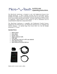
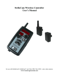
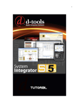
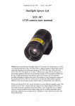
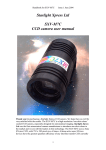
Virtual Astronomical Observation and Development of a
Telescope/Computer Interface
A thesis submitted in partial fulfillment of the requirement
for the Bachelors of Science in Physics from
The College of William & Mary
by David Buchanan Wolcott
Advisor: Dr. Jan Chaloupka
Williamsburg, VA
May 2006
Acknowledgements
Foremost I would like to thank Dr. Jan Chaloupka for the opportunity to work on such a
unique project and for his continual support of my efforts with it.
His patience with my
inexperience as well as the encouragement for me to explore new ideas and methods promoted
education in its most fundamental sense.
I would also like to acknowledge the Information
Technology department at the College of William and Mary for the help they provided with the
technological aspects of this project. Thanks to Dr. John McKnight for his enthusiastic generosity
in allowing the use of his astronomy equipment.
ii
Contents
Acknowledgements ……………………………………………………...
ii
Contents ………………………………………………………………….
iii
Abstract…………………………………………………………………...
1
1. Introduction ……………………………………………………………
2
2. The Equipment and Setup ……………………………………………
3
2.1 The Telescope ……………………………………………...…
3
2.2 The Imaging Package ...............................................................
5
2.3 The Meade LPI Camera...............................................................
5
2.4 The Computer
6
3. Controlling the Telescope .....................................................................
6
3.1 Telescope Calibration ................................................................
7
3.2 Slewing to an Object of Interest ................................................
7
4. Creating an Image .................................................................................
8
4.1 Controlling the Camera ..............................................................
8
4.2 Making a Composite ..................................................................
8
5. The Website ............................................................................................
11
6. Future Applications.................................................................................
12
6.1 Creating a Video Webcam Using the Telescope……………….
12
6.2 Map of the Moon……………………………………………….
12
6.3 Student Use and Database……………………………………...
13
7. Conclusion………………………………………………………………
14
Bibliography……………………………………………………………
15
Image Gallery ……………………………………………………………..
16
Appendix A (User’s Manual) …………………………………………….
18
iii
Abstract
Direct astronomical observation is often limited due to available equipment or time. With
technological advances conventional astronomical observation is becoming obsolete and
computerized systems are gradually becoming the norm, even among amateur astronomers.
This project focused on bridging the technological gap between conventional astronomy and
the more advanced systems that are becoming commonplace. A website was constructed to
store the information gathered by an eyepiece camera mounted onto a 14" Celestron
Schmidt-Cassegrain telescope. It was intended that developing this system could lead to its
use by other students who, after brief instruction, would be able to conduct their own
personal astronomical exploration. The applications of this link pave an exciting path
towards integrating advancing technology with the curiosity about the cosmos inherent in all
of us.
1
1
Introduction
Astronomy is one of the most interesting aspects of the physical sciences in that it has a vast
following of individuals that may or may not be directly involved with science in their professional
lives. One would imagine that it would be somewhat rare to find a mortgage broker who dabbles in
theoretical QCD in her spare time or an elementary school English teacher who studies solid state
NMR spectroscopy in his basement. However, there are many backyard astronomers and sky
watchers as well as magazines and journals dedicated to the amateur observer. There is something
fascinating about what lies beyond our planet and taking a first hand look can be an exhilarating
experience. However, our eyes are not nearly as capable of scientific study as are computers with
the capacity to calculate, recall, analyze, and record.
For this reason, professional astronomical
study almost never entails looking through an eyepiece. Amateur astronomy is now beginning to
adopt some of the same technological advances that have been used by the scientific community.
In this project I aimed to create a platform that would allow individuals without telescopes of their
own to experience the endless possibilities of an observatory. I constructed a systematic method of
operation to be used by approved and instructed physics students to conduct and organize their own
observational experiences in astronomy.
Using the Thomas Harriot Observatory based on the roof of Small Hall I developed a website to
connect the images taken through the telescope with those who would not generally have access to
such equipment.
This project laid the foundation for developing a system of video live-feed of
images captured through the camera and uploaded automatically to the website. I have written a
brief instruction manual (see Appendix A) for linking the camera to the telescope as well as the
most basic instructions for taking photos and storing them online. It is hoped that this could allow
students that are approved by the department to use the system on nights that it is available. By
giving these individuals more freedom to explore the cosmos as they wish, as well as be able to
document their explorations via CCD images, it could further the interest in astronomy and make
the Thomas Harriot Observatory a point of interest for the physics department again.
2
2
The Equipment and Setup
Two of the most important aspects of this project are the equipment and the way in which it is
integrated. Understanding how these two things work is without a doubt the very first step in
understanding this project.
2.1
The Telescope
The primary component of this project was the telescope. In this project two telescopes were used.
The first was a 10" Meade LX200GPS Schmidt-Cassegrain. The second was the 14" Celestron
Schmidt-Cassegrain telescope of the Thomas Harriot Observatory.
The Meade 10" LX200GPS provided motor controlled slewing and focusing. Though it has a
rather large optical tube assembly and is quite heavy, it is still a portable scope and it could be
assembled and disassembled within a matter of minutes. Unfortunately, due to an unforeseeable
problem, this telescope was not used during the latter part of the project.
The 14" Celestron of the T.H.O. added another level of technological sophistication with its
preloaded GPS based guidance and tracking system. Once this telescope was calibrated properly it
could be programmed to pinpoint any object in the night sky and compensate for the rotation of the
earth by automatically using the motors to track the object throughout the night. This provided the
user with the chance to take longer exposures with the camera and thus produce clearer results.
The Schmidt-Cassegrain design of these telescopes is a reflection design that uses two mirror
systems to provide a high precision image. See Figure 1.
3
Figure 1: Schmidt-Cassegrain Design [1]
The light enters the optical tube through the Schmidt corrector plate (labeled as 1) at the front of the
scope. The Schmidt corrector plate is necessary on telescopes with a spherical primary mirror (as
the Schmidt-Cassegrain design does.) It is a lens that compensates for light being reflected at the
edge of the mirror and focuses it at the same point as the light that is reflected from the more
central regions of the primary mirror. [2]
Light from the corrector plate is reflected off the primary mirror located in the back of the tube (2).
This spherical mirror reflects the light to a convex secondary mirror (3) located on the back of the
corrector plate at the front of the scope. This finally reflects the light through a hole in the primary
mirror and directs it to the eyepiece (4).
It should be clear from the diagram that the light travels a much longer path than simply from the
front of the tube to the eyepiece (as is the case for a refracting telescope for example.) In this case
light is making a trip through the tube a total of three times before exiting through the eyepiece.
With this design the telescope has a very long focal length but a relatively short tube. This allows
for a larger aperture and thus more light gathering within a reasonably sized and priced telescope.
4
2.2
The Imaging Package
Meade makes imaging packages that are designed to work with their telescopes. For this project
Meade's Autostar Suite and Lunar Planetary Imager were used.
This imaging package included
some remarkable features such as the ability to track an object using an interface between the
imaging package installed on the computer and the telescope's motor controlled tracking system.
The package also included a catalog of tens of thousands of objects including: 7840 New General
Catalog objects, 5386 Index Catalog objects, 110 Messier objects, 109 objects of the Caldwell
Catalog, and thousands of uncategorized objects. The camera was completely controlled by the
computer and offered a multitude of adjustments that could be made for imaging. A USB cable
connected the camera directly to the computer and all of the controls were manipulated through the
software.[3]
2.3
The Meade LPI Camera
The camera itself is a small CCD (charged coupled device) camera with that boasts a standard
VGA 640x480 resolution. The LPI stands for Lunar Planetary Imager and is best suited for
imaging within the solar system. The camera is simply an eyepiece camera that replaces the
position of a standard eyepiece (See Figure 2.) It connects to the computer via a three foot USB
cable. There are no manual controls for the camera. All commands and adjustments are made
through the computer and the Meade Autostar control package.
Figure 2: The Meade LPI camera. In this photo the LPI has simply taken
the place of a standard eyepiece in the diagonal of this telescope. [4]
5
2.4
The Computer
For this project a Dell Latitude C540 laptop computer was used to control the camera and store the
photos. With wireless networking the operator could research the objects of interest while
observing and taking pictures.
Using additional software or another camera this could provide
video imaging that could be uploaded directly to the internet and viewed remotely.
Since only a three foot cable was provided with the camera, having wireless capabilities as well as
the convenience of a laptop allowed the freedom for the orientation of the workstation in whatever
way seemed necessary for the orientation of the telescope at the time.
3
Controlling the Telescope
Before snapping a photo a few things needed to be done to ensure precision and accuracy. Since
the Earth is obviously rotating, if one were to focus on a particular part of the night sky the objects
within the field of view would appear to be moving in a westerly direction (however slow that may
actually be.) As with any other type of photography, if one wants to take a photo of a moving
object a high-speed film needs to be used. With an instantaneous snapshot the object does not have
the chance to become fuzzy. The downside of this is that by taking an instantaneous snapshot very
little light can be gathered by the camera and thus the object would not be as highly resolved. This
would not pose a problem for a situation where lots of light was available. However, in the case of
astronomical photography very little light is available. Therefore taking an instantaneous snapshot
is not an option. As a matter of fact, deep-sky objects or fainter objects necessitate exposure times
on the order of hours! Due to Earth’s rotation, however, if one focused on a single spot in the sky,
all of the objects of interest would have moved nearly halfway across the visible sky in a time scale
of hours. Telescope makers understand this and have developed telescopes with the ability to track
an object across the night sky and allow for longer exposure times, therefore greater light gathering,
and therefore better photos. The Celestron telescope of the Thomas Harriot Observatory has this
capability but it would only work if the telescope was perfectly aligned and calibrated.
6
3.1
Telescope Calibration
The telescope's GPS based catalog and tracking system holds a substantial amount of information
about the night sky. For all practical observation purposes, to the common sky watcher the stars
that are visible from Earth remain fixed in their positions in relation to other stars. However, since
Earth rotates, the night sky (regardless of how relatively static it is) moves constantly.
The
computerized telescope is advanced enough that it can compensate for this effect by moving at
exactly the same angular speed as Earth's rotation in order to maintain a constant field of view on
an object or area of interest. In order for it to properly do this the user must input the GPS
coordinates of the telescope as well as the date and time (in Greenwich Mean Time). If the
telescope is properly aligned then the user can choose from thousands of stored objects to which the
telescope can automatically slew or simply enter the coordinates of an object of interest.
Aligning the telescope, however tedious, was a relatively simple procedure.
By entering a
command for the telescope to slew to a particular object and centering the object in the field of
view the user could reassign that position of the scope to that object. By repeating this procedure
for a number of reference objects the telescope could be aligned to a high degree of precision.
Alignment could be maintained as long as the user used proper procedures when ending the session
and was careful not to accidentally assign an object to an incorrect scope position.
3.2
Slewing to an Object of Interest
Because of the vast amount of information stored in the telescope's computer guidance system,
most visible objects could be accessed by simply entering a reference number (whether it be New
General Catalog, Index Catalog, Messier objects or Caldwell Catalog.) The telescope in the
Thomas Harriot Observatory also has its own list of about 100 Reference objects that are
commonly sought in the night sky (stars such as Betelgeuse, Sirius, Rigel, Alberio, etc.) If the
scope was aligned then all of these could be accessed by simply punching in a code and the object
of interest would appear in the center of the eyepiece. For taking pictures this features proved to be
extremely useful because the user was not required to remove the camera in order to find the next
object.
7
4
Creating an Image
Obviously, in order to make a meaningful representation of what the telescope sees, one has to
understand a bit about the camera and its software. It is necessary to understand the controls of the
camera as well as how to manipulate and combine photos in order to do with them what is desired.
4.1
Controlling the Camera
The software controls for the LPI camera were very easy to use and applying the appropriate
settings (such as shutter speed, gain, offset, Region-Of-Interest, type of frame, etc.) was simplified
by built in automatic adjustments. If this option was selected the software would analyze the light
entering the CCD for background light, brightness, movement, etc. and adjustments would be made
to the camera accordingly. Once appropriate settings were selected taking a photo was very simple.
The user would press "Start" and the camera would begin taking photos and compiling them
automatically. If different camera settings were desired adjustments could be made manually by
the user.
Each photo as well as the final compilation were saved on the hard drive of the Dell
laptop computer to be accessed and archived later. The option can be selected not to have every
photo saved on the hard drive. However, when the Autostar suite combines them to make the best
final picture it will automatically select the best specimens to overlay. Therefore, it was chosen to
have all individual photos saved on the computer.
It was suggested that 50 was the most efficient number of photos to be taken for the software to
compile a reasonable picture. However, in low light conditions 50 photos might have taken hours
and unless the telescope was perfectly aligned the object could have drifted out of the field of view
during that time. Since the telescope was not used exclusively for this project perfect alignment
was rarely seen and thus taking long exposure photos was generally not an option due to time
constraints.
4.2
Making a Composite
One of the great features of the Meade camera system is that it automatically combines the images
that it takes as it takes them. Whenever the user tells the camera to start taking pictures it
automatically begins to select the best ones and combines them automatically. However, if a
portion of the sky is desired that is broader than the field of view of the camera the photos need to
8
be pieced together by combining images based on common physical features seen in the images to
be combined (See Figure 3.)
Figure 3: Moon Composite 1, Here I combined three photos to make one image
that displays a larger area than a single photo by itself. This type of composite
was used to create the larger composite of the moon shown in Figure 4.
This is an interesting way to present the photos. Using the Microsoft program Paint I was able to
combine images to make composites of the moon, for example (see Figure 3 above.) Essentially I
took the paint program and shrunk the raw photos to a more manageable size and lined up the
identifiable physical characteristics of each photo in order to make an image of a much larger area
of the moon. This was used in the larger moon composite of Figure 4.
9
Figure 4: Moon Composite. This image was created by combining 54 separate photos of the moon and
pieced together using Microsoft Paint. With each photo the common physical characteristics seen in the
individual photos were aligned in such a way that the resulting photo encompassed the entire area
of the moon.
One possible application to this would be to have a full composite of the surface of the moon with
links to the individual photos. The individual photos would not be compressed in size and would
thus provide a more detailed image than the ones used for the composite. This would essentially
provide an option of "Zooming In" to a particular area of the moon. If so desired, one could
research some of the obvious visible physical characteristics of the surface of the moon and perhaps
have detailed photos such as the ones in Figure 3. (For example, the white boxes of Figure 4
represent areas in which a composite was created detailing that section of the moon as in Figure 5.)
10
[5]
Figure 5: Crater Proclus and Details. Using the method of combining photos (as in Figure 3) I created
a detailed composite of one section of the moon. By creating links to established areas of the moon in a large
composite and having the links go to a detailed image such as this one could create a virtual map of the moon
and it could be accessed by “zooming in” (clicking on the link) to find details about that area of the moon.
The only difficulties would arise in the development of the site from which the composite and its
component images would be managed. In order for the main composite to be a reasonable size and
for the detailed images to be detailed, the website portion would be quite complex in terms of the
number of individual pages as well as the network of links that connect them all.
5
The Website
The website was constructed using templates from the College's IT department. These templates
were modified using Macromedia Dreamweaver.
This very powerful program provided the
platform for archiving the images taken as well as constructing a user-friendly site that allowed for
easy navigation. As a program Dreamweaver utilizes HTML coding as well as PHP scripting
within the HTML.
These powerful languages support the creation of very dynamic sites.
11
Understanding and modifying the code proved to be very tedious. However, by working with the
PHP code, a great deal was learned about the structure of a website . With some assistance from
the IT department a reasonable web platform was established and a basic user-friendly site was
constructed. Though the video feed feature has yet to be fully developed the current site contains
many archived photos as well as some detailed composites and a discussion board. Though
currently restricted to those with a William and Mary login and password it is hoped that once the
live feed feature is developed more people will be granted access. The current website can be
found at :
http://dbwolc.people.wm.edu
6
Future Applications
There are a few really interesting things that could possibly be done with this system including a
live-video feed from the telescope’s eyepiece, a virtual “map” of the moon, and a student friendly
platform of usage that would allow students to use the equipment and document their explorations
by saving photos.
6.1
Creating a Video Webcam Using the Telescope
Using the telescope and another type of camera designed for broadcasting, a system could be
established in such a way that a live video image from the telescope’s eyepiece would be uploaded
in real time to a website. Using an approved login one could access this video by simply logging in
to the website. This would provide many people with virtual access to a significantly large
telescope.
6.2
Map of the Moon
Using the methods outlined in section 4 of this paper it would not be a stretch of the imagination to
believe that one could create an online map of the surface of the moon. Depending on the amount
of time at hand, it would be possible to make a very detailed outline of the surface of the moon.
Since it is not possible to zoom with a telescope this effect must be done by shrinking the original
photos and have the user “zoom in” to the originals. Therefore, the number of detailed portions of
the surface would depend on the size reduction of the original photos from the telescope.
12
6.3
Student Use and Database
Perhaps one of the most exciting possible expansions of this project would be to setup a system by
which students (with approval from the physics department as well as instruction) could use the
telescope of the Thomas Harriot Observatory to take photos of their own and store them in an
online database. This would provide incentive for students to pursue knowledge about astronomy
as well as gaining understanding about astrophotography and telescopes. The idea is that students
would be able to go up to the observatory, sign out the camera and computer, and take/save photos
of whatever region of the sky they so desired. The photos would be stored online (as in a website
such as the one I have created) and could thus be available to anyone. [See Appendix A for a
sample instructions manual on how one would operate the camera once he/she was granted access
to the equipment by the department.]
13
7
Conclusion
Ultimately this project proved to be a very educational experience. The knowledge gained about
astronomy, computers, CCD imaging, and telescopes is far more substantial than any single class
could have provided. From the countless hours spent on the roof of Small Hall in the dark to the
hundreds of on-line documents read for this project, it is considered a success regardless of whether
or not the live feed is ultimately achieved. The interface created serves as a platform for further
expansion and the goal of live feed could easily be obtained by simply using additional software or
a different imager. The images collected speak for themselves as far as showing the exciting
possibilities that exist in expanding on the processes described in this paper.
14
Bibliography
[1] - Wikipedia, The Free Encyclopedia, copyright 2005, Schmidt-Cassegrain Telescope, Nov. 39, 2005
<http://en.wikipedia.org/wiki/Schmidt-Cassegrain.html>
[2] - Starizona: Adventures in Astronomy and Nature, copyright 2000-2003, Schmidt Cassegrain Basics, Dec.1, 2005,
<http://www.starizona.com/basics/sct.html>
[3] - Meade Instruments Corporation, copyright 2004, Meade LPI Imager, Dec. 1, 2005,
<http://www.meade.com/autostar/lpi.html>
[4] - Meade Instruments Corporation, copyright 2004,#497 Meade Autostar System, Nov. 30, 2005,
<http://www.meade.com/catalog/autostar/497_autostar.html>
[5] – The Lunar Republic, Full Moon Atlas: Sector C-6, Northern Mare Crisium/ Northeastern Limb, Lunar Republic
Society, April 28, 2006
< http://www.lunarrepublic.com/atlas/sections/c6.shtml >
[6] - Souledout, Phases of Venus, April 12, 2006,
< http://www.souledout.org/nightsky/venusphases/venusphases.html >
15
Image Gallery
Figure 6: Photos of Jupiter. In this set of four photos of Jupiter taken on March 23, 2006 each photo
was taken with different camera settings. Though the camera can automatically adjust the gain, offset, exposure, etc., it
is possible to manually set these parameters. With these photos I was manipulating them to try to get the best overall
image.
16
Figure 7: Saturn. Here I have done the same sorts of adjustments that I did with the photos
of Jupiter.
Figure 8: Phase of Venus on December 9, 2005. Notice that since Venus is an inferior planet it can go through phases
just like the moon. Since it was nearing Earth and between the Earth and the Sun it went through a phase as the moon
does. Even though only about 30% of its surface was illuminated, because of its close proximity it still was at its
highest visual magnitude of the year [6].
17
Appendix A
(Student User Manual)
Basic Instruction for taking photos using the THO and the Meade LPI.
The first step would be to open the observatory, start a session with the telescope computer, and
perform the proper alignment and calibration procedures. This guide assumes that the user will
have been approved by the department and properly instructed on the use of the telescope and the
first step will require no guidance.
This guide also assumes that the MEADE software has been properly installed and tested with the
computer that is to be used.
1. Connect the camera to the computer (before starting the computer):
The first step is to connect the camera to the computer. Before starting the computer
connect the camera to it via the USB cable. Since the cable is only three feet long it is a good idea
to have already established a position within the dome at which you plan to work. One established
turn on the computer and wait for the software to load. This will be indicated by a message that
appears in the lower right hand tool bar of the computer screen. It will indicate “USB Hardware
Found. Meade LPI camera.”
2. Start the Meade Autostar Suite software:
Once the camera has been identified by the computer you can start the Meade
Autostar program. You will be greeted with a screen that will look similar to Figure 9.
Figure 9: Meade Autostar Suite. Once the program is opened the user will be greeted with a screen similar to this one.
What is shown is the night’s sky at that GPS location (which is established when the software is installed) at that time.
By clicking on one of the objects (dots) the Autostar suite will display information about that particular celestial object
(the box in the upper left hand side of the photo.) [3]
18
3. Open the LPI controller
Once the Autostar suite has been opened, navigate to the “Image” button of the toolbar at
the top and select “LPI Imager.” If the camera was connected properly a screen should appear that
looks like Figure 10.
Figure 10: Meade LPI Control Center. It is from this screen that the camera is controlled and manipulations to the
image parameters are made.[3]
From this control center all image parameters are controlled and the camera itself is
controlled exclusively from this screen.
4. Connect the Camera to the Telescope
The camera will simply replace an eyepiece in the eyepiece diagonal of the telescope.
Simply loosen the eyepiece and replace it with the camera. Tighten the thumb screws to secure the
camera. In the case of the T.H.O. orient the camera such that the USB cable hangs down in the
opposite direction of the telescope’s optical tube.
If the telescope is properly aligned, slew to an object of interest and the image should appear in the
screen shown in Figure 10. (Very precise focus is needed in order for the LPI to produce high
quality images. The most effective way of focusing is to have the telescope already in focus for the
LPI through the use of the Parfocal Ring. This is provided with the camera as well as instruction
on how to set the focus. Unfortunately this method requires daytime calibration and I therefore
assume that the scope will either already be properly focused or the student will have been given
proper instruction on how to do this as needed.)
19
5. Start Taking Pictures
When the object of interest is found, focused, and centered in the screen the user can start
taking pictures.
1. Click on the “Auto Adj” button. This tells the computer to do what it thinks is best in terms
of the Exposure, Gain, and Offset.
2. Click on the dropdown menu just below the word “Object” and select the type of object that
is to be photographed. Type in the name of the object in the box “Object Name.” This will
aide in organizing the photos in the database.
3. Click “Start” and the program will automatically start taking photos, compiling them, and
saving them in the specified location (which can be changed in the “settings” menu.) The
amount of time elapsed as well as the number of photos actually taken will be displayed in
the lower left hand corner of the LPI control center screen.
The values for all of the settings of an object within the solar system may look something like this.
Sample:
Exposure: 0.125 sec
Gain: 100
Offset: 50
Track: Off
Combine: Off
Save Every Image: On
Dark sub: Off
Min Quality: 75
Evaluation Count: 20
Mono: Off
Object: Jupiter
Images: 50 taken in 180 sec
File Type: GIF
Keep in mind, THESE SETTING ARE NOT OPTIMUM SETTINGS FOR ALL CASES. THIS IS
JUST AN EXAMPLE.
6. Putting the Photos on the Website
This step would most likely be controlled by a single person. It would be advantageous for
all of those using the camera to save their files in a common directory on the computer so that when
an image gallery is created online (as the one in the website http://dbwolc.people.wm.edu) the
webmaster would not have to search for files from different sessions scatter across the hard drive.
In the case of said website, using an IT template called “Image Gallery” made adding a folder of
photos to the page very easy.
7. Shutting Down
20
Before shutting down the telescope the student must take all the necessary steps of
removing the camera from the scope and shutting down that system before shutting down the scope.
With a camera attached to the eyepiece of the scope, whenever the scope is cycling through its
ending procedures the tube will move. If the camera is still attached when this happens it could
damage the telescope motors, eyepiece diagonal, the camera itself, the computer, etc. ALWAYS
remove the camera and shut down that system before shutting down the telescope.
Ending a session with the camera is very easy.
-Simply remove it from the telescope
-Make sure the program is stopped
-Shut down the Autostar program
-Unplug the camera from the computer
-Replace the black lens cap to the front of the camera
-Replace everything in the case as it was originally
Once again it is assumed that the student will know how to properly end a session with the
telescope and follow proper procedures in shutting it down.
21