1
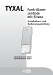
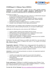
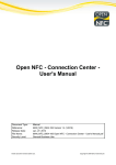
StellaCam Wireless Controller
User’s Manual
For use with StellaCam II, StellaCam3 and Wat-120N, Wat-120N+ astro-video cameras
www.CosmoLogicSystems.com
INSTRUCTION TO THE USER
This equipment has been tested and found to comply with the limits for a class B digital device, pursuant to part 15 of the FCC Rules. These
limits are designed to provide reasonable protection against harmful interference in a residential installation. This equipment generates, uses
and can radiate radio frequency energy and if not installed and used in accordance with the instructions, may cause harmful interference to radio
communications. However, there is no guarantee that interference will not occur in a particular installation. If this equipment does cause
harmful interference to radio or television reception, which can be determined by turning the equipment off and on, the user is encouraged to try
to correct the interference by one or more of the following measures:
•
•
•
•
Reorient or relocate the receiving antenna.
Increase the separation between the equipment and receiver.
Connect the equipment into an outlet on a circuit different from that to which the receiver is connected.
Consult the dealer or an experienced radio/TV technician for help.
In order to maintain compliance with FCC regulations, shielded cables must be used with this equipment. Operation with non-approved
equipment or unshielded cables is likely to result in interference to radio and TV reception. The user is cautioned that changes and
modifications made to the equipment without the approval of manufacturer could void the user's authority to operate this equipment.
The Receiver Unit has been tested to comply with FCC standards. FOR HOME OR OFFICE USE.
Developed and maintained by
CosmoLogic Systems, Inc.
Latest Revision 10-15-10
2
Contents
I. Description ………...………………………………………….……………………………… 4
A. Transmitter Handbox …………………………………………………………...……..… 4
Handbox Features ………………………………….………………………………….. 5
B. Receiver Unit ……………………...……………………………….……...…………….. 7
Installation On The Camera …………………………..……………………………….. 8
II. Operating The StellaCam Wireless Controller ……………………….………….………… 9
Computer Interface ……………………………………………………….……...………….. 9
Control Using StellaCamController.xls (Excel)……………………………...……….… 10
Control Using Batch Files ………………………….......…………………..…………… 12
Control Using HyperTerminal ……………………………………………..…………… 14
III. StellaCam Wireless Controller Commands ………………………………………………… 18
IV. Receiver-Transmitter ID Matching ………………………………………..………………... 18
V. Troubleshooting …………………………………………………………….………………… 19
VI. Specifications …………………………………………..………………….………………….. 20
VII. Warranty Statement ……………………………………………..…………………………… 21
Product Registration Form …………………………………………………………………... 21
3
Thank you for purchasing the StellaCam Wireless Controller for use with your StellaCam II, StellaCam3 or
Wat-120N, Wat-120N+ astronomy video camera. The StellaCam Wireless Controller provides you with
convenient wireless operation of your camera up to distances of 1000 feet. In addition to wireless operation,
the controller also provides an easy to use computer interface allowing you to control your camera from a
personal computer or send control commands from another software application.
For StellaCam3 and Wat-120N+ owners, the controller enhances your camera’s operation by providing
automatic exposure timing far beyond the maximum setting of 8.5 seconds available on the wired handbox.
The wireless controller will now give you automatic exposure timing from 1/2000th of a second up to a full
90 minutes – including a convenient countdown display for exposures greater than one second.
I. Description
The StellaCam Wireless Controller consists of two components: a transmitter handbox unit and a receiver
unit. The receiver unit plugs into the R/C control input of your camera. Power for the receiver is supplied
by the camera through the R/C connector – therefore, the receiver must be connected to the camera
before applying power to the camera. When powered on, the transmitter handbox unit sends commands
to the receiver over a wireless RF data link. The handbox may be turned on either before or after the
receiver/camera is on.
Each transmitter/receiver pair are matched by a unique ID address, however the receiver unit can be
automatically re-programmed to match its ID with any other StellaCam wireless transmitter – see section IV
for a description of this capability.
A. Transmitter Handbox
2
Gain Display
4
Gain Control
& LED Intensity Adjust
6
7
Exposure / Expose Timer
Display
3
Exposure Control
& Timer Display Switch
Iris Control Switch
Gamma Control
Switch
1
St e
Wi
rele
l la
Video Frame Read Display
& Freeze Switch
Ca
ss
Co
ntr
oll
er
m
RS232 Data Port
10
External Power Port
Power On/Off Switch
Handbox Features
4
9
8
5
Handbox Features:
(1) Exposure / Expose Timer Display:
Displays exposure time in minutes and seconds.
Displays exposure countdown timer when selected by Timer Display Switch.
(2) Gain Display:
Displays video amp gain as a percentage of full gain.
(3) Exposure Control & Timer Display Switch:
Controls exposure time when rotated.
Toggles display between “exposure time” and “exposure countdown timer” when pressed
(4) Gain Control & LED Intensity Adjust:
Controls gain of video amp when rotated.
Controls intensity of LED displays when rotated while being pressed down.
(5) Video Frame Read Display & Freeze Switch:
Flashes green when a video frame update occurs.
Turns red and freezes the current video frame when pressed. Unfreezes and starts a new exposure when
pressed again.
(6) Iris Control Switch:
Enables or disables camera control over the iris of an external lens.
(7) Gamma Control Switch:
Switches gamma correction between Off, Low and High.
(8) RS232 Data Port:
Provides connectivity to a host computer using the supplied RS232 interface cable.
(9) Power On/Off Switch:
Turns power on or off when pressed.
(10) External Power Port:
Provides operation by using an external power adapter ranging from 6vdc up to 35vdc.
Uses standard 2.1mm power connector with center positive polarity.
Disables the battery saving timeout when external power is connected.
The transmitter handbox can operate up to 200 hours on 2-AA standard alkaline batteries (depending on
LED intensity setting) or indefinitely from its external power input. You can also use 1.5v lithium AA
batteries for much longer operation. Power is applied by pressing the POWER On/Off button. When
operating on batteries and the power is left on, a “battery saving” timeout feature will automatically turn the
handbox off if no settings are changed within a certain timeout period. The timeout period is factory set to
30 minutes, however the user can change it from 1 minute up to 2 hours, or disable the timeout such that it
will not automatically turn off. While external power is connected, the timeout feature is automatically
disabled. Battery saving timeout control is accessed over the serial RS232 data link (see Computer Interface
section).
5
A “Batt Lo” indication is momentarily displayed at regular intervals when the battery voltage drops down to
2.7v or less. The handbox will operate for several hours following a “Lo Batt” warning, however it is
recommended that either external power be applied or that the batteries be replaced when possible.
The handbox supports two different modes of operation: StellaCam II mode and StellaCam3 mode. The
default is StellaCam3 mode. The operating mode is displayed on the LED readout immediately after power
is turned on. The StellaCam II mode is indicated by “SC-2” and the StellaCam3 mode is indicated by “SC3”. The two modes of operation are identical except for the exposure times that are supported. In the “SC2” mode, only the StellaCam II exposure times of .017sec to 8.533sec are allowed. In the “SC-3” mode,
exposure times ranging from .0005 seconds to 90 minutes are allowed. It should be noted that either
operating mode will control all of the supported cameras, however only the exposure times appropriate to
the camera being used will actually be implemented. The operating mode can be changed by accessing it
over the serial RS232 data link (see Computer Interface section).
All handbox settings are stored in non-volatile memory so when you turn the power on, the settings will be
the same as they were the last time it was used – including the LED intensity setting.
The handbox contains rotary knobs and switches allowing the operator to control the following camera
parameters:
•
•
•
•
•
Exposure Time
Gain
Freeze Frame
Iris Control
Gamma Setting
Exposure Time
Exposure times are displayed on a 4-digit LED readout. The exposure times are “dialed in” by turning a
rotary knob to the desired setting. Exposure times ranging between 1 second and 5 minutes are selected
with a 1-second resolution. Exposure times from 5 to 90 minutes are selected with a 1-minute resolution.
The rotary knob used for setting the exposure time also doubles as a push button switch for displaying an
exposure countdown timer. When pressed, the LED readout toggles between displaying the exposure time
and displaying the exposure countdown timer. If the rotary knob is turned while the countdown timer is
being displayed, then the new exposure time is momentarily displayed – exposure countdown resumes after
the new selection is made.
When exposure times are changed, the current exposure is adjusted to satisfy the new setting. For example,
suppose the exposure time was set to 40 seconds but changed to 50 seconds. If the current exposure had
been running for 20 seconds, then it will now continue for an additional 30 seconds to give you a 50-second
exposure. Now suppose the 40-second exposure setting was changed to 30 seconds. If the current exposure
had been running for 20 seconds, then it will now continue for only 10 more seconds to give you a 30second exposure.
Gain
The camera’s gain is displayed on a 2-digit LED readout. The gain settings are “dialed in” by turning a
rotary knob to the desired setting. The gain setting ranges from 00 to 99 corresponding to the camera’s
video amplifier gain of 8dB to 38dB. Therefore the gain resolution is 0.3dB per step change. The gain
setting can be interpreted as a percentage of the camera’s gain range - going from 0% (8dB) to 99% (38dB).
6
The gain rotary knob also doubles as an LED intensity adjustment. When pressed down while rotating, the
intensity of the LED displays (including the Freeze/Read LED) is adjusted. Turning the knob clockwise
increases LED brightness, turning it counter-clockwise decreases LED brightness.
Freeze Frame
When the exposure has finished (countdown goes to zero) the “READ” LED will flash green indicating that
the camera video frame has been updated with a new image. The READ LED doubles as a Freeze Frame
control switch. When pressed, the LED turns red indicating that the camera’s video image has been
“frozen” indefinitely. When pressed again, the red LED turns off and a new exposure begins.
Iris Control
The Iris Control switch enables or disables camera control over the iris of an external lens. When a lens
with auto-iris capability is connected to the auto-iris control port of the camera, the control feature of the
camera can be enabled or disabled. With the Iris Control switched to the “OPEN” position, the camera
control is disabled forcing the lens iris to be fully open. With the Iris Control switched to the “CTRL”
position, the camera will have auto control over the lens iris, adjusting the iris opening based on the
intensity of light.
Gamma Setting
Gamma correction is used to compensate for the non-linear voltage/intensity response of a monitor
displaying an image from the camera. Gamma correction basically controls the overall brightness of the
image.
The Gamma Setting switch allows you to choose three different levels of gamma correction to the video
image. Setting the switch to the OFF position disables gamma correction (gamma = 1.0). Setting the switch
to LO applies a gamma correction of 0.45 to the video image (increased intensity). Setting the switch to HI
applies a gamma correction of 0.35 to the video image (highest intensity).
B. Receiver Unit
The receiver unit performs all of the camera control operations. It comes standard with an external 1.25”
whip antenna, but is optionally available with an internal planar antenna. The internal antenna version has
about 12% less range than the external version, but may come in handy for applications where space is
limited or a small cross-sectional area is desired (i.e. reducing aperture blockage with HyperStar mounting).
The receiver unit receives commands from the transmitter handbox over a wireless RF data link. All of the
camera control parameters are saved in non-volatile memory so that when you turn the power on, the
settings will be the same as they were the last time it was used. If the handbox is turned off or automatically
shuts down, the receiver will continue to control the camera based on the last settings it received from the
transmitter.
The receiver automatically detects which type of camera it is connected to and controls it based on the
commands received by the transmitter along with the camera’s capabilities. Upon power up, the receiver’s
LED will flash three times if it is connected to either a StellaCam3 or Wat-120N+. The LED will flash
twice if it is connected to either a StellaCam II or Wat-120N. This indicator tells the operator that the
receiver has correctly detected the camera type and is functioning properly. If the receiver’s LED does not
exhibit this when power is applied, then either the camera’s power plug should to be pulled out and reconnected or the camera’s power source should be turned off and then back on.
7
Installation On The Camera
The receiver unit is installed on the camera by plugging it into the R/C port of the camera. This must be
done before applying power to the camera. Installation is accomplished by orienting the receiver with
respect to the camera as shown in the diagram below and then gently inserting the connector ring into the
mating circular slot on the camera. Rotate the receiver slightly while applying a small amount of pressure
until you feel the connector pins engage properly in their respective sockets. The receiver should be aligned
vertically with the camera body. Once you achieve proper alignment of the pins, apply additional pressure
until the connector ring is completely seated into the camera.
The receiver unit is very light and small, therefore it may be desirable to just leave it in the camera while the
camera is being stored and not in use. This would reduce the set-up time plus eliminate wear on the
connector components.
Connector Ring
Receiver Installation
8
II. Operating the StellaCam Wireless Controller
The StellaCam Wireless Controller was designed to be as simple to use as possible. Simply plug the
receiver unit into the R/C connector of your camera, power up the camera, and turn the transmitter handbox
power on. You may now control your camera using the handbox up to 1000 feet away.
Several of the StellaCam Wireless Controllers may be operated within range of each other (at star parties)
without concern for interference. They have been designed with unique ID addresses and data timing
characteristics that prevent them from interfering with one another.
Computer Interface
The transmitter handbox may be operated remotely from a personal computer by using its serial RS232 data
link. This feature gives you the ability to control your camera from a host computer. A serial interface
cable is supplied with your wireless controller system that connects the handbox to the com port on your
computer. The interface cable uses standard RJ11 phone line, therefore it can easily be extended in length if
desired. If your computer does not have a COM port, then a Serial-to-USB adapter may be connected to the
cable in order to connect to one of your computer’s USB ports.
Ste
Wi
rele
l la
RS232 Interface Cable
(standard phone line with 9-pin adapter)
Ca
ss C
ontr
oll
m
er
Connect To Computer's
9-pin COM Port
OR
Serial-to-USB Adapter
Computer Interface Cable Connection
9
To control the handbox from your computer, you can either send “text” commands from a batch (.bat) file
or run a communications program such as Procomm or HyperTerminal. An Excel file,
“StellaCamController.xls”, is also provided which allows the user to easily control the camera based on
preset parameters that the user can specify for over 180 different objects. You can also write your own
application software to send the supported “text” commands.
Control Using StellaCamController.xls
For users who have Microsoft Excel (2003 or later) installed on their PC, the StellaCam Wireless Controller
can be controlled from your computer by using the file “StellaCamController.xls”. This file is provided on
the CD that came with your controller. It can also be downloaded from the StellaCam Yahoo User Group
(http://tech.groups.yahoo.com/group/stellacam/) in the “Files” section. This file allows the user to specify
the Exposure Time, Gain Setting and Gamma Setting for over 180 objects in a spreadsheet list. The data
can then be output to the camera by simply clicking a button.
The program uses macros, so when started you may see the following screen:
Click the “Enable Macros” button to allow the program to run.
10
The following screen will now appear:
The spreadsheet contains some sample object data that can be changed by the user. To use the program, just
enter an Object Name, Site/Condition information, Exposure Time, Gain and Gamma setting for an object,
then click the “Output Data to Camera” button for that object. Optionally you can enter an Order# which is
used for sorting the data. There are two “sort” buttons available allowing the object list to be sorted by
either Object Name or Order#. There is also a COM port “pull down” list allowing the user to select which
RS232 COM port is to be used to output the data through.
The Exposure Time is specified in seconds and can range from .0005 seconds to 5400 seconds (90 minutes).
For sub-second exposures, it will output the nearest time value supported by the camera. The Gain values
can range from 00 to 99. The Gamma values can be 0, 1 or 2 which specify Off, Low or High for the
gamma setting.
When an “Output Data to Camera” button is pressed, a macro is executed that outputs the camera control
parameters to the Handbox via the selected COM port by using embedded batch file commands (reference
Control Using Batch Files). The object’s row is then highlighted to indicate which data was the last to be
sent.
11
Control Using Batch Files
The StellaCam Wireless Controller can be controlled from your computer by using batch files to send
commands to the handbox. You can create simple batch files that can be “double-clicked” to send
commands directly to the handbox. A batch file consists of text commands that are executed when you
double-click the file’s icon. A text editor such as Microsoft Notepad can be used to create a batch file.
Below is an example of a batch file called “Set to SC2 Mode .bat”, which changes the operating mode of the
wireless controller to “StellaCam II” :
Example File: “Set to SC2 Mode .bat”
MODE COM1: BAUD=4800 PARITY=N DATA=8 STOP=1 TO=ON XON=ON OCTS=OFF ODSR=OFF IDSR=OFF DTR=ON RTS=ON
PRINT "SC2" > \\.\COM1
The first line in this file initializes the com port (COM1 in this case) with the proper settings for
communication with the handbox. Once the com port is initialized, data can be sent via PRINT commands.
In this case, the text command “SC2” is sent out the serial COM1 port to the handbox. The com port only
needs to be initialized once, however it’s usually a good idea to include the initialization command at the
beginning of each batch file just to make sure the com port gets set up properly. (Note: the \\.\ characters
preceding COM# allows com port numbers greater that 9 to be used)
Suppose you wanted to turn off the “battery saving feature” such that the controller does not automatically
shut itself off after a timeout period.* The example batch file below would accomplish this by changing
the timeout period to 121.
Example File: “Turn Battery Savings Off .bat”
MODE COM1: BAUD=4800 PARITY=N DATA=8 STOP=1 TO=ON XON=ON OCTS=OFF ODSR=OFF IDSR=OFF DTR=ON RTS=ON
PRINT "BTO121" > \\.\COM1
Perhaps you would like to change the timeout period to be one hour. The batch file below accomplishes this
by commanding the battery saving timeout period to be 60 minutes.
Example File: “Set Battery Saving Time-out To 60min .bat”
MODE COM1: BAUD=4800 PARITY=N DATA=8 STOP=1 TO=ON XON=ON OCTS=OFF ODSR=OFF IDSR=OFF DTR=ON RTS=ON
PRINT "BTO060" > \\.\COM1
Several controller commands can also be sent at the same time within a single batch file. This feature
allows you to easily configure your camera with “pre-stored” settings for various stellar objects that you
may be interested in viewing. For example, you could have a folder containing optimal camera settings for
“DSO objects” that you had previously determined. To configure the camera for a particular object, you
would just connect the data cable between your computer and the handbox, then double-click on the
“setting” file for that object. The camera (and handbox) will then be configured with your desired settings.
After this, you can disconnect the data cable and the settings will be maintained indefinitely until you decide
to change them again.
* NOTE: The battery saving feature is temporarily disabled whenever external power is connected to the handbox.
12
Comment lines may also be added to a batch file, however they must be preceded by the text “rem”
(remark). Below is an example of a typical batch command file called “M51 Camera Settings .bat”, which
sends a set of commands to the handbox that may configure the camera for optimal viewing of M51:
Example File: “M51 Camera Settings .bat”
Echo off
Rem - Optimal Settings for SC3 camera to view M51 (Whirlpool Galaxy) with 12" LX200GPS scope at f/3.3 located in my back yard
MODE COM1: BAUD=4800 PARITY=N DATA=8 STOP=1 TO=ON XON=ON OCTS=OFF ODSR=OFF IDSR=OFF DTR=ON RTS=ON
Rem PRINT
Set Exposure To 45sec
“ XPS045”
Gain=73%
“GN73”
Gamma=LO
Iris = OPEN
“GAM1”
“IRS0”
Un-Freeze The Display
“FRZ0”
> \\.\COM1
The “Echo off” batch file command inhibits the text in the file from being sent to the screen during
execution. When sending multiple commands using a batch file, all of the text commands may be on the
same line following the PRINT command. Each text command must by enclosed by quotes and there must
be at least one space between them. The end of the line must have the “> \\.\COMn” (where n = 1-99)
designator to specify which com port is being used.
The following “sample” batch file commands are provided on the CD that came with your controller:
Expose 1min Gain-57 Gama-OFF Iris-OPEN Unfreeze.bat
Expose 15s Gain-43 Gamma-LO Iris- OPEN Unfreeze.bat
Freeze.bat
M51 Camera Settings .bat
Set Batt Saving Timeout to 1min.bat
Set Batt Saving Timeout to 30min.bat
Set to SC2 Mode.bat
Set to SC3 Mode.bat
Turn Off Batt Saving Timeout.bat
UnFreeze.bat
Simply connect your handbox to COM1 of your PC and double-click on one of these files to send the
command (to use a different com port, you will need to edit the file). These sample batch files can also be
downloaded from the “Files” section of the StellaCam Yahoo User Group at
http://tech.groups.yahoo.com/group/stellacam/.
A list containing all of the supported text commands can be found in section III of this manual. This list can
also be displayed when using HyperTerminal by selecting the “Display PC Commands” item in the
parameter menu list, then press the Right or Left arrow key (refer to the “Control Using HyperTerminal”
section).
13
Control Using HyperTerminal
HyperTerminal is a standard communications accessory that comes with all Windows operating systems.
With HyperTerminal running, you will get a display showing all of the wireless controller parameters along
with instructions on how to modify them.
To invoke HyperTerminal*, click “Start” (lower left of your computer screen), then go through the
following menus:
Programs > Accessories > Communications > HyperTerminal
When HyperTerminal is invoked, the following screen will appear:
* If HyperTerminal is not on your system, then you will need to insert your Windows CD and install it.
14
Type in a connection name (such as “ Wireless Controller”) and click OK.
Now the following “Connect To” screen appears:
Click on the “Connect using” pull-down menu and select a com port. If you are connected to your
computer’s com port then choose COM1. If you are using a Serial-to-USB adapter, then choose the com
port number assigned to your adapter.* Click OK.
Now the following “COM Properties” screen appears:
Change the “Bits per second” to 4800. Set the other parameters to: Data bits = 8, Parity = None,
Stop Bits = 1, Flow Control = None or XON/XOFF
Click OK.
* To identify your adapter’s com port assignment, look in the Device Manager under “ports” (Control Panel>System>Hardware>Device
Manager). It will show your adapter with the assigned com port in parenthesis.
15
You will now have the HyperTerminal screen running as shown:
At the lower left of the screen, a clock should be running showing the elapsed time since the connection was
started.
Connect the interface cable from the handbox to your computer and the message “Press ENTER Key To
Connect” should be displayed on the screen. Press ENTER and a display similar to the one below will
appear:
You can select a parameter by pressing the Up/Down arrow keys, then change its value by pressing the
Left/Right arrow keys.
16
Parameters can also be changed by sending commands located in text files by using the HyperTerminal
“Transfer” menu operation. For example, suppose you would like to save the optimum settings for viewing
certain stellar objects in a folder. You would like to be able to just select a file that sets up the camera for
optimal viewing of your favorite DSO. This can easily be done by creating text files that specify the desired
settings you would like for each object. Text files can be created with a text editor such as Windows
Notepad and stored in a folder. They can then be “executed” by using the HyperTerminal “Transfer”
operation. In HyperTerminal you would click on “Transfer”, then select “Send Text File…”. This
operation opens a popup window allowing you to select a command file from your designated folder.
Double-clicking on your command file (or clicking on “Open”) causes the commands to be sent to the
handbox. The new settings are then displayed on both the handbox and the HyperTerminal screen.
Below is an example of a typical text command file called “M51 Camera Settings .txt”, which may
configure the camera for optimal viewing of the Whirlpool Galaxy.
Example File: “M51 Camera Settings .txt”
Optimal Settings for SC3 camera to view M51 (Whirlpool Galaxy) with 12" LX200GPS scope at f/3.3 located in my back yard
Set Exposure Time To 45 Seconds:
XPS045
Set Gain To 73%:
GN73
Set Gamma To LOW:
GAM1
Set Iris Control To OPEN:
IRS0
Un-Freeze The Display (if it was currently frozen):
FRZ0
This file consists of comment lines and command lines. Each command in this file is located directly under
the comment describing it. The comment lines are optional and are only used for descriptive purposes. The
command lines are required and each command must be on a separate line. A list of supported text
commands can be displayed by selecting the “Display PC Commands” item in the parameter menu list, then
press the Right or Left arrow key. The list can also be found in section III of this manual.
When exiting HyperTerminal, it will ask you if you want to save the connection. If you select YES, a
HyperTerminal setup file (Wireless Controller.ht) will be created. The file will be located in the
HyperTerminal Folder (Programs > Accessories > Communications > HyperTerminal [folder]). So the next
time you want to control the handbox using HyperTerminal, just click on the “Wireless Controller.ht” icon.
For convenience, you may want to create a link to “Wireless Controller.ht” and save it to your Windows
desktop or some other appropriate folder.
17
III. StellaCam Wireless Controller Commands
The following is a list of text commands that are supported by the StellaCam Wireless Controller’s RS232
computer interface:
COMMAND
DESCRIPTION
SC2<cr>
SC3<cr>
GNxx<cr>
GAMx<cr>
IRSx<cr>
FRZx<cr>
BTOxxx<cr>
XPMNxx<cr>
XPSxxx<cr>
XPSSxx<cr>
Set To StellaCam 2 Mode
Set To StellaCam 3 Mode
Set Gain
Set Gamma
Set Iris
Set Freeze
Change Batt Saving Time-Out
Set Exposure Time in Minutes
Set Exposure Time in Seconds
Set Exposure Time in Sub-Seconds
S#<cr>
Display Serial Number ID Code
NUMERIC
RANGE
00 to 99
0, 1 or 2
0 or 1
0 or 1
001 to 121
01 to 90
001 to 299
00 to 04
05 to 10
UNITS
Percentage (0%-99%)
Off, Low or High
Open or Control
Run or Freeze
Minutes (121 = Always On)
Minutes
Seconds
= .0005 .001 .002 .004 .008sec (SC3 Only)
= .017 .033 .067 .133 .267 .533sec
Notes:
• All of the text command characters must be “upper case”.
• “x” represents a numeric value between 0 and 9.
• <cr> represents a Carriage Return (inserted in a text file by pressing the Enter key) .
- Carriage Returns are not needed when commands are used in batch files and enclosed by quotes.
IV. Receiver-Transmitter ID Matching
Each StellaCam Wireless Controller transmitter unit is “hard programmed” with a unique ID address, which
is transmitted whenever data is sent to the receiver. The receiver unit has been pre-programmed with the
same ID address to match its corresponding transmitter, however it is capable of automatically reprogramming itself to match its ID with any other StellaCam wireless transmitter. This unique feature
provides the user with flexibility for applications where multiple wireless systems may be used. For
example, a single handbox could be used to control several different cameras simultaneously.
Automatic programming of the receiver’s ID can be accomplished by pressing a yellow pushbutton switch
located on the internal circuit board – just to the right of the antenna. In order to do this, you must remove
the enclosure cover of the receiver unit and install the receiver back in the camera with the circuit board
exposed. Apply power to the camera and press the yellow pushbutton switch. The receiver’s LED will
blink three times to indicate that it is now ready to receive an ID signal from the transmitter. Next, turn the
handbox power on and you will see the receiver’s LED flash about eight times – it is now pre-programmed
to match up with that handbox. Change some settings on the handbox and the receiver’s LED will flash to
indicate that it is receiving signals from the handbox transmitter. Turn the camera/receiver power off,
remove the receiver, replace its enclosure cover, and re-insert it back in the camera. You can now control
the camera with the handbox via the newly programmed receiver.
18
V. Troubleshooting
The StellaCam Wireless Controller utilizes Microprocessor based Control Units (MCUs) to provide all of
the display and control functions. The handbox MCU generally operates fine even with very low battery
conditions, however a momentary glitch on the voltage to the MCU can cause the processor to “hang up”.
If this were to occur, the LED displays may freeze or go blank and the controls would become nonresponsive. This situation can easily be corrected by resetting the MCU. To reset the MCU simply remove
one of the AA batteries, then reinstall it (make sure that external power is not connected before doing this).
If the batteries in the handbox are getting low, a “Batt Lo” warning message will momentarily appear on the
LEDs. This low battery condition may cause voltage glitches to occur when turning the power on or off. It
may also cause a glitch to occur when disconnecting the external power while the handbox is on. If the
batteries are low, it is recommended that they either be replaced with new batteries or that the handbox be
connected to an external power source.
Even if the handbox were to “freeze up”, this would not affect the exposure timing, gain, or any other
camera parameter. These parameters are controlled by the receiver unit and are independent of the handbox
when no transmissions are being received from the handbox. The receiver unit is powered by the camera’s
regulated 5-volt supply and is therefore not prone to problems caused by low battery voltages.
On rare occasions, the receiver may experience problems at power-up. When plugging a power connector
into the camera, transients on the supply voltage may affect the receiver’s “power-on reset” circuit causing
the receiver’s processor to “hang up”. When power is applied, the receiver’s LED should flash either 2 or 3
times depending on which camera it is connected to. This indicator tells the operator that the receiver has
correctly detected the camera type and is functioning properly. If the receiver’s LED does not exhibit this
when power is applied, then either the camera’s power plug should be pulled out and re-connected or the
camera’s power source should be turned off and then back on.
19
VI. Specifications
Operating Temperature Range:
-35 °C to 70 °C (-31 °F to +158 °F)
Transmitter/Receiver Operating Range:
Up to 1000 feet (depending on obstacles)
Receiver Power Input:
5 volts, 14mA (from camera)
Handbox Internal Power Input:
3 volts, 5mA-to-16mA max (2 AA Batteries)
Handbox External Power Input:
6-to-35 volts DC at 50mA or greater
Connector: 2.1mm with center positive polarity
Battery Life:
Approximately 200 hours of operation (depending on
LED intensity or type of battery)
Battery Saving Timeout:
User Programmable (1-120 minutes or Always On)
Low Battery Warning Threshold:
2.70 volts (for 2 batteries)
Auto Exposure Range – StellaCam II Mode:
0.017sec to 8.533 sec
Auto Exposure Range – StellaCam3 Mode:
0.0005sec to 90min
Gain Settings:
00 to 99 (8dB to 38db)
Gain Resolution:
0.3dB
Serial RS232 Com Port Parameters:
Connector:
Baud Rate:
Data Bits:
Parity:
Stop Bits:
Flow Control:
Terminal Emulation:
RJ-11 phone jack with 9-pin female D-Sub adapter
4800 bits per second
8 bits
None
1, 1.5 or 2
None or Xon/Xoff
TTY or Auto Detect
Transmitter Handbox Weight:
6 ounces
Receiver Weight:
1 ounce
Transmitter Handbox Dimensions:
Approximately 5”H x 2.8”W x 1”D
Receiver Dimensions:
3.2”H x 1.3”W x 0.6”D (external antenna version)
1.9”H x 1.3”W x 0.75”D (internal antenna version)
(Note: Range is decreased about 12% with internal antenna version)
20
VII. Warranty Statement
The manufacturer warrants the original purchaser of the STELLACAM WIRELESS CONTROLLER
(SWC) that it shall be free of defects resulting from faulty manufacturer of the product or its components for
a period of one year from the date of sale. Defects covered by this warranty shall, at the option of the
manufacturer, be corrected either by repair or by replacement. The replaced components will be warranted
for the remainder of the original one year period.
The sole obligation of the manufacturer under this warranty is limited to repair or replacement of products
pertaining to the SWC only, which prove to be defective within one year of purchase. The manufacturer
shall not, in any event, be liable for any consequential damages or loss of profits of any kind resulting from
the use of the SWC or the technical information enclosed in this document.
Please fill out the Product Registration Form and fax or mail it to CosmoLogic Systems, Inc. This product
must be registered within thirty (30) days from the date of purchase in order to activate your warranty
coverage.
____________________________________________________________________________________
Product Registration Form
Please fill out the following information and send it to:
CosmoLogic Systems, Inc.
11112 204th Ave Ct. East
Bonney Lake, WA 98391
Ph: (253) 862-4863
Fax: (253) 863-1689
Email: [email protected]
www.CosmoLogicSystems.com
By sending this form back to us, we can let you know of additional products and upgrades as they become available. This form is
also used to activate your warranty coverage.
Name
Address
Phone
City
Camera Type
State
StellaCam Wireless Controller Serial Number
Email
Purchased From
Zip
Date Purchased
21