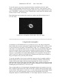
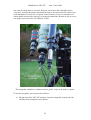
1
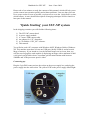
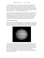
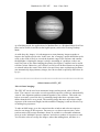
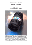
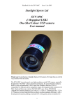
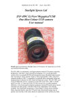
Handbook for SXV-M7
Issue 1 June 2004
Starlight Xpress Ltd
SXV-M7
CCD camera user manual
Thank you for purchasing a Starlight Xpress CCD camera. We hope that you will be
very satisfied with the results. The SXV-M7 is a high-resolution cooled CCD camera,
especially designed for astronomical imaging. The SXV-M7 uses a Sony EXview
CCD, with 752 x 582 pixels in a 6.5mm x 4.8mm active area. EXview devices have
the greatest quantum efficiency of any interline transfer CCD currently available and
the use of high performance microlenses on the CCD surface gives the greatest
possible throughput of light to the pixels. This camera is a next generation version of
the parallel port driven MX716, but the use of an internal USB2 interface and the
addition of an external guide camera option makes it considerably more effective.
Please note that the SXV-M7 can be operated in several different imaging modes. The
easiest to use is ‘Fast’, which creates an image from a single exposure and so this is
the mode used in the operating instructions below. ‘Fast’ mode does give a slightly
reduced vertical resolution in the output image, but this is barely detectable unless
observing conditions are extremely good. ‘Progressive’ and ‘Interlaced’ modes will
be described later.
1
Handbook for SXV-M7
Issue 1 June 2004
Please take a few minutes to study the contents of this manual, which will help you to
get the camera into operation quickly and without problems. I am sure that you want
to see some results as soon as possible, so please move on to the ‘Quick Start’ section,
which follows. A more detailed description of imaging techniques will be found in a
later part of this manual.
‘Quick Starting’ your SXV-M7 system
In the shipping container you will find the following items:
1)
2)
3)
4)
5)
6)
The SXV-M7 camera head.
A power supply module.
A 3 metre USB camera cable.
An adaptor for 1.25” drawtubes.
A CD with the ‘SXV_M7’ software.
This manual.
You will also need a PC computer with Windows 98SE, Windows 2000 or Windows
XP. This machine must have at least one USB port (ideally USB2.0) and at least 64
Megs of memory. If you intend to view the finished images on its screen, then you
will also need a graphics card capable of displaying an image with a minimum of 800
x 600 pixels and 65,000 colours. A medium specification Pentium with between
500MHz and 3GHz processor speed is ideal.
Connecting up:
Plug the 5 pin DIN connector into the socket on the power supply box, and plug the
power supply into the wall socket. The yellow LED on the power supply should light.
2
Handbook for SXV-M7
Issue 1 June 2004
Connect the miniature 4 way power plug to the socket on the rear of the camera and
screw the retaining ring into place. The LED on the rear of the camera will light a dim
yellow. The other connections should not be attached until after the software has been
installed.
Installing the software:
Switch on the computer and allow it to ‘boot up’. Once you have the system ready to
run, insert the program disk into your CD drive and select ‘Setup.exe’ if the disk does
not autostart. The initial installation is to set up the USB drivers required by the SXV
electronics. The files SXVIO.sys and Generic.sys are copied to your
Windows\System32\Drivers folder and SXV_M7.inf is copied to Windows\Inf.
After this, the program ‘SXV_M7.exe’ will be installed into your ‘CCD’ directory
and a new directory called ‘Autosave’ will now exist on the same drive. ‘Autosave’ is
where SXV_M7 will normally store its configuration file, ‘SXVM7.ini’, and any
image files, which are recorded using the ‘Autosave’ mode in SXV_M7 and saved in
FITs format.
3
Handbook for SXV-M7
Issue 1 June 2004
You now need to set up the camera control defaults (shown above), as follows:
Start SXV-M7 by clicking on the icon and select the ‘File’ menu. Now select ‘Set
program defaults’ and a window, which contains the various software settings, will
appear. Suggested starting defaults are as follows:
1)
2)
3)
4)
Background Image area
Red (or as preferred)
Interlaced image smoothing
On
FITS Unsigned Integer format
Off
Star mask size (area used for photometry and guiding)
8 pixels
The other default settings are not important for current purposes and may be left as
the software start-up values for now.
Recording your first image:
We now have the camera and computer set up to take pictures, but an optical system
is needed to project an image onto the CCD surface. You could use your telescope,
but this introduces additional complications, which are best avoided at this early
stage. There are two simple options, one of which is available to everyone:
1) Attach a standard ‘M42’ SLR camera lens to the SXV-M7, using a 27mm spacer
to achieve the correct focal distance. M42 thread spacers are available from most
photographic stores, or from Starlight Xpress dealers.
4
Handbook for SXV-M7
Issue 1 June 2004
2) Create a ‘Pin hole’ lens by sticking a sheet of aluminium baking foil over the end
of the 1.25” adaptor and pricking its centre with a small pin.
If you use a normal lens, then stop it down to the smallest aperture number possible
(usually F22) as this will minimise focus problems and keep the light level reasonable
for daytime testing. The pin hole needs no such adjustments and will work
immediately, although somewhat fuzzily.
5
Handbook for SXV-M7
Issue 1 June 2004
Point the camera + lens or pinhole towards a well-lit and clearly defined object some
distance away. Now click on the camera icon in the toolbar of the SXV-M7 software
and the camera control panel will appear (see above). Select an exposure time of 0.1
seconds and press ‘Take photo’. After the exposure and download have completed
(between 1 and 3 seconds) an image of some kind will appear on the computer
monitor. It will probably be poorly focused and incorrectly exposed, but any sort of
image is better than none! In the case of the pinhole, all that you can experiment with
is the exposure time, but a camera lens can be adjusted for good focus and so you
might want to try this to judge the image quality that it is possible to achieve.
One potential problem with taking daylight images is the strong infrared response of
the SXV-M7 and this will cause ‘soft focus’ with camera lenses. Soft focus with
camera lenses is much reduced by keeping the aperture setting below F8. IR blocking
filters are available from various suppliers (True Technology, Edmunds etc.) and are
recommended for the best results.
If you cannot record any kind of image, please check the following points:
1) Is the power LED on?
2) Does the software indicate that the camera is successfully connected? An attempt
to take a picture will fail with an error message if the USB is not properly installed. In
this case, try unplugging the USB cable and then reconnecting it after about 5
6
Handbook for SXV-M7
Issue 1 June 2004
seconds. Restart the camera software and see if it can link now. If not, check in
Windows device manager (via ‘System’ in ‘Control Panel’) and see if the BlockIO
device is installed properly.
3) If you cannot find any way of making the camera work, please try using it with
another computer. This will confirm that the camera is OK, or otherwise, and you can
then decide how to proceed. Also check on our web site to see if there are any updates
or information about your camera software that might help. The message board might
prove useful to ask for help with getting your camera operating properly.
Our guarantee ensures that any electrical faults are corrected quickly and at no cost
to the customer.
Enhancing your image:
Your first image may now be reasonably good, but it is unlikely to be as clear and
sharp as it could be. Improved focusing and exposure selection may correct these
shortcomings, and you may like to try them before applying any image enhancement
with the software. However, there will come a point when you say, “That’s the best
that I can get” and you will want to experiment with various filters and contrast
operations. In the case of daylight images, the processing options are many, but there
are few that will improve the picture in a useful way.
The most useful of these are the ‘Normal Contrast Stretch’ and the ‘High Pass Low
Power’ filter. The high pass filter gives a moderate improvement in the image
sharpness, and the effects of image processing. This can be very effective on daylight
images. Too much high pass filtering results in dark borders around well-defined
features and will increase the ‘noise’ in an image to unacceptable levels, but the ‘Low
Power’ filter is close to optimum and gives a nicely sharpened picture, as above.
The ‘Contrast’ routines are used to brighten (or dull) the image highlights and
shadows. A ‘Normal’ stretch is a simple linear operation, where two pointers (the
‘black’ and ‘white’ limits) can be set at either side of the image histogram and used to
define new start and end points. The image data is then mathematically modified so
that any pixels that are to the left of the ‘black’ pointer are set to black and any pixels
to the right of the ‘white’ pointer are set to white. The pixels with values between the
pointers are modified to fit the new brightness distribution. Try experimenting with
the pointer positions until the image has a pleasing brightness and ‘crispness’.
At this point, you will have a working knowledge of how to take and process an SXVM7 image. It is time to move on to astronomical imaging, which has its own, unique,
set of problems!
*********************************************************************
Astronomical Imaging with the SXV-M7
1) Getting the image onto the CCD:
7
Handbook for SXV-M7
Issue 1 June 2004
It is fairly easy to find the correct focus setting for the camera when using a standard
SLR lens, but quite a different matter when the M7 is attached to a telescope! The
problem is that most telescopes have a large range of focus adjustment and the CCD
needs to be quite close to the correct position before you can discern details well
enough to optimise the focus setting. An additional complication is the need to add
various accessories between the camera and telescope in order that the image scale is
suitable for the subject being imaged and (sometimes) to include a ‘flip mirror’ finder
unit for visual object location.
A simple, but invaluable device, is the ‘par-focal eyepiece’. This is an eyepiece in
which the field stop is located at the same distance from the barrel end, as the CCD is
from the camera barrel end.
When the par-focal eyepiece is fitted into the telescope drawtube, you can adjust the
focus until the view is sharply defined and the object of interest is close to the field
centre. On removing the eyepiece and fitting the CCD camera, the CCD will be very
close to the focal plane of the telescope and should record the stars etc. well enough
for the focus to be trimmed to its optimum setting
Several astronomical stores sell par-focal eyepieces, but you can also make your own
with a minimum of materials and an unwanted Kellner or Plossl ocular.
Just measure a distance of 22mm from the field stop of the eyepiece (equivalent to the
CCD to adaptor flange distance of the camera) and make an extension tube to set the
field stop at this distance from the drawtube end. Cut-down 35mm film cassette
containers are a convenient diameter for making the spacer tube and may be split to
adjust their diameter to fit the drawtube.
Another popular solution to the ‘find and focus’ problem is the ‘flip mirror’ unit.
These operate on a similar principle to the single lens reflex camera, where a hinged
mirror can drop into the light path and reflect the image through 90 degrees into a
viewing eyepiece.
In this case, the camera and eyepiece are made par-focal with each other by locking
up the mirror, focusing the camera on an easy object, such as a moderately bright star
8
Handbook for SXV-M7
Issue 1 June 2004
and then flipping the mirror down to view the same star with the eyepiece. Once the
eyepiece has been locked into the correct position, you can use it to focus on the
image by lowering the flip mirror and operating the telescope focus wheel until the
image is sharp. When the mirror is raised, the image will fall onto the CCD surface
and should be accurately in focus. Most flip mirror units allow several adjustments to
be made, so that the image can be centred properly in the eyepiece and CCD fields,
which are not necessarily coincident when you first buy your unit!
Opinions vary as to the utility of flip mirrors. They are a convenient way to find and
focus, but they add quite a bit of extra length between the camera and telescope. This
can be very inconvenient with Newtonians, and not a lot better with SCTs, especially
if the assembly is somewhat flexible. They also make it difficult to use a focal reducer
with your camera, as the rapidly converging light cone from a reducer cannot reach all
the way through the flip mirror unit to the CCD surface. If you are using one of the
popular F3.3 compressors for deep sky imaging, you will NOT be able to include a
flip mirror unit in front of your camera and a par-focal eyepiece is your best option.
Whichever device you use, it is necessary to set up a good optical match between your
MX7 and the telescope. Most SCTs have a focal ratio of around F10, which is too
high for most deep sky objects and too low for the planets! This problem is quite easy
to overcome, if you have access to a telecompressor (for deep sky) and a Barlow lens
for planetary work. The new Meade F3.3 compressor is very useful for CCD imaging
and I can recommend it from personal experience. It does not require a yellow filter
for aberration correction, unlike some other designs, so it can be used for colour
imaging. Barlow lenses are less critical and most types can be used with good results.
However, if you are buying one for CCD imaging, I recommend a 3x or 5x amplifier,
or the planets will still be rather small in your images. As a guide, most CCD
astronomers try to maintain an image scale of about 2 arc seconds per pixel for deep
sky images. This matches the telescope resolution to the CCD resolution and avoids
‘undersampling’ the image, which can result in square stars and other unwanted
9
Handbook for SXV-M7
Issue 1 June 2004
effects. To calculate the focal length required for this condition to exist, you can use
the following simple equation:
F = Pixel size * 205920 / Resolution (in arc seconds)
In the case of the SXV-M7 and a 2 arc seconds per pixel resolution, we get
F = 0.0082 * 205920 / 2
= 844mm
For a 200mm SCT, this is an F ratio of 844 / 200 = F4.22, which is easily achieved
with the Meade converter and appropriate extension tube (as supplied with the
converter). Moderate deviations from this focal length will not have a drastic effect
and so any F ratio from about F3.3 to F6 will give good results.
The same equation can be used to calculate the amplification required for good
planetary images. However, in this case, the shorter exposures allow us to assume a
much better telescope resolution and 0.25 arc seconds per pixel is a good value to use.
The calculation now gives the following result:
F = 0.0082 * 205920 / 0.25
= 6754mm
This is approximately F34 when used with a 200mm SCT and so we will need a 3.4 x
Barlow lens. Such lenses are not available, but the common 3x version will be good
enough for all practical purposes.
An accessory that you will find valuable is the ‘M42 to T’ adaptor. These are short
tubes that carry an external M42 thread at one end and an internal ‘T’ thread at the
other end, and are available from most photographic supply shops. The T thread is the
same diameter as the M42 (42mm x 1mm) thread but has a pitch of 0.75mm and is
used for many astronomical accessories, such as telecompressors. An M42 to T
adaptor will allow you to easily interface with virtually any device in the astronomical
catalogue.
Achieving a good focus:
Your starting point will depend on the focus aids, if any, which you are using. With
the par-focal eyepiece, you should slip the eyepiece into the drawtube and focus
visually on a moderately bright star (about 3rd magnitude). Now withdraw the
eyepiece and carefully insert the camera nosepiece until it is bottomed against the
drawtube end and lock it in place. With the flip mirror unit, all that is needed is to
swing the mirror down and adjust the focus until the star is sharply defined and
centred in the viewing eyepiece. Now lift the mirror and you are ready to start
imaging.
SXV_M7 has a focus routine that will repeatedly download and display a 100 x 100
pixel segment of the image at relatively high speed. This focus window may be
positioned anywhere in the camera field and can be displayed with an adjustable
degree of automatic contrast stretching (for focusing on faint stars). To use this mode,
start up the software and select the MX camera interface (File menu). Set the camera
mode to ‘Fast’ and select an exposure time of 1 second. Press ‘Take Picture’ and wait
for the image to download. There is a good chance that your selected star will appear
10
Handbook for SXV-M7
Issue 1 June 2004
somewhere within the image frame and it should be close to a sharp focus. If the
focus is still poor, then it may appear as a pale disk of light with a dark centre (the
secondary mirror shadow in an SCT, or Newtonian). Now select the ‘File’ menu again
and click on ‘Focus frame centre’; you can now use the mouse pointer to click on the
star image and the new focus frame co-ordinates will be displayed. Now return to the
camera interface window and click on ‘Start’ in the Focus frame. The computer will
now display a continuous series of 100 x 100 pixel images in the focus window and
you should see your selected star appear somewhere close to the centre. A ‘peak
value’ (the value of the brightest pixel) will also be shown in the adjacent text box and
this can be used as an indication of the focus accuracy. Although the peak value is
sensitive to vibration and seeing, it tends towards a maximum as the focus is
optimised. Carefully adjust the focus control on your telescope until the image is as
sharp as possible and the peak value reaches a maximum. Wait for any vibration to
die down before accepting the reading as reliable and watch out for bursts of bad
seeing, which reduce the apparent focus quality. Quite often, the peak value will
increase to the point where it is ‘off scale’ at 4095 and in this case you must halt the
focus sequence and select a shorter exposure if you wish to use the peak value as an
indicator. Once you are happy with the focus quality achieved, you might like to trim
the settings of your par-focal or flip mirror eyepiece to match the current camera
position. Although you can reach a good focus by the above method, many observers
prefer to use additional aids, such as Hartmann masks (an objective cover with two or
three spaced holes) or diffraction bars (narrow parallel rods across the telescope
aperture). These make the point of precise focus easier to determine by creating
‘double images’ or bright diffraction spikes around stars, which merge at the setting
of exact focus. The 12-16 bit slider control allows you to adjust the contrast of the
focus frame for best visibility of the star image. It defaults to maximum stretch (12
bits), which is generally ideal for stars, but a lower stretch value is better for focusing
on planets.
Taking your first astronomical image:
I will assume that you are now set up with a focused camera attached to a telescope
with an operating sidereal drive. If so, you are now in a position to take a moderately
long exposure of some interesting deep-sky astronomical object (I will deal with
planets later!). As most drives are not very accurate beyond a minute or two of
exposure time, I suggest that you find a fairly bright object to image, such as M42,
M13, M27 or M57. There are many others to choose from, but these are good
examples.
Use the finder to align on your chosen object and then centre accurately by using the
focus frame and a short exposure of between 1 and 5 seconds. The ’12-16 bit’ slider
in the focus frame allows you to adjust the image contrast if you find that the object is
too faint with a short exposure. Once properly centred and focused, take an exposure
of about 60 seconds, using the ‘Fast’ mode and observe the result. Initially, the image
may appear rather barren and show only a few stars, however, there is a great deal of
data hidden from view. You can get to see a lot of this, without affecting the image
data, if you go to the ‘View’ menu and select ‘Auto Contrast Stretch Image’. The faint
image data will then appear in considerable detail and I think that you will be
impressed by the result!
11
Handbook for SXV-M7
Issue 1 June 2004
If you are happy with the image, go to the ‘File’ menu and save it in a convenient
directory.
Now you need a ‘dark frame’, if the best results are to be extracted from your raw
image. To take this, just cover the telescope objective with the lens cap, or drop the
flip mirror to block the light path to the CCD (make sure that this is light tight), and
take another 60 second exposure. This image will be a picture of the dark signal
generated during your exposure and it should be saved with your image for use in
processing the picture. The SXV-M7 generates very little dark signal and so dark
frames are not essential for short exposures of less than a few minutes, but it is a good
idea to record at least one for each exposure time used during an imaging session. As
variations in ambient temperature will affect the dark signal, it is best to take the dark
frames within a few minutes of capturing your images. For the same reason, it is not
wise to use ‘old’ dark frames if you want the best possible results, however, some
software allows you to scale library dark frames to match the image (e.g. AstroArt).
‘Flat fields’ are often recommended for optimising the results from your CCD
camera, but these are generally less important than dark frames, especially if you
make sure that the optical window of the camera is kept dust-free. The purpose of a
flat field is to compensate for uneven illumination and sensitivity of the CCD and it is
better to avoid the need for one by keeping the optics clean and unvignetted. I will
ignore flat fielding for current purposes and describe the process in detail at a later
stage.
Processing the deep-sky image:
1) Make sure the ‘Auto Contrast Stretch’ is switched off and load your image into
SXV_M7. Select ‘Merge’ and then ‘Subtract Dark Frame’. Pick the appropriate dark
frame and the software will then remove the dark signal from your image, leaving it
somewhat darker and smoother than before.
12
Handbook for SXV-M7
Issue 1 June 2004
2) The resulting image will probably look faint and dull, with a bright
background due to light pollution. It is now time to process the ‘luminance’
(brightness and contrast) of the image to get the best visual appearance. First,
use the ‘Normal’ contrast stretch to darken the background by setting the
‘Black’ slider just below the main peak of the histogram. Alternatively, you
can use the ‘Remove Background’ option to let the software decide on the best
setting. This will greatly reduce the background brightness and the image will
begin to look rather more attractive. You can now try brightening the
highlights with another ‘Normal’ stretch, in which you bring down the ‘White’
slider to just above the main image peak. The best setting for this is rather
more difficult to guess and you may need several attempts before the result is
ideal. Just use the ‘Undo last filter’ function, if necessary, to correct a mistake.
3) The image will now look quite impressive and I hope that you are pleased with
your first efforts! Further small refinements are usually possible and you will become
expert at judging the best way to achieve these as your experience increases. As a
rough guide, the ‘Filters’ menu can be used to sharpen, soften or noise reduce the
13
Handbook for SXV-M7
Issue 1 June 2004
image. Strong ‘High Pass’ filters are usually not a good idea with deep sky images, as
the noise will be strongly increased and dark rings will appear around the stars, but a
‘Median’ filter can remove odd speckles and a mild ‘Unsharp Mask’ (Radius 3, Power
1) will sharpen without too much increase in noise.
Other things to try, include adjustment of the colour saturation and summing several
images for a better signal to noise ratio. Summing can be done in the ‘Merge’ menu
and involves loading the first (finished) image, selecting a reference point (a star) then
loading the second image and finding the same star with the mouse. Once the
reference is selected, you can either add directly, or average the images together.
Averaging is generally better, as you are less likely to saturate the highlights of the
picture. The signal-to-noise ratio will improve at a rate proportional to the square root
of the number of summations (summing 4 images will double the signal-to-noise), but
different exposures must be used. Summing an image with itself will not change the
S/N ratio!
Although I have concentrated on the use of a telescope for deep-sky imaging, do not
forget that you have the option of using an ordinary camera lens for impressive widefield shots! A good quality 200mm F3.5 lens with an infrared blocking filter will yield
very nice images of large objects, such as M31, M42, M45 etc. If you cannot obtain a
large IR blocker for the front of the lens, it is quite acceptable to place a small one
behind the lens, inside the adaptor tube.
Taking pictures of the planets:
Planetary imaging is in many ways quite different from deep sky imaging. Most deep
sky objects are faint and relatively large, so a short focal length and a long exposure
are needed, while planets are bright and very small, needing long focal lengths and
short exposures. High resolution is critical to achieving good results and I have
already shown how a suitable focal length can be calculated and produced, using a
Barlow Lens.
Many camera users comment on the difficulty of finding the correct focus when
taking pictures of Jupiter etc. This is usually due to poor seeing conditions, which are
only too common, but may be due in part to poor collimation of your telescope.
Please ensure that the optics are properly aligned as shown by star testing, or by using
one of the patent collimation aids that are widely available. It is also better to use a
star for initial focusing, as planetary detail is difficult to judge in bad seeing. Although
the star will also suffer from blurring, the eye can more easily gauge when the most
compact blur has been achieved!
You could begin by imaging lunar craters, but the colour content is low and so I
recommend Jupiter, Saturn or Mars. The rapid variations of seeing which accompany
planetary imaging, will ruin the definition of about 95% of your images and so I
recommend setting the camera to run in ‘Autosave’ mode. This will automatically
take a sequence of images and save them with sequential file names in your
‘Autosave’ directory. Dozens of images will be saved, but only one or two will be
satisfactory for further processing.
14
Handbook for SXV-M7
Issue 1 June 2004
To start the Autosave process, call up the SXV Camera Interface and select the
‘Continuous Mode’ check box at the top (make sure the rest are unchecked). Now
check the ‘Autosave Image’ checkbox near the bottom of the window. If you now
click on ‘Take Picture’ the automatic sequence will begin and will not stop until you
press a computer key. The images will be saved in FITs format with sequential names
such as ‘Img23, Img24….’ and will be found in the ‘Autosave’ directory (or a subdirectory of Autosave, set up in the program defaults menu).
The exposure time needed for good planetary images is such that the image histogram
has a peak value at around 127 and does not extend much above 200 (Ignore the
major peak near zero, due to the dark background). If you use too short an exposure
time, the image noise level will be increased, and if too long a time is used you will
saturate the highlights and cause white patches on the decoded image. With the
recommended focal length, Jupiter and Mars will both need an exposure time of
between 0.1 and 1 seconds and Saturn will need between 0.5 and 2 seconds.
Processing a planetary image:
Planetary images have one major advantage over deep sky images, when you come to
process them – they are MUCH brighter, with a correspondingly better signal to noise
ratio. This means that aggressive sharpening filters may be used without making the
result look very noisy and so some of the effects of poor seeing can be neutralised.
A raw image
Try applying an ‘Unsharp Mask’ filter with a radius of 5 and a power of 5. This will
greatly increase the visibility of any detail on the planet, but the optimum radius and
power will have to be determined by experiment. In general terms, the larger the
image and the worse the seeing, then the wider the radius for best results. My Jupiter
shots are usually about half the height of the CCD frame and I find that the ‘radius 5,
power 5’ values are good for most average seeing conditions. If you have
exceptionally good conditions, then a reduction to R=3, P=3 will probably give a
more natural look to the image, as too large a radius and power tends to outline edges
with dark or bright borders.
15
Handbook for SXV-M7
Issue 1 June 2004
As a finishing touch, the application of a Median filter or a Weighted Mean Low Pass
filter can be useful to smooth out the high frequency noise after a strong Unsharp
Mask.
As with deep-sky images, it is advantageous to sum planetary images together to
improve the signal to noise ratio. In this case, the ‘averaging’ option should always be
used, or the result is likely to exceed the dynamic range of the software and saturate
the highlights. Aligning the images is always something of a problem, as there are
rarely any stars to use when imaging the planets, but Jupiter’s satellites can be useful
reference points. Otherwise, you will have to find a well-defined feature on the planet,
or estimate where the centre of the disk is located. Some more sophisticated software
can automatically align planetary images, but I do not find it especially difficult to do
by eye.
*********************************************************************
Other features of SXV_M7
‘Slew & Sum’ imaging:
The SXV-M7 can be used in an automatic image-stacking mode, called ‘Slew &
Sum’. The camera is set to take several sequential exposures, which are automatically
‘slewed’ into alignment and then summed together by the software. This mode can
help to overcome a poor RA drive by summing images that have exposure times
shorter than the drive error period. The resulting image has more noise than a single
exposure of the same total length, but this method of imaging is still an effective way
of making long exposures.
To take an S&S image, go to the camera interface window and select an exposure
time for one image of the sequence. Do not use a very short exposure time, as the
read-out noise will become dominant. About 30 seconds is a reasonable minimum.
Now go to the ‘Multiple Exposure Options’ and select a number of exposures to take.
You can also select to average the images, rather than adding them, and there is a
16
Handbook for SXV-M7
Issue 1 June 2004
‘Alternative Slew Mode’ available, which uses the correlation of image areas, rather
than a single star. This mode can be better in dense star fields.
Another option is ‘Auto remove dark frame’. This is advisable with S&S images, as
the slewing will mis-register the images with a single dark frame that is applied to the
finished sequence. To use this option, you will need a dark frame, taken with the same
exposure time as a single image from the sequence. This is stored on drive C with the
name ‘dark.def’
Now click on ‘Take Picture’ and the sequence will begin.
Using the High-Resolution modes:
Up to this point, I have assumed that the ‘Fast’ imaging mode is being used. ‘Fast’ is
fine for most purposes, but it does not offer the full vertical resolution of the
SXV_M7 CCD. Because of the CCD structure, it is impossible to read out all of the
pixels in a single sequence and so we must use some form of ‘double readout’ to get
the full 752 x 580 pixel resolution. This can be done in two ways, as follows:
1) Progressive mode:
In progressive mode, the exposure of both image fields takes place at the same time
and then each field is read out consecutively. To compensate for the extra exposure of
the second field, caused by the readout of the first, the second field is deleted at one
‘readout interval’ into the exposure and integrates again from that point.
Exposures taken in Progressive mode will be less dense than those in Fast mode and
‘STAR 2000’ guiding cannot be used. However, the total exposure time is not greatly
increased from that in ‘Fast’ mode and any motion or time dependent effects in the
subject will have a minimal damaging effect on the image.
2) Interlaced mode:
In this mode, two ‘Fast’ exposures are made, using a one full resolution line
displacement of the imaging fields from one exposure to the other. The images are
then combined to form the full resolution image. This mode gives a good image
density, but is more likely to show line to line variations due to differences in the
exposure timing etc. It can also show time related changes as ‘jags’ in the image,
although this is usually due to guiding errors between the two half frames.
As any exposure time errors, or variation in transparency, can cause line-by-line
brightness errors, interlaced images often show ‘Venetian blind’ patterns. The
‘vertical smoothing’ filter is provide for correcting these errors, or it can be enabled to
run automatically from the ‘Program Defaults’ menu.
Interlaced mode will work with STAR 2000 guiding.
Taking and using a flat field:
Flat fields are images, which display only the variations of illumination and
sensitivity of the CCD and are used to mathematically modify a wanted image in such
17
Handbook for SXV-M7
Issue 1 June 2004
a way that the errors are removed. Common flat field errors are due to dust motes on
the camera window and vignetting effects in the optical system of the telescope. Dust
motes act as ‘inverse pinholes’ and cast out-of-focus images of the telescope aperture
onto the CCD chip, where they appear as shadow ‘do-nuts’. Most optical systems
show some vignetting at the edges of the field, especially when focal reducers are
used. This causes a brighter centre to show in images, especially when there is a lot of
sky light to illuminate the field.
If dust motes are your main problem, it is best to clean the camera window, rather
than to rely on a flat field to remove the do-nuts. Flat fields always increase the noise
in an image and so physical dust removal is the best option. If you have serious
vignetting, first check whether the optical system can be improved. The most likely
cause of this problem is trying to use too powerful a degree of optical compression
with a focal reducer and you might want to try moving the camera closer to the
reducer lens.
If you really do need to use a flat field for image correction, then it must be taken with
care. It is most important that the optical system MUST NOT be disturbed between
taking your original images and taking the flat field. Any relative changes of focus
and rotation etc. will upset the match between flat field and image and the result will
be poor correction of the errors. The other necessity for recording a good flat field is a
source of very even illumination for the telescope field. This is surprisingly difficult
to achieve and many designs of light source have appeared in the literature and on the
Web. These usually consist of a large wooden box, containing several lamps and an
internal coating of matt white paint, which is placed over the objective of the
telescope to provide an evenly illuminated surface. These can work well, but I prefer a
simpler method, as follows:
Most imaging sessions begin or end in twilight and so the dusk or dawn sky can
provide a distributed source of light for a flat field. However, using the sky directly is
likely to result in recording many unwanted stars, or patches of cloud etc., so a
diffuser needs to be added to the telescope. An ideal material is Mylar plastic
draughting film, obtained from an office supplies warehouse. It is strong and water
resistant and can be easily replaced if damaged. Stretch a piece of the film loosely
across the aperture of your telescope and point the instrument high in the sky, to avoid
any gradient in the light near the horizon. Now take several images with exposure
times adjusted to give a bright, but not overloaded, picture. Averaging flat field
together is a good way to reduce their noise contribution and so recording 4, or more,
images is a good idea.
To use your flat fields, they must first have a dark frame subtracted. Although this
may appear to be unimportant with such brightly lit and short exposures, there is the
‘bias offset’ of the camera in each image and this can produce an error in the final
correction. As we are mainly interested in the bias, any very short exposure dark
frame will give a good result. The dark subtracted images should then be averaged
together before use.
After the above procedures have been executed, the flat field will be ready for use.
Load up your image for processing, subtract the dark frame and then select ‘Apply
flat field’ in the ‘Merge’ menu. The result should be an image with very little sign of
the original artefacts.
18
Handbook for SXV-M7
Issue 1 June 2004
********************************************************************
The accessory ports
The SXV-M7 is provided with two ports for use with accessories. The Autoguider
output port is a 6 way RJ11 socket, which is compatible with the standard autoguider
input of most telescope mounts. It provides 4 active-low opto-isolator outputs and a
common return line, capable of sinking a minimum of 5mA per output. This socket
may be used for telescope control if the SXV-M7 is employed as an autoguider, but is
primarily intended to be the control output for the optional add-on autoguider camera
head, available for use with the SXV-M7.
The high density parallel port socket provides both control and power for the add-on
autoguider, but also includes a pair of serial ports for use with other devices.
Using the built-in serial ports
The SXV-M7 incorporates two fast serial ports for use with external accessories. The
ports are available on 5 pins of the 18 way connector that is provided for the
autoguider and may be accessed by plugging in a ‘serial port divider box’. The divider
box and cables are available as an accessory and may be chained in series with the
autoguider cable, when the guider is in use, or may be used on its own.
The two serial connections are in the form of standard RS232 PC style plugs and
provide TX, RX and Ground connections at RS232 levels. Access is via commands
sent through the USB connection and, at the time of writing, is limited to any serial
controls that are provided by the SXV software. It is expected that many more
functions will be added as the software is upgraded.
*********************************************************************
STAR 2000
The SXV-M7 may be used with our patented self-guiding system ‘STAR 2000’. This
can greatly ease the process of recording long exposure deep-sky images.
19
Handbook for SXV-M7
Issue 1 June 2004
Using ‘STAR 2000’ self-guiding with the SXV-M7
How S.T.A.R. 2000 works:
S.T.A.R. 2000 is a unique and patented method of automatically controlling your
telescope drives, while capturing a long exposure image with your Starlight Xpress
CCD camera. Unlike off-axis guiding devices and dual-CCD self-guiding cameras,
S.T.A.R. 2000 can guide on almost any object, which is visible within the CCD
frame! You have the entire CCD field of view to choose from and can even select a
slowly moving target, such as a comet nucleus, or asteroid, to guide on during the
exposure.
The principle of S.T.A.R. is based on the special CCD structure of the chips used in
our SXV_M5, M7 and M9 cameras and it cannot be used with ‘full frame’ CCDs,
such as the popular Kodak devices. It is also incompatible with our HX516 camera.
The M5, M7 and M9 use ‘Interline Interlaced’ CCD chips, which are constructed with
each pixel split into two vertically stacked halves. Each half can be ‘read out’
independently, so it is possible to integrate a long exposure on one field of half pixels,
while the other field is read out at short intervals and the data used for guiding the
telescope. Half way through the exposure, we can read out the contents of the
integrating field, swap fields, and integrate the rest of the exposure on the other field.
This preserves the best image resolution and eliminates ‘aliasing’ effects.
To give a fast guider update rate, the guiding field is read out as an 80x40 window
around the guide object, while the unused lines are ‘dumped’. Using this technique, it
is possible to feed corrections to the telescope drive as often as one every second
when guiding on a fairly bright star (typically about mag. 11). The sub-pixel guiding
accuracy of S.T.A.R. 2000 will give you tightly defined, round star images, however
long the exposure time that you use!
The advantages of S.T.A.R. are very great, but there are two negative aspects, which
you should be aware of. The main loss is in the sensitivity of the CCD, as only half of
the pixel area is integrating an image at any one time. This is slightly offset by the
halving of the dark current, which also results, and can be completely compensated
for by increasing the exposure time – not a big problem when the camera can guide
itself! The other problem is that the CCD amplifier must be switched on momentarily
to read out each guider frame. Despite the short times involved, this results in some
contamination of the upper left hand corner of the image, by light emitted from the
amplifier transistors (electro luminescence), and this needs the subtraction of a special
dark frame to remove it. However, the glow is quite faint and may be ignored on
many images, or it can be removed with the ‘Gradient filter’ in the ‘Filters’ menu.
What you need:
To use S.T.A.R. 2000, you must have a telescope with ‘Auto guider’ capability. Most
modern SCTs have this facility in the form of a 6 pin ‘RJ11’ telephone style
20
Handbook for SXV-M7
Issue 1 June 2004
connector on the mounting base or handset. If your ‘scope is ‘ST4 compatible’ it
should work with S.T.A.R. 2000. Adaptors for other mounts, such as the Vixen
Skysensor, are available from Starlight Xpress. In the case of a ‘difficult’ mount, an
add-on relay box is available to switch higher currents and opposite polarity circuits.
The system has been tested with the LX200, LX50 and Celestron CI700 German
mounts with good results, but almost any modern mount will work well. Please note
that the RJ11 cable supplied with the camera has the connectors fitted on opposite
sides of the 6 way cord – other cables may not be compatible!
Setting up the system:
For best results, it is important to set up your telescope mounting as accurately as
possible. Alt-Az mounts can be used with S.T.A.R. 2000, but will cause field rotation
during exposures and are often rather poor at smooth tracking. We recommend that
you always use an equatorially mounted ‘scope, with its polar axis accurately aligned
on the pole. If your mount is prone to sudden shifts of aim point during tracking,
usually due to poorly made gears or bearings, then S.T.A.R. will be unable to fully
compensate and some trailing will result. Slow and smooth errors in position are well
corrected and so this is what you should aim for. Check that all your drive gears are
firmly fixed to their shafts (loose gears are surprisingly common!) and that they
engage closely, without binding. The tracking of many mounts can be improved by
adding a deliberate bias to the East. A small weight on the Eastern fork tine will
usually be effective.
Connect up the computer and camera in the usual way and install the camera onto the
telescope. Next, take the 6 way RJ11 telephone lead and plug one end into the guider
output of the SXV camera. This output is a ‘switched’ signal, compatible with inputs
designed for use with an ST4 guider. It is also possible to use a serial connection to an
LX200 compatible RS232 input, but to do this you need to have a serial port to RJ11
cable from the back of the computer to the RS232 input of the mount. This connection
allows other ‘goto’ control signals to be sent to the mount, but may be less convenient
if you do not require this facility. Which output you use will also depend on your
telescope, but the Meade LX200 and its clones are compatible with serial control,
although the LX200GPS still has a software issue at the time of writing. All other
mounts will use the guider output from the camera. Once the above connections have
been made, you are ready to start up the system.
Starting to guide:
Power up the camera and computer, and start the telescope drive. Click on ‘Set
Program Defaults’ and examine the current settings. In the ‘Telescope Guiding’ box,
set the interface selection to ‘LX200’, or ‘Via Control box’ (ST4 output of camera), as
appropriate. Also select ‘COM1’ or ‘COM2’ if using serial control, according to
availability - ‘COM1’ is the 9 pin port provided on the rear panel of most portable PC
computers.
Now adjust the other values as follows:
1. Set ‘RA Pixels per sec’ and ‘Dec Pixels per sec’ to 5.
2. Set all backlash and hysteresis values to 0.
21
Handbook for SXV-M7
Issue 1 June 2004
3. Set ‘Ignore drift < 1 pixel’ to OFF.
4. Set ‘70mS delay between direction changes’ to ON.
5. Set ‘Default guide training time’ to 2 secs.
These values can be refined later, but should work reasonably well with most
telescopes.
You can now test communications between the computer and telescope mount, as
follows:
1. Press ‘Set slew values’, followed by ‘Save Program Defaults’.
2. Select ‘Telescope control’ in the ‘File’ menu.
3. Press each button in turn and observe the LED lamp at the rear of the camera.
As each is pressed, the lamp will brighten and change colour between red and
green. The telescope will also begin to slew in the appropriate direction. This
slew will be slow (unless you have deliberately selected a fast slew mode via
the telescope controls) and so you will need to observe it through the telescope
eyepiece, by watching stars drift by. If the LX200 output is in use, the LED
will not respond, but the ‘scope will still slew correctly.
If all is well, you can proceed to testing the guiding system itself, otherwise, check
your setup and confirm that the correct COM port etc. is selected.
Refit the CCD camera to the telescope and rotate it so that the mounting bracket is
aligned approximately East-West. Focus in the usual way on a star and then point the
‘scope towards the object you have selected for imaging. I recommend something
near the celestial equator and with a reasonable number of useful guide stars around
it, to make life a little easier!
Take an image of the field, using an exposure time of 1 second and selecting ‘Auto
contrast stretch’ in the ‘View’ menu. Several stars should be easily visible in the
displayed image, but, if not, try increasing the exposure time a little. Remember that
the ideal guide star is one that is bright enough to be easily detected in a 1 second
exposure, or less.
Once you have the test image and can see an appropriate guide star, go to the ‘File’
menu and click on ‘Select guide star’. Now click the mouse on the image, with the
pointer on your selected star. The pointer will jump onto the star and a message box
will show its co-ordinates in a message window – press ‘OK’ to confirm the selection.
You have now selected the guide object and are ready to start an exposure.
Call up the camera control panel and select a 1 second (or the length necessary for
your guide star) exposure time. Click on the check box ‘Self guide next exposure’ and
‘1 second’ should appear in the self guide exposure box. Now set the exposure for the
image (try 5 minutes as a good starting point) and click on ‘Take picture’.
The control panel will disappear and be replaced by the guider window, with a set of
number boxes above it. The guider software will now attempt to centre an 80 x 40
pixel box around the guide star and this will appear in the guider window after a few
22
Handbook for SXV-M7
Issue 1 June 2004
seconds delay. The number boxes will also begin to show the star co-ordinates and the
differential guiding error as each new guide field is displayed.
If all is well, the error numbers will remain at generally less than 1 pixel and the star
image will sit steadily at the same location in the guide box. If, however, the star
begins to drift away, it is possible that your drive guide directions are reversed in
either RA or DEC (or both). Press ‘ESC’ to stop the exposure and go back to the ‘Set
Program Defaults’ menu, where you can use the ‘Swap n/s direction’ and ‘Swap e/w
direction’ check boxes to reverse the appropriate drive. Another problem, which can
arise, is that the star may remain close to the correct position, but will oscillate around
it by two or three pixels, rather than holding nearly steady. This can be due to several
different faults, such as poor drive accuracy, windy conditions, or bad seeing, but may
also be caused by an excessive ‘Loop gain’ in the self-guider feedback loop. Try
increasing the ‘Pixels per second’ values in the appropriate default setting box, until
stable following is achieved. Once the guider is set up correctly, it should hold a guide
star within 1 pixel of its correct position indefinitely, and you can try taking test
exposures of various objects to confirm its accuracy.
After your first test of the self guider, there is a good chance that the set-up will still
need some optimising. You have the option of manually setting test values of
backlash and hysteresis, or using the ‘Training’ routine in the software. Backlash is
the time delay between a reversal of a drive motor and the start of a positional
correction of the telescope. Hysteresis is the time it takes for a motor to stop, after the
power is removed. Many mounts have internal software to compensate for these
errors, but you may need to set values other than zero to get the best performance
from less sophisticated ones.
The ‘Training’ option can be used as follows:
Select a star to guide on, and then the drive training period, using the ‘radio buttons’.
The best training time will vary with the response speed of the mount, but use as long
a time as possible, consistent with not losing the guide star out of the guide window.
Start the training cycle and the software will then sequentially drive the telescope in
all four directions, while recording the displacement of the reference star. After the
cycle has completed, the optimum correction speeds, backlash correction and
hysteresis values will have been calculated and inserted into the default boxes. Note
that the pixels per second rate for the R.A. correction will vary with the cosine of the
declination angle, so you may need to alter this value, or re-train the system when
changing between objects at widely different declinations.
Exposure times and image calibration
S.T.A.R. 2000 will enable you to greatly extend the exposure times of astronomical
images and so detect much fainter objects. The limiting factor is set largely by the
increasing effect of light pollution on these extended exposures, but dark sky sites will
permit 30 minutes, or more, to be used. You will also begin to see signs of amplifier
luminescence at the upper left-hand corner of your images and this will make dark
frame subtraction more important than usual.
The software includes an option to generate properly matched dark frames, by
recording the number of guiding downloads executed during the taking of the image
and using this to add the correct amount of amplifier glow to the resulting dark frame.
23
Handbook for SXV-M7
Issue 1 June 2004
To use this option, you must record the dark frame immediately after the ‘light
frame’, or the download count will be lost. Simply cover the ‘scope aperture, select
‘Take matching dark frame’ in the self guider part of the camera control interface and
press ‘Take Photo’. Application of the ‘Gradient filter’ (under the Filter Menu) can be
used as a final ‘tweak’, if necessary.
Flat field frames can be taken in the usual way, and are not affected by the use of
S.T.A.R. 2000.
A clip from a self-guided ‘STAR 2000’ SXV-M7 image
*********************************************************************
Using the add-on autoguider:
An alternative to STAR2000 and a very useful accessory is the add-on autoguider
head, which takes its power and control signals directly from the SXV camera, via the
18 way socket on its rear panel. The autoguider is only 1.25” in diameter and has a
video style ‘CS’ mount thread in its nose, so video lenses may be attached. The guider
may be used with either an off-axis prism assembly mounted in front of the SXV
camera, or with a separate guide telescope, rigidly mounted alongside your imaging
telescope. I personally use it with an 80mm aperture F5, inexpensive refractor as a
guide ‘scope, but a shorter focal length lens will make more guide stars available in
any given region of sky (See the picture below).
To use the autoguider, first orient it so that the connector plug is roughly parallel to
the declination axis of your mount. This is not absolutely essential, as the training
routine will learn the angle of the head and compensate for it, but it is easier to
understand the motion of the guide star if the guider frame is aligned with the RA and
Dec axes. Now connect the head to the SXV camera, using the 18 way connector lead,
including the port divider box, if it is to be used.
The recommended way of connecting the autoguider output to the mount is to use an
RJ11 telephone lead between the socket on the SXV camera and the autoguider input
of your mount. This output is ‘active low’ (i.e. the control relays pull the guider inputs
down to zero volts when applying a guide correction) and matches most of the
autoguider inputs on commercial mounts. If ‘active high’ inputs are needed, or a very
24
Handbook for SXV-M7
Issue 1 June 2004
low control voltage drop is essential, then you will need to add a Starlight Xpress
‘relay box’ between the guider output and the input to the mount. Please contact your
local distributor if a relay box is required. Some mounts (Vixen, for example) use a
similar guider input socket, but have re-arranged connections. Details are given on our
web pages at the end of the ‘STAR2000’ section.
The autoguider installed on a 80mm refractor guide ‘scope in the author’s garden
To use the autoguider, please proceed as follows:
1) Having started the SXV-M7 software, open the autoguider control panel by
clicking on the autoguider menu button.
25
Handbook for SXV-M7
Issue 1 June 2004
The autoguider control panel with a guide star selected
2) Press the ‘Start’ button and a series of 1 second exposure guider images will
begin to appear in the picture frame. If the images look too dim, use the
‘Stretch Image’ slider to increase its contrast and brightness until the noise
begins to be visible.
3) If you haven’t focused the guider lens or ‘scope, move the mount until a bright
star is visible on the guider image and then adjust the focus until it is as sharp
as possible.
4) At this point, you may want to test the guiding control by pressing the manual
‘Move Telescope’ buttons at the bottom left corner of the control panel. You
can watch the position of any stars in the guider image and confirm that they
move in response to the buttons. The movement should be slow if the correct
guiding rate is selected on your mount (typically 2x sidereal). Adjust this, if
necessary.
5) Move the mount until the required object for imaging is properly framed in the
main CCD image (leave the guider menu and use the main camera control
panel, as necessary).
6) Re-open the guider control panel, start imaging and try to locate a clearly
visible guide star. If necessary, make adjustments to the guide telescope or offaxis guider until one is found.
7) Press ‘Stop’ and then press ‘Select Guide Star’. Use the mouse to left click on
the selected star and a green cross will highlight it and the co-ordinates will
appear in the text boxes above the image window.
8) The various guiding rate defaults, listed on the right-hand side of the control
panel, are unlikely to be perfect for your particular telescope and mount. You
have the option of manually selecting values, or asking the software to attempt
to determine what they should be. This is done by pressing the ‘Train’ button
and waiting for the software to complete a sequence of automatic moves and
calculations. The training will also determine the angle at which the guide
camera is oriented with respect to the RA and Dec axes. If you do not wish to
train the system at this time, the default values of 6 pixels per second will
serve as a starting point.
9) Now press ‘Go to main camera’ and the guider control panel will be replaced
by the camera control panel. Set the required exposure time for the image (say
26
Handbook for SXV-M7
Issue 1 June 2004
5 minutes) and press the ‘Autoguide next image’ button. The autoguider
window will reappear and, after a few seconds, you should see error values
appearing in the text windows at the top. The guide star will be fairly close to
the green cross, although not necessarily accurately centred, and you should
see the power/ guide LED on the rear of the camera brighten and change
colour with each correction.
10) If the star begins to drift away from the cross, despite the corrections being
made, the chances are that the N/S and/or E/W directions are set wrongly.
Judge which axis is incorrectly set by observing the direction of the drift and
then stop the exposure by pressing ‘Esc’. Open the guider control panel and
check the appropriate swap box(es). After this operation, you will probably
need to find the guide star again by taking a guider image and reselecting the
star, as before. Now return to the main camera menu and try the ‘Autoguide
next image’ button again.
11) Once guiding is taking place without problems, the main exposure can be
allowed to finish and, if all is well, you should see an image with tiny circular
stars.
If the stars are not circular, you may need to alter the guiding parameters, or
investigate the rigidity and drive performance of your mount. A lot of information
can be deduced by watching the behaviour of the guide star in the guider frame. If
it is continually moving between two locations, either side of the green cross, then
the RA or Dec pixels per second value is set too low. The higher these values are
set, the gentler the guiding becomes. Too low a value will cause an overaggressive correction to be made and result in oscillation of the star position
between two points.
Another source of guiding errors can be a too accurately balanced telescope
mount! Good balance can result in the telescope mount ‘bouncing’ between the
gear teeth as corrections are made. A simple fix is to add a weight of about 0.5kg
(1 pound) on the eastern end of the declination axis, so that there is always some
pressure acting against the gear teeth.
Getting a good result from an autoguider will often entail a lot of detective work
to eliminate the sources of gear error, telescope flexure, mirror shift etc., but the
final result is well worth the effort!
*********************************************************************
Camera maintenance:
Very little maintenance is needed to keep the SXV-M7 in excellent operating order,
however two problems, which are common to all CCD equipment, are likely to show
up on occasion. These are dust and condensation.
Removing Dust:
1) Dust can be deposited on either the optical window (not a big problem to cure), or
on the CCD faceplate (difficult to eliminate entirely). When small particles collect on
the window they may not be noticed at all on deep sky (small F ratio) images, as they
27
Handbook for SXV-M7
Issue 1 June 2004
will be very much out of focus. However, if a powerful contrast boost of the image is
carried out, they may well begin to show as the shadow ‘Do-nuts’ mentioned earlier.
Images taken with a large F ratio optical system are more likely to be affected by such
dirt, owing to the smaller and sharper shadows that they cast. There is no great
difficulty in removing such particles on the outside surface by the careful use of a lens
cleaning cloth or ‘air duster’ and so you should have little trouble with this aspect of
maintenance. Dust on the CCD faceplate is a much greater nuisance, as it casts very
sharply defined and dark shadows and it entails dismantling the camera to get rid of
it! To clean the CCD you will need a good quality lens cloth (no silicone) or tissues
and some high-grade isopropyl alcohol. A very suitable cloth is the ‘Micro-Fibre’
type marketed by PENTAX etc., and suitable alcohol is available from TANDY
(Radio Shack) etc. as tape head cleaning fluid. A bright light and a strong
watchmakers eyeglass will also be found essential.
Procedure:
1) Disconnect the lead from the camera head and remove it from the telescope. Place
it on a table with the optical window facing downward.
2) Remove the two M3 screws from the camera back plate and ease the plate out of
the camera body. You may need to press down with a finger on the USB socket while
pulling up on the camera barrel to overcome the friction.
3) Withdraw the body cylinder and unscrew the two long spacer pillars from the heat
sink plate assembly.
4) The entire camera electronic assembly can now be lifted away from the camera
front barrel and the CCD will be readily accessible. Note that a layer of white heatsink compound is applied to the periphery of the heat sink disc and this should be left
undisturbed by subsequent operations.
5) You can now closely examine the CCD faceplate under the spotlight using the
watchmaker's glass when any dust motes will show clearly. If there is only an odd
particle or two and the CCD is otherwise clean, carefully brush away the dust with a
corner of your lens cloth. A smeared or very dusty CCD will need a few drops of
alcohol to clean thoroughly and you may have to make several attempts before the
surface is free of contamination. One gentle wipe from one end to the other, with no
return stroke, will be found to be the most effective action. DO NOT rub vigorously
and be very careful to avoid scratching the window.
6) Before re-assembly, make certain that the inside surface of the front window is also
clean, and then carefully replace the camera front barrel and screw it into place. (If the
heat sink seal is disturbed, renew it with fresh compound before reassembling).
7) Replace all the camera parts in reverse order and the job is done.
Dealing with condensation:
The SXV-M7 is designed to avoid condensation by minimising the volume of air
trapped within the CCD cavity. This normally works quite well, but storage of the
camera in a humid location can lead to the trapped air becoming moist by diffusion
through the optical window mounting thread etc. and result in condensation on the
CCD window. If this becomes a problem, try to store the camera in a warm, dry place,
or in a plastic lunch box containing a sachet of silica gel desiccant.
28
Handbook for SXV-M7
Issue 1 June 2004
N.B. DO NOT leave the camera switched on for long periods between uses. The
cold CCD will collect ice by slow diffusion through any small leaks and this will
become corrosive water on the cooler and CCD pins when the power is removed. If
substantial amounts of moisture are seen on the CCD, dismantle the camera and
dry it thoroughly.
*********************************************************************
Alternative Software
Although we hope that you will be satisfied with ‘SXV_M7’, other companies are
offering alternative software. The most active and successful of these is ‘AstroArt’ by
MSB software. You can purchase AstroArt from many dealers Worldwide and more
information may be obtained from their web site at http://www.msb-astroart.com
Maxim DL is also a very popular option and may be purchased from many
astronomical equipment dealers. Their web site is at http://www.cyanogen.com
*********************************************************************
Some details of the camera and CCD characteristics
CCD type:
Sony ICX429AL
‘Exview’ interline CCD imager.
CCD size:
Active area
6.47 x 4.83mm
Pixel size:
8.6 x 8.3uM
QE peak:
approx. 70% at 600nM
Spectral response:
Power consumption:
220v / 110v AC @ 12 watts max., 12v DC @ 750mA
29
Handbook for SXV-M7
Dear User,
30
Issue 1 June 2004
Handbook for SXV-M7
Issue 1 June 2004
Thank you for purchasing a Starlight Xpress CCD Imaging System. We are confident that you will gain
much satisfaction from this equipment, but please read carefully the accompanying instruction manual
to ensure that you achieve the best performance that is capable of providing.
As with most sophisticated equipment a certain amount of routine maintenance is necessary to keep the
equipment operating at its optimum performance. The maintenance has been kept to a minimum, and is
fully described in the manual.
In the unfortunate instance when the equipment does not perform as expected, may we recommend that
you first study the fault finding information supplied. If this does not remedy the problem, then contact
Starlight Xpress for further advice. Our message board service on the Starlight Xpress web site will
often provide solutions to any problems.
The equipment is covered by a 12-month guarantee covering faulty design, material or workmanship in
addition to any statutory Consumer Rights of Purchasers.
CONDITIONS OF GUARANTEE
1) The equipment shall only be used for normal purposes described in the standard operating
instructions, and within the relevant safety standards of the country where the equipment is used.
2) Repairs under guarantee will be free of charge providing proof of purchase is produced, and that the
equipment is returned to the Service Agent at the Purchaser’s expense and risk, and that the equipment
proves to be defective.
3) The guarantee shall not apply to equipment damaged by fire, accident, wear an tear, misuse,
unauthorised repairs, or modified in any way whatsoever, or damage suffered in transit to or from the
Purchaser.
4) The Purchaser’s sole and exclusive rights under this guarantee is for repair, or at our discretion the
replacement of the equipment or any part thereof, and no remedy to consequential loss or damage
whatsoever.
5) This guarantee shall not apply to components that have a naturally limited life.
6) Starlight Xpress’s decision in all matters is final, and any faulty component which has been replaced
will become the property of Starlight Xpress Ltd.
For further info. or advice, please call:
Mr Michael Hattey,
Starlight Xpress Ltd.,
The Office, Foxley Green Farm,
Ascot Road, Holyport,
Berkshire,
England. SL6 3LA
Tel: 01628 777126
Fax: 01628 580411
e-mail: [email protected]
Web site: http://www.starlight-xpress.co.uk
31
Handbook for SXV-M7
32
Issue 1 June 2004