1
Vestil Manufacturing Company
2999 North Wayne St., Angola, IN 46703
Ph 260-665-7586 • Fax: 260-665-1339
E-mail: [email protected] • www.vestil.com
Revised 06-04
21-126-104
A company dedicated to solving ergonomic and material
handling problems since 1955.
Ergonomic Solutions
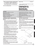
OWNER'S
MANUAL
ALUMINUM QUICK LIFTS
MODEL PEL-88A & PEL-100A
STEEL QUICK LIFTS
MODEL PEL-88, PEL-100 & PEL-400
CONTENTS
Warning and Safety Instructions ............................ 1
Chain Tension Adjustment for PEL-88 .................... 7
Receiving Instructions ............................................ 1
Parts for PEL-88 & PEL-100 ................................8-9
Loading Instructions ............................................... 2
Warning Labels for PEL-88 & PEL-100 ................ 10
Operating Instructions ............................................ 2
Chain Tension Adjustment for PEL-400 ................ 11 E
Electrical Diagram .................................................. 3
Parts for PEL-400 ............................................12-13
Troubleshooting Guide ........................................... 4
Parts for PEL-88A & PEL-100A ............................. 5
Warning Labels for PEL-88A & PEL-100A..............6
N
G
Warning Labels for PEL-400 ................................. 14 L
Limited Warranty ................................................... 15 I
S
H
WARNINGS & SAFETY INSTRUCTIONS
RECEIVING INSTRUCTIONS
Read owner's manual completely before operating unit!
Every unit is thoroughly tested and inspected prior
to shipment. However, it is possible that the unit may incur
damage during transit. If you see damage when unloading
make a note of it on the SHIPPER RECEIVER.
Remove all packing and strapping material, inspect for
damage. IF DAMAGE IS EVIDENT, FILE A CLAIM WITH
THE CARRIER IMMEDIATELY! Also, check the unit size,
type of power unit, etc., to ensure the unit is correct for
the intended application.
•
•
•
•
•
•
•
•
•
•
•
•
•
•
•
Never go under deck if there is load on unit.
Never operate unit unless you are watching it.
Stand clear from load when operating.
Do not operate unit unless all cover plates are securely
in place.
Do not continue to press the up-button if deck is not
raising.
Never exceed the maximum loading capacity
model PEL-88A & PEL-88 .................................. 175 lbs.
model PEL-100A & PEL-100 .............................. 125 lbs.
model PEL-400-57 & PEL-400-72 ....................... 400 lbs.
Load must be evenly distributed on deck to ensure
stability.
Consult factory for uneven loading.
Always operate unit on a level surface to ensure stability.
Always apply wheel brakes when unit is not being
moved.
Use caution in moving a loaded unit; avoid obstructions
and floor defects.
Remove load & disconnect power before working on unit.
Consult factory if adding or performing any modifications
to the original equipment.
Use only maintenance parts supplied or approved by the
manufacturer.
Make sure all operator safety labels are in place.
PEL-88A
PEL-100A
PEL-88
PEL-100
E
S
P
A
N
O
L
F
R
A
N
Ç
A
I
S
PEL-400-57
PEL-400-72
ALUMINUM & STEEL
QUICK LIFTS
1
LOADING INSTRUCTIONS
RESPONSIBILITIES OF OWNERS/USERS
It is the responsibility of the owner/user for the following:
The load capacity rating as inscribed on the
The unit must be inspected and maintained in
nameplate of your unit designates the net capacity, assuming 1)
accordance
with the guidelines in this manual.
the load is centered on the deck. This capacity must never
be exceeded, as permanent damage or injury may result.
2)
Any unit not in safe operating condition must be
removed from service until it is returned to proper
operating condition. All repairs and maintenance
OPERATING INSTRUCTIONS
must be performed by qualified personnel.
Position of the deck is controlled by the raise/
lower buttons on the touchpad. Speed is controlled from
3)
Unit may only be used by authorized personnel.
touchpad. A hand-held pendent control is optional.
All operators must have read and understood all
operating procedures and safety guidelines in this
Owner's Manual.
BATTERY RECHARGING & CARE
The battery is completely sealed and is,
therefore, maintenance-free and drip proof.
4)
The on-board charger operates on 115VAC and
requires a 3-wire (grounded) extension cord. It monitors
and reacts to the battery voltage, turning on the green
LED on top of the charger when the batteries are fully
charged.
A fully charged battery in good condition should read
12.65 volts. Wait at least 1/2 hour after the charger has
been turned off before checking the battery voltage.
PERIODIC MAINTENANCE INSTRUCTIONS
Operator must ensure that all safety features of
the unit are functioning properly before each use.
BE SURE ALL POWER IS OFF BEFORE ATTEMPTING
TO WORK ON THIS EQUIPMENT!
CAUTION: SERVICE WORK SHOULD BE PERFORMED ONLY BY
TRAINED & QUALIFIED PERSONNEL
Before
1)
2)
3)
4)
Charge the batteries for at least four hours prior
to first use. The charge interval of this unit will vary based
on the load and frequency of use. Since the majority of
applications require less than the maximum capacity and 5)
only intermittent use the actual time between charging will
only be found through experience. Also, the batteries
should be fully recharged each time. This will increase
the battery life.
Each Use Check For The Following:
Structural deformation of frame.
Proper operation of casters.
Unusual noise or binding.
Signs of wear, fatigue or loosening of any moving
parts and contact areas.
Check chain tension and adjust if applicable
(see chain tension adjustment section).
WARNING!
Over tensioning of the chain can
cause potential damage and/or injury.
• Charge unit at least once every two weeks.
• Leave plugged in when not in used. Disconnect battery
when storing the unit without power for more than one
month.
• The battery charger can be connected for extended
periods without damage to the batteries.
• Do not expose the lift or charger to rain or adverse
conditions.
6)
7)
Wear on the chain roller bushings.
Cover plates being securely in place.
DO NOT use if there are any of the above!
Monthly Inspections
1)
Check for frayed or loose wires.
2)
Clean off dirt and debris at all contact areas.
3)
Make sure all warning and safety labels are in
place and in good condition.
4)
Battery Condition
Ordering Replacement or Extra Parts
Our company takes pride in using the finest
available parts for our equipment. We are not responsible
for equipment failure resulting from the use of unapproved
replacement parts. To order replacement or extra parts for
your equipment contact Customer Service at the factory. In
any correspondence with the factory please include the
Serial Number which is inscribed on the nameplate of the
piece of equipment. Use only the part numbers provided in
this Owner's Manual.
2
ELECTRICAL DIAGRAM
FOR ALUMINUM & STEEL QUICKLIFTS
E
N
G
L
I
S
H
3
TROUBLESHOOTING QUICK REFERENCE GUIDE
FOR STEEL QUICKLIFTS
BE SURE ALL POWER IS OFF AND ALWAYS UNLOAD LIFT BEFORE ATTEMPTING TO
WORK ON THIS EQUIPMENT!
CAUTION: SERVICE WORK SHOULD BE PERFORMED ONLY BY TRAINED & QUALIFIED PERSONNEL
Observation
Possible Cause
Remedy
1.)
a.
Battery voltage low. (< 17)
(LED flashes • ••••)
a.
Charge battery.
b.
Bad wiring connection / broken
wire in circuit.
b.
Visually inspect wires, do continuity
checks with meter. Refer to electrical
diagram.
c.
Hand control's plug loose in the
touchpad socket.
c.
Push plug in place.
d.
Problem with moror/control (check for
LED flashes code on the touchpad).
d.
Consult diagnostics page.
e.
Unit is plugged into a 115V circuit.
e.
Unplug cord.
f.
CB or Fuse Blown
f.
Reset CB. Replace fuse.
a.
Battery voltage low.
a.
Charge battery.
b.
Platform overloaded.
b.
Check load; reduce if necessary.
*c.
Chain/Master link broken.
c.
Inspect chain, rollers, roller track, and
pulley assembly.
d.
Obstruction/jammed chain.
d.
Clear Obstruction.
a.
Battery voltage low.
a.
Charge battery.
b.
Platform roller bearing obstructed or is
binding.
b.
Inspect roller track for interference
or damage.
c.
The "platform raised" limit switch is
engaged too soon, or is bad
(PEL-400 only).
c.
Adjust the limit switch pulley spring's
tension; test switch with meter.
d.
Platform overloaded.
d.
Check load; reduce if necessary.
2.)
3.)
Power unit does not run when control
is operated.
Motor hums, platform would not move.
Unit turns off before reaching the fully
raised or lowered height.
4.)
Over/under temp cutback.
(LED flashes • •)
a.
Temperature > 92°C or < -25°C.
a.
Check load; reduce if necessary.
5.)
Pot high or low signal out of range.
(LED flashes • •• or ••• • or ••• •••••)
a.
b.
Throttle input wire open or shorted.
Throttle pot defective.
a.
b.
Verify wiring not damaged.
Consult factory.
6.)
Speed limit pot fault.
(LED flashes • •••)
a.
b.
Speed limit pot wire(s) broken or shorted.
Broken speed limit potentiometer.
a.
b.
Verify wiring if not damaged.
Consult factory.
7.)
Precharge Fault (LED ••• •••)
a.
Controller failure; low battery voltage.
a.
Charge battery.
8.)
Current sense voltage fault
(LED •••• ••)
a.
b.
Short in motor or in motor wiring.
Controller failure.
a.
b.
Verify motor wiring.
Consult factory.
9)
Motor Clicks
a.
Overloaded deck.
NOTE:
4
TOUCHPAD IS NOT SERVICEABLE.
DO NOT OPEN TOUCHPAD OR WARRANTY WILL BE VOID!!!
Delrin 1.36in. x 0.375in. aluminum roller assembly
42-527-001
ALUMINUM QUICKLIFT
MODEL PEL-88A & PEL-100A
WARNING LABEL IDENTIFICATION
For Aluminum Quick Lift • Model PEL-88A & PEL-100A
MAKE SURE ALL WARNING LABELS ARE IN PLACE!
*Product safety signs or labels should be
periodically inspected and cleaned by the
product users as necessary to maintain
good legibility for safe viewing distance ...
ANSI 535.4 (10.21)
Contact manufacturer for replacement
labels.
1
!
KEEP CLEAR
WHEN IN USE
2
!
WARNING
ADVERTENCIA
MANTENGASE
ALEJADO CUANDO SE
ESTA OPERANDO
!
AVERTISSEMENT
SE TENIR À
DISTANCE LORS DU
FONCTIONNEMENT
220
Charge unit at least every two weeks or leave plugged in when not in use.
Disconnect battery when storing unit without power for more than one month.
Cargue la unidad por lo menos cada dos semanas o enchupelo cuando no en
uso. Desconecte la batería al salvar la unidad sin carga por más de un mes.
Charger l'unité au moins deux fois par semaine ou laiser branché lorsque la
batterie lorsque l'unité est rangée et ne va pas fonctionner pendant plus d'un
mois.
VESTIL MANUFACTURING CORP. • Angola, IN 46703 USA
Phone (260) 665-7586 • Fax (260) 665-1339 • www.vestil.com
3
! WARNING
454
! AVERTISSEMENT
! ADVERTENCIA
DO NOT LOAD beyond rated capacity
NO CARGUE más allá de la capacidad tasada
NE PAS CHARGER au-delà de capacité
DISTRIBUTE LOAD EVENLY
DISTRIBUYA LA CARGA UNIFORMEMENTE
DISTRIBUER la charge régulièrement
SECURE AND LOWER load before moving
ASEGURE Y DESCIENDA la carga antes de mover
BIEN FIXER ET FAIRE DESCENDRE la charge avant de faire un mouvement
KEEP CLEAR when lowering
MANTENGASE ALEJADO cuando descienda
VOUS DEGAGER quand la charge descend
DO NOT sit or ride on cart
NO SE SIENTE o vaya en el carro
NE PAS VOUS ASSEOIR OU VOUS PROMENER sur le chariot
READ OWNERS MANUAL before using or working on this
equipment
LEA EL MANUAL DEL PROPIETARIO antes de usar o trabajar
en este equipo
LIRE LE GUIDE avant d’utiliser ou de travailler sur cet équipment
SHUT POWER off before working on this equipment
Apage el equipo antes de trabajar en èl
COUPER L’ALIMENTATION avant de faire des travaux sur cet équipement
589
4
PEL BATTERY CONNECTIONS
Charger
Charger
12V
Vertical on side
Curicut
BAT1 BAT2
3
Motor
The red wire (from T1 on the motor controller) connects
to one side of the circuit breaker. The other side of the
circuit breaker connects to the positive (+) post (red) on
BAT1.
The short jumper wire connects between the BAT1
negative (-) post (black) and BAT2 positive (+) post (red).
The unfused black wire (from T2 on the controller)
connects to the negative (-) post (black) on BAT2.
The charger plugs into the quick-connect harness located
on the end of the touchpad harness.
1
CONEXIONES DE LA BATERIA PEL
Cargador
Cargador
Baterias
Corto
El alambre rojo (del T1 en el control del motor) se conecta
a un lado del corto circuito. El otro lado del corto circuito
se conecta al poste (rojo) positivo (+) en BAT1.
El alambre de salto corto se conecta entre el poste (negro)
BAT1 negativo (-) y el poste (rojo) BAT2 positivo (+).
BAT1 BAT2
El alambre negro sin fusible (del T2 en el control) se
conecta al poste (negro) negativo (-) en el BAT2.
Localizacion
4
Inside
El cargador se enchufa en el equipo de conexión rápida
localizado en el extremo del equipo del telclado.
2
CONNEXIONS DE BATTERIE PEL
La
Chargeur
Batteries
Disjoncteur
1BAT 2BAT
Situa
Le fil rouge (de T1 sur le contrôleur du moteur) connecte
à un côté du disjoncteur. L’autre côté du disjoncteur
connecte à l’anode (borne positive) - rouge - de BAT1.
Le fil de liaison court connecte entre la cathode BAT1
(négative) - noir - et l’anode BAT2 (positive) - rouge.
Le fil noir sans fusible (de T2 sur le régulateur de charge)
connecte à la borne négative (noir) de BAT2.
Le chargeur de batterie branche à la distribution électrique
de la prise de courant située sur le bout de la touche à
effleurement.
399
6
STEEL QUICKLIFT
MODEL PEL-88 & PEL-100
INSTRUCTIONS FOR ADJUSTING THE LIFTING CHAINS TENSION
FOR STEEL QUICKLIFT • MODEL PEL-88
READ ALL INSTRUCTIONS BEFORE PROCEEDING!
Only trained and qualified service personnel should work on this equipment!
Lock out all potential energy sources before attempting this installation!
1)
2)
3)
4)
5)
6)
Remove any load that is on the machine and run the platform up until it is raised halfway up the mast.
Above the platform, locate the tensioning bolts (item 1; one at each end of the chain). Loosen the two jamb
nuts (item 2) by turning them in a counterclockwise direction. (Use a 7/16" wrench on the nut, and another
7/16" wrench to keep the chain from turning.) Loosen each until it is at the end of its respective chain tension
bolt.
Run the platform all the way up to the top of the mast until it stops moving.
Again using the 7/16" wrenches, turn the tensioning nuts (item 3) at each end of the chain until you can pull
the chain 3" away from the front of the mast at its midheight. Be sure to turn each nut about the same amount.
Lower the platform to the bottom of the mast, holding the "Lower" pushbutton for two seconds after the
platform hits bottom. If the chain "jumps" ont he sprocket, raise the platform up again. Tighten one of the
tensioning nuts another 1/2 turn (clockwise) and repeat the test.
Raise the platform back up halfway to the top of the mast and turn each of the jamb nuts until they are against
E
the tensioning nuts; then tighten each one wrench-tight.
N
G
L
I
S
H
1
3
PLATFORM
CARRIAGE
SIDE VIEW
2
CAUTIONS:
•
Double-check that both of the holding nuts have been adequately tightened down before placing the machine
back into service.
NOTES:
•
The chain's tension, the tension bolts, and the adjustment nuts should all be checked monthly.
7
STEEL QUICKLIFT
MODEL PEL-88 & PEL-100
PARTS DRAWING FOR STEEL QUICK LIFT
MODEL PEL-88 & PEL-100
46
1
16
8
2
15
3
39
4A, 4B
5
30
27
40
6A, 6B
25
29
28
27
22
7
8
24
26
18
10
38
14
11
21
8
19
20
8
15
16
17
12
STEEL QUICKLIFT
MODEL PEL-88 & PEL-100
PARTS IDENTIFICATION FOR STEEL QUICK LIFT
MODEL PEL-88 & PEL-100
ITEM NO. DESCRIPTION
Deck 24"W x 19"L
1
Screw & nylock nut,
2
Roller w/nylock nut, 5/16"-18UNC
3
Chain, no.35 x 127" lg (PEL-88)
4A
Chain no. 35 x 157" lg (PEL-100)
4B
Chain Connecting Link 41-1/2" pitch - 1/4 width
5
Front Cover (left side)
6A
Front cover (right side)
6B
Screw, 1/4"-20UNC x 3/4" (Type F, HWH)
7
Nylock nut, 3/8"-16UNC
8
Caster w/o brake
10
Plastic cap
11
Caster w/Brake (3 x 1-1/2)
12
Screw, 3/8-16 unc x 5/8 (FHSCS)
*13
Pulley bracket
14
Chain Roller (plastic)
15
Roller Bearing
16
Bolt 3/8-16 unc x 1-3/4" (HHCS)
17
Motor (Leeson)
18
Bolt & Nylock Nut 1/4-20 unc x 1-1/4
19
Back Cover
20
Sprocket 5/8" bore w/keyway & set screw
21
Battery
22
Battery Charger
24
Bolt & Nylock Nut & Washer - 1/8-27 unc x 4 (HHCS)
25
Spring Rod Bolt 1/2-13 unc x 8
26
Spring Rod Nut 1/2-13 unc
27
Washer 1/2 x 1-1/2 Fender Washer 2 plated
28
Spring
29
Handle Grip
30
Hand Control w/Coil Cord (optional)
*31
Bolt 3/8-16 unc x 2-1/4 (HHCS)
*35
Circuit Breaker
*37
Motor Controller
38
Touchpad
39
Power Inlet, 115V w/ 1-1/2" Nut
40
Bolt Control Mt. 8-32 unc x 1
*42
Bolts, Chain Adjusting 1/4-20 x 2 eyebolt
*44
Nuts, Chain Adjusting Bolt 1/4-20
*45
Chain Cover
46
Chain Cover Retaining Bolts (400 series only)
*47
Bolt (400 series only)
*48
Nut 8-32 unc
*49
Washer (400 series only)
*50
Nuts, Motor Controller 8-32 unc
*51
* Not Shown in Diagram
ENGINEER NO.
21-013-057
n/a
20-110-008
21-042-012
21-042-013
21-042-014
21-024-013
21-024-014
n/a
n/a
16-132-070
21-024-016
16-132-071
n/a
21-016-050
21-042-020
21-113-027
n/a
21-641-001
n/a
21-024-012
21-042-015
21-139-001
21-034-002
n/a
n/a
n/a
n/a
21-146-004
15-025-006
99-522-001
n/a
21-034-006
21-156-004
21-156-002
21-034-005
n/a
n/a
n/a
21-524-001
PART NO.
PEL-DCK
n/a
PEL-RNYKNT
PEL-CHN127
PEL-CHN157
PEL-CC
PEL-FCLS
PEL-FCRS
n/a
n/a
PEL-CSTR
PEL-PC
PEL-CSTBRK
n/a
PEL-PLYBRK
PEL-CHRLR
PEL-RLRBR
n/a
PEL-MTR
n/a
PEL-BC
PEL-SKT5/8
PEL-BATT
PEL-BATTCHR
n/a
n/a
n/a
n/a
PEL-SPG
PEL-HG
PEL-CNTL
n/a
n/a
n/a
n/a
n/a
PEL-MTRCNTL
PEL-TCHPD
PEL4-PINLT
n/a
n/a
n/a
PEL-CHNCVR
QTY
1
4
1
1
1
1
1
2
2
2
1
4
4
1
1
1
2
1
1
2
1
1
1
1
1
E
N
G
L
I
S
H
9
STEEL QUICKLIFT
MODEL PEL-88 & PEL-100
WARNING LABEL IDENTIFICATION
For Steel Quick Lift • Model PEL-88 & PEL-100
MAKE SURE ALL WARNING LABELS ARE IN PLACE!
1
!
WARNING
KEEP CLEAR
WHEN IN USE
!
ADVERTENCIA
MANTENGASE
ALEJADO CUANDO SE
ESTA OPERANDO
!
AVERTISSEMENT
SE TENIR À
DISTANCE LORS DU
FONCTIONNEMENT
2
*Product safety signs or labels should be periodically
inspected and cleaned by the product users as necessary
to maintain good legibility for safe viewing distance ...
ANSI 535.4 (10.21)
Contact manufacturer for replacement labels.
Charge unit at least every two weeks or leave plugged in when not in use.
Disconnect battery when storing unit without power for more than one month.
Cargue la unidad por lo menos cada dos semanas o enchupelo cuando no en
uso. Desconecte la batería al salvar la unidad sin carga por más de un mes.
Charger l'unité au moins deux fois par semaine ou laiser branché lorsque la
batterie lorsque l'unité est rangée et ne va pas fonctionner pendant plus d'un
mois.
VESTIL MANUFACTURING CORP. • Angola, IN 46703 USA
Phone (260) 665-7586 • Fax (260) 665-1339 • www.vestil.com
3
!
WARNING
! ADVERTENCIA
454
! AVERTISSEMENT
DO NOT LOAD beyond rated capacity
NO CARGUE más allá de la capacidad tasada
NE PAS CHARGER au-delà de capacité
DISTRIBUTE LOAD EVENLY
DISTRIBUYA LA CARGA UNIFORMEMENTE
DISTRIBUER la charge régulièrement
SECURE AND LOWER load before moving
ASEGURE Y DESCIENDA la carga antes de mover
BIEN FIXER ET FAIRE DESCENDRE la charge avant de faire un mouvement
KEEP CLEAR when lowering
MANTENGASE ALEJADO cuando descienda
VOUS DEGAGER quand la charge descend
DO NOT sit or ride on cart
NO SE SIENTE o vaya en el carro
NE PAS VOUS ASSEOIR OU VOUS PROMENER sur le chariot
READ OWNERS MANUAL before using or working on this
equipment
LEA EL MANUAL DEL PROPIETARIO antes de usar o trabajar
en este equipo
LIRE LE GUIDE avant d’utiliser ou de travailler sur cet équipment
SHUT POWER off before working on this equipment
Apage el equipo antes de trabajar en èl
COUPER L’ALIMENTATION avant de faire des travaux sur cet équipement
VESTIL MANUFACTURING CORPORATION • Angola, Indiana USA • Phone (260) 665-7586 • Fax (260) 665-1339 • [email protected] • www.vestil.com
589
4
PEL BATTERY CONNECTIONS
Charger
Charger
12V
Curicut
BAT1 BAT2
Motor
The red wire (from T1 on the motor controller) connects
to one side of the circuit breaker. The other side of the
circuit breaker connects to the positive (+) post (red) on
BAT1.
The short jumper wire connects between the BAT1
negative (-) post (black) and BAT2 positive (+) post (red).
The unfused black wire (from T2 on the controller)
connects to the negative (-) post (black) on BAT2.
The charger plugs into the quick-connect harness located
on the end of the touchpad harness.
CONEXIONES DE LA BATERIA PEL
Cargador
Cargador
Baterias
2
3
Corto
El alambre rojo (del T1 en el control del motor) se conecta
a un lado del corto circuito. El otro lado del corto circuito
se conecta al poste (rojo) positivo (+) en BAT1.
El alambre de salto corto se conecta entre el poste (negro)
BAT1 negativo (-) y el poste (rojo) BAT2 positivo (+).
BAT1 BAT2
El alambre negro sin fusible (del T2 en el control) se
conecta al poste (negro) negativo (-) en el BAT2.
Localizacion
El cargador se enchufa en el equipo de conexión rápida
localizado en el extremo del equipo del telclado.
CONNEXIONS DE BATTERIE PEL
1
La
Chargeur
Batteries
Disjoncteur
1BAT 2BAT
Situa
Le fil rouge (de T1 sur le contrôleur du moteur) connecte
à un côté du disjoncteur. L’autre côté du disjoncteur
connecte à l’anode (borne positive) - rouge - de BAT1.
Le fil de liaison court connecte entre la cathode BAT1
(négative) - noir - et l’anode BAT2 (positive) - rouge.
Le fil noir sans fusible (de T2 sur le régulateur de charge)
connecte à la borne négative (noir) de BAT2.
Le chargeur de batterie branche à la distribution électrique
de la prise de courant située sur le bout de la touche à
effleurement.
4
Inside
10
VESTIL MANUFACTURING CORPORATION
Angola, Indiana USA
Phone (260) 665-7586 • www.vestil.com Revision
399
1003
STEEL QUICKLIFT
MODEL PEL-400-57 & PEL-400-72
INSTRUCTIONS FOR ADJUSTING THE LIFTING CHAINS TENSION
FOR STEEL QUICKLIFT • MODEL PEL-400
READ ALL INSTRUCTIONS BEFORE PROCEEDING!
Only trained and qualified service personnel should work on this equipment!
Lock out all potential energy sources before attempting this installation!
1)
2)
3)
4)
5)
6)
Remove any load that is on the machine and run the platform up until it is raised halfway up the mast.
Above the platform, at each end of each chain, locate and turn the four holding nuts (closest to the chains;
item 1) in a counterclockwise direction. (Use a 3/4" wrench on the nut, and a 1/2" wrench to keep the chain
from turning.) Move the nuts as close as possible to the chains ends.
Run the platform all the way to the top of the mast until it stops moving.
Again using 3/4" and 1/2" wrenches, turn each of the four tensioning nuts (closest to the ends of the chain
tensioning bolts; item 2) clockwise until you can only pull the chain 2-1/2" away from the front of the mast at its
midheight. Be sure to turn each nut the same by measuring them for equal horizontal slack dimension.
Lower the platform to the mast, holding the "Lower" pushbutton for two seconds after the platform hits bottom.
If the chains "jump" on the sprockets, tighten the tensioning nuts another 1/2 turn (clockwise) and repeat the
test.
Raise the platform back up halfway to the top of the mast and turn each of the four holding nuts until they
E
touch against the tensioning brackets (item A), and then tighten each one wrench-tight.
N
G
L
I
S
1
H
A
2
A
2
1
CAUTIONS:
•
Take care to maintain equal tension on both of the lifting chains.
•
Double-check that all four of the holding nuts have been adequately tightened down before placing the
machine back into service.
NOTES:
•
The chain's tension, the tension bolts, and the adjustment nuts should all be checked monthly.
11
STEEL QUICKLIFT
MODEL PEL-400-57 & PEL-400-72
PARTS DRAWING FOR STEEL QUICK LIFT
MODEL PEL-400-57 & PEL-400-72
1
10
3
11
4
12
5
6
13
15
9
16
14
8
17
7
20
19
18
27
23
21
28
29
24
22
36
37
63
33
38
40
62
32
39
35
34
47
48
49
41
42
57
58
51
53
52
43
46
12
61
44
45
59
2
STEEL QUICKLIFT
MODEL PEL-400-57 & PEL-400-72
PARTS IDENTIFICATION FOR STEEL QUICK LIFT
MODEL PEL-400-57 & PEL-400-72
ITEM NO.
1
2
3
4
5
6
7
8
9
10
11
12
13A
13B
14
15
16
17
18
19
20
21
22
23
24
*25
26
27
28
29
*30
32
33
34
35
36
37
38
39
40
41
42
43
44
45
46
47
48
49
*50
51
52
53
54
*55
*56
57
58
59
60
61
62
63
*Not Shown in diagram
DESCRIPTION
Deck, 24"W x 20"L
Bolt, 10-32 x 1
Nut, 10-32
Deck, Steel Frame
Roller & Bushing
Pin, Roller
Spring Pin, 3/16 x 1-1/8
Bolt, 3/4-10 x 2-1/2
Nut, Plain 3/4-10
Top Sprocket Cover
Bolt, 1/4-20 x 1
Nylon Lock Nut, 1/4-20
Chain, #40 for PEL-400-57
Chain, #40 for PEL-400-72
S. Bolt 1/2 x 3 x 3/8-16
Spacer, 1/4 thick
Idler Sprocket
Spacer, 5/8 thick
Nylon Lock Nut, 3/8-16
Frame
Touch Pad
Bolt, 1/4-20 x 1
Handle Grips, Ergo
Cover, Front Right-Side
Screw, Self Tapping 1/2 long
Cover, Front Left-Side
Power Inlet, 115V w/ 1-1/2" Nut
Bolt, 8-32 x 4
Nut, 8-32
Charger
Circuit Breaker
Nut, 8-32
Washer #8
Screw, 8-32 x 1-3/4
Limit Switch
Nut, 1/2-13 Plain
Compression Spring
Washer, 1/2
Bolt, 1/2-13 x 6
12 Volt Battery
Gearbox Sprocket
Motor, 1 Hp w/ Gearbox
Nylon-Lock Nut, 3/8-16
Bolt, 3/8-16 x 1-1/4
Washer, 3/8 x 3/4
Cover
Nut, 1/4-20
Elevator Bolt, 1/4-20 x 1 1/4
S. Bolt, 1/2 x 1 3/4 x 3/8-16
Nylon-Lock Nut, 3/8-16
S. Bolt, 1/2 x 2 1/2 x 3/8-16
Spacer, 3/4 Thick
Nylon-Lock Nut, 3/8-16
Motor Controller
Bolt, 8-32 x 1
Nylon Lock-Nut, 8-32
S. bolt, 1/2 x 2 1/2 x 3/8 - 16
Spacer, 9/16 Thick
Nylon-Lock Nut, 3/8-16
Swivel Caster w/Brake
Swivel Casters, No Brake
Nut, 1/2-13
Lock Washer, 1/2"
ENGINEER NO.
21-013-064
24213
37015
21-513-035
21-527-003
01-112-013
64134
21-145-004
37633
21-024-029
11005
37018
21-042-017
21-042-021
26358
21-113-030
21-042-018
21-113-031
37024
n/a
21-156-002
11005
15-025-006
21-024-023
32028
21-024-024
21-034-005
27429
37012
21-034-007
21-034-004
37012
33072
27412
01-022-001
36110
21-146-005
33012
10896
21-139-002
21-042-019
21-641-002
37024
11107
33008
21-024-025
36102
22804
26353
37024
26356
21-113-033
37024
21-156-004
27402
37012
26356
21-113-032
37024
16-132-155
16-132-156
36110
33011
QTY
1
4
4
1
4
4
4
4
8
1
2
2
2
2
1
2
6
1
1
1
1
2
2
2
14
1
1
4
4
1
1
2
2
2
1
3
1
1
1
2
1
1
4
4
4
1
1
2
1
1
1
2
4
1
2
1
1
1
1
2
2
4
1
13
E
N
G
L
I
S
H
STEEL QUICKLIFT
MODEL PEL-400-57 & PEL-400-72
WARNING LABEL IDENTIFICATION
For Steel Quick Lift • Model PEL-400-57 & PEL-400-72
MAKE SURE ALL WARNING LABELS ARE IN PLACE!
1
!
WARNING
KEEP CLEAR
WHEN IN USE
2
!
!
ADVERTENCIA
AVERTISSEMENT
SE TENIR À
DISTANCE LORS DU
FONCTIONNEMENT
MANTENGASE
ALEJADO CUANDO SE
ESTA OPERANDO
*Product safety signs or labels should be periodically
inspected and cleaned by the product users as necessary
to maintain good legibility for safe viewing distance ...
ANSI 535.4 (10.21)
Contact manufacturer for replacement labels.
Charge unit at least every two weeks or leave plugged in when not in use.
Disconnect battery when storing unit without power for more than one month.
Cargue la unidad por lo menos cada dos semanas o enchupelo cuando no en
uso. Desconecte la batería al salvar la unidad sin carga por más de un mes.
Charger l'unité au moins deux fois par semaine ou laiser branché lorsque la
batterie lorsque l'unité est rangée et ne va pas fonctionner pendant plus d'un
mois.
VESTIL MANUFACTURING CORP. • Angola, IN 46703 USA
Phone (260) 665-7586 • Fax (260) 665-1339 • www.vestil.com
3
!
WARNING
454
! ADVERTENCIA
! AVERTISSEMENT
DO NOT LOAD beyond rated capacity
NO CARGUE más allá de la capacidad tasada
NE PAS CHARGER au-delà de capacité
DISTRIBUTE LOAD EVENLY
DISTRIBUYA LA CARGA UNIFORMEMENTE
DISTRIBUER la charge régulièrement
SECURE AND LOWER load before moving
ASEGURE Y DESCIENDA la carga antes de mover
BIEN FIXER ET FAIRE DESCENDRE la charge avant de faire un mouvement
KEEP CLEAR when lowering
MANTENGASE ALEJADO cuando descienda
VOUS DEGAGER quand la charge descend
DO NOT sit or ride on cart
NO SE SIENTE o vaya en el carro
NE PAS VOUS ASSEOIR OU VOUS PROMENER sur le chariot
READ OWNERS MANUAL before using or working on this
equipment
LEA EL MANUAL DEL PROPIETARIO antes de usar o trabajar
en este equipo
LIRE LE GUIDE avant d’utiliser ou de travailler sur cet équipment
SHUT POWER off before working on this equipment
Apage el equipo antes de trabajar en èl
COUPER L’ALIMENTATION avant de faire des travaux sur cet équipement
VESTIL MANUFACTURING CORPORATION • Angola, Indiana USA • Phone (260) 665-7586 • Fax (260) 665-1339 • [email protected] • www.vestil.com
589
4
PEL BATTERY CONNECTIONS
Charger
Charger
12V
Curicut
BAT1 BAT2
Motor
The red wire (from T1 on the motor controller) connects
to one side of the circuit breaker. The other side of the
circuit breaker connects to the positive (+) post (red) on
BAT1.
The short jumper wire connects between the BAT1
negative (-) post (black) and BAT2 positive (+) post (red).
The unfused black wire (from T2 on the controller)
connects to the negative (-) post (black) on BAT2.
The charger plugs into the quick-connect harness located
on the end of the touchpad harness.
CONEXIONES DE LA BATERIA PEL
Cargador
Cargador
Baterias
2
Corto
El alambre de salto corto se conecta entre el poste (negro)
BAT1 negativo (-) y el poste (rojo) BAT2 positivo (+).
BAT1 BAT2
3
El alambre rojo (del T1 en el control del motor) se conecta
a un lado del corto circuito. El otro lado del corto circuito
se conecta al poste (rojo) positivo (+) en BAT1.
El alambre negro sin fusible (del T2 en el control) se
conecta al poste (negro) negativo (-) en el BAT2.
Localizacion
El cargador se enchufa en el equipo de conexión rápida
localizado en el extremo del equipo del telclado.
1
CONNEXIONS DE BATTERIE PEL
La
Chargeur
Batteries
Disjoncteur
1BAT 2BAT
Situa-
Le fil rouge (de T1 sur le contrôleur du moteur) connecte
à un côté du disjoncteur. L’autre côté du disjoncteur
connecte à l’anode (borne positive) - rouge - de BAT1.
Le fil de liaison court connecte entre la cathode BAT1
(négative) - noir - et l’anode BAT2 (positive) - rouge.
Le fil noir sans fusible (de T2 sur le régulateur de charge)
connecte à la borne négative (noir) de BAT2.
Le chargeur de batterie branche à la distribution électrique
de la prise de courant située sur le bout de la touche à
effleurement.
VESTIL MANUFACTURING CORPORATION
Angola, Indiana USA
Phone (260) 665-7586 • www.vestil.com Revision
4
Inside
14
399
1003
LIMITED WARRANTY
ONE YEAR LIMITED WARRANTY. The manufacturer warrants for the original purchaser
against defects in materials and workmanship under normal use one year after date of purchase. (Not
to exceed 15 months after date of manufacture.) Any part which is determined by the manufacturer to
be defective in material or workmanship and returned to the factory, shipping costs prepaid, will be, as
the exclusive remedy, repaired or replaced at our option. Labor costs for warranty repairs and/or
modifications are not covered unless done at manufacturer’s facilities. Any modifications performed
without written approval of the manufacturer may void warranty. This limited warranty gives purchaser
specific legal rights which vary from state to state.
LIMITATION OF LIABILITY. To the extent allowable under applicable law, the manufacturer’s
liability for consequential and incidental damages is expressly disclaimed.
The manufacturer’s liability in any event is limited to, and shall not exceed, the purchase price paid.
Misuse or modification may void warranty.
WARRANTY DISCLAIMER. Our company has made a diligent effort to illustrate and describe
the products shown accurately; however, such illustrations and descriptions are for the sole purpose
of identification, and do not express or imply a warranty that the products are merchantable, or fit for
a particular purpose, or that the products will necessarily conform to the illustrations or descriptions.
The provisions of the warranty shall be construed and enforced in accordance with the
UNIFORM COMMERCIAL CODE and laws as enacted in the State of Indiana.
E
N
DISPOSITION. Our company will make a good faith effort for prompt correction or other G
adjustment with respect to any product which proves to be defective within the Limited Warranty. L
I
Warranty claims must be made in writing within said year.
S
H
SERVICE RECORD
DATE OF SERVICE:_____/_____/_____
DATE OF SERVICE:_____/_____/_____
WORK DONE BY:______________________________
WORK DONE BY:______________________________
SERVICE PERFORMED:__________________________________
SERVICE PERFORMED:__________________________________
_______________________________________________________
_______________________________________________________
_______________________________________________________
_______________________________________________________
DATE OF SERVICE:_____/_____/_____
DATE OF SERVICE:_____/_____/_____
WORK DONE BY:______________________________
WORK DONE BY:______________________________
SERVICE PERFORMED:__________________________________
SERVICE PERFORMED:__________________________________
_______________________________________________________
_______________________________________________________
_______________________________________________________
_______________________________________________________
DATE OF SERVICE:_____/_____/_____
DATE OF SERVICE:_____/_____/_____
WORK DONE BY:______________________________
WORK DONE BY:______________________________
SERVICE PERFORMED:__________________________________
SERVICE PERFORMED:__________________________________
_______________________________________________________
_______________________________________________________
_______________________________________________________
_______________________________________________________
15