1
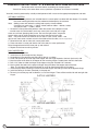
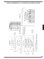
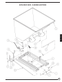
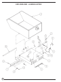
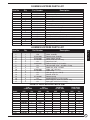
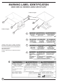
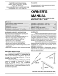
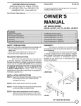
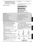
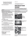
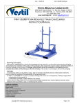
Revised 10-06
VESTIL MANUFACTURING CORPORATION
P.O. Box 507., Angola, IN 46703 USA
Phone (260) 665-7586 • Fax (260) 665-1339
E-mail: [email protected] • www.vestil.com
37-126-110
A company dedicated to solving ergonomic and material
handling problems since 1955.
Fork Truck Attachments
OWNER'S
MANUAL
Self-Dumping Steel Hoppers, D- & H-Series
Contents
Warnings and Safety Instructions ....................
Replacement Parts ..........................................
Receiving Instructions .....................................
Caster & Lid Assembly Instructions .................
Hopper Lid Cut Dimensions ............................
Operation Instructions .....................................
1
1
1
2
3
4
Exploded Structural Parts Dwg., D-Series ....... 5
Exploded Structural Parts Dwg., H-Series ....... 6
Hopper and Lid Parts List ................................. 7
Warning Label Identification ............................. 8
Routine Maintenance & Safety Checks ............ 9
Warranty ........................................................... 9
WARNINGS & SAFETY INSTRUCTIONS
RECEIVING INSTRUCTIONS
Ensure that all employees understand and follow the
following.
Every unit is thoroughly tested and inspected prior to
shipment. However, it is possible that the unit could incur
damage during transit.
•
•
•
•
•
•
•
•
•
Failure to read and understand this owner’s manual
before using or servicing the Hopper constitutes a
misuse of the product. All persons who will install, use, or
care for this product must be familiar with this material.
The load must be removed and the hopper secured
against unexpected movement before any work is
performed.
Ensure that all safety and warning labels stay in place
and are legible.
Do not use the dumper if any damage or unusual
noise is observed.
Watch the hopper carefully when it is being dumped or moved.
Ensure that the dumper is locked in place and secured
to the fork truck’s fork mast before transporting it or
raising it off the ground.
Do not perform any modifications to the dumper
without the manufacturer’s approval. Failure to receive
prior authorization for changes to the equipment could
void the warranty.
Maintenance and repairs are to be done only by
personnel qualified to perform the required work.
Use only factory-approved replacement parts.
Inspect the unit closely when it arrives. If you see evidence
of damage or rough handling to either the packaging or to
the product when it is being unloaded, immediately make a
note of it on the Bill Of Lading!
It is important that you remove the product’s packaging
upon its arrival to ensure that there is no concealed damage
or to enable a timely claim with the carrier for freight
damage.
Also verify that the product and its specifications are as
ordered.
E
S
P
A
N
O
L
D-Series Hopper
F
R
A
N
Ç
A
I
S
WHEN ORDERING REPLACEMENT PARTS
We take pride in using quality parts on the equipment we
manufacture. We are not responsible for equipment
problems resulting from the use of unapproved replacement parts.
To order replacement or spare parts for this equipment,
contact the factory.
In any communication with the factory please be prepared
to provide the dumper’s serial number, which is indicated
on the dumper’s dataplate.
E
N
G
L
I
S
H
H-Series Hopper
1
ASSEMBLY INSTRUCTIONS - D- & H-SERIES SELF-DUMPING HOPPERS
Review the entire instruction before assembling the dumper options.
Consult the factory in the event there are any questions or problems at the time of assembly.
¨ Assembly must be performed by suitably trained personnel with access to the appropriate equipment and tools.
OPTIONAL CASTERS
Note: Caster mounting brackets are included when the caster option is ordered with the dumper. For retrofits,
the caster mounting brackets must be welded to the dumper by the customer.
Note: Adding casters will reduce the rolling load capacity of some models.
Capacities are: semi-steel -- 1,200 lb / wheel; mold-on-rubber -- 600 lbs / wheel,
and; poly-on-steel -- 1,200 lb / wheel.
1. Locate the caster pad bracket positions under the corners of the dumper’s frame
-- a swivel caster is to be located at each rear corner (fork truck side) and a rigid
caster at each front (dumping side) corner. Be sure the rigid casters are parallel
to each other and will allow the dumper to roll away from the fork truck side.
Note: Only three casters are used on the 1/4 and 1/2 cubic yard H- series -- two
rigid at each front corner and one swivel in the middle of the rear side (under the hopper base).
2. Remove the bolt and nut from each caster pad bracket.
3. Place one end of a caster pad into the slot at the end of a caster pad bracket.
Raise the opposite end of the caster pad up and reinstall.
4. Repeat for the three remaining corners.
POLY HOPPER LIDS
Refer to the drawings below.
1. Install the main pin through the lid(s) hinge(s).
2. Assemble the hinge brackets onto the ends of the pin, as shown.
3. Place and square up the lid on top of the hopper, with the hinge oriented at the back (fork truck) side.
4. Mark the holes to be drilled in the hopper for the mounting hinges. Double-check the lid’s orientation.
5. Drill 11/32” holes and bolt the hinges to the hopper using the included 5/16” fasteners.
6. Mark and drill the holes for the prop-rod hinges along the side of the hopper, toward the front.
Note: The lid might need to be trimmed with tin snips to allow these hinges to fit properly.
7. Install the prop rod by inserting it into one of the front hinges and sliding it across to the opposite hinge.
8. Install the cotter pin and lock (if desired) in the prop rod.
o The main pin and the prop rod are identical, as are their hinges. There will be two left-side and two right-side
hinges.
D-STYLE HOPPERS
H-STYLE HOPPERS
2
HOPPER LID DIMENSIONS - D- & H-SERIES SELF-DUMPING HOPPERS
E
N
G
L
I
S
H
3
OPERATION INSTRUCTIONS - D- & H-SERIES SELF-DUMPING HOPPERS
Ensure that all employees involved in the operation of this hopper understand and follow these instructions!
The standard D-series and H-series models of self-dumping hoppers are suitable for use indoors and outdoors in
most common industrial and commercial locations. They are intended to be used in conjunction with a rider fork
truck to dump non-hazardous refuse into typical refuse containers.
The “D-” series dumper is a self-dumping hopper having a 70° dump angle. It can be operated by either a “bumper
release” on the front of the hopper or by a release cable held by the fork truck driver.
The “H-” series dumper is a low-profile self-dumping hopper having a 90° dump angle. It is operated by the fork truck
driver by means of a release cable.
•
•
•
Note: OSHA 29CFR, Chapter XVII, Part 1910.178 (a)(4) states, “Modifications and additions which affect capacity and
safe operation (of a fork truck) shall not be performed by the customer or user without manufacturer’s prior written
approval. Capacity, operation, and maintenance instruction plates, tags, or decals shall be changed accordingly. And
1910.178 (a)(5) states that “If (a fork) truck is equipped with front-end attachments other than factory installed attachments, the user shall request that the truck be marked to identify the attachments and show the approximate weight of
the truck and attachment combination at maximum elevation with load laterally centered.”
LOADING:
The load rating, in pounds, is shown on the dumper’s capacity label located on the rear (fork truck side) of the hopper.
Caution: Verify that the dumper is locked in the fully upright position before loading the hopper.
Warning: Do not exceed the dumper’s (and if portable, its casters’) load ratings or fill the hopper above the top of the
hopper’s sides. Injury to personnel or permanent damage to the equipment could result from overloading.
OPERATION:
Caution: Always carefully watch the hopper and its load when transporting or emptying it.
1. From the rear of the dumper, insert the fork truck’s forks into the dumper’s fork pockets. For the “D-” series, the fork
truck’s forks are to be inserted completely. For the “H-” series, they are to be inserted until they contact the fork tube
stops.
2. Secure the dumper to the fork truck’s fork carriage with the attached safety restraint. Wrap the restraint around a part
of
the fork carriage and attach the chain’s snap hook to the chain (through one of the chain links) with as little slack
as
possible.
3. Place the release cable within reach of the fork truck driver in preparation for dumping.
4. Move the front of the dumper into position at the side of the dumpster or refuse container.
5. Lift and tilt the fork truck mast forward until the dumper is at the appropriate height to allow the front of its frame to
make contact with the top of the container’s side.
Note: Allow clearance for the hopper to completely rotate forward without contacting any obstructions.
Warning: Keep all personnel clear of the dumper and the dumping area before releasing the hopper.
6. For either series, the release cable can be pulled from the fork truck operator’s position. For the “D-” series, the
operator can also drive the fork truck toward the refuse container until the dumper’s bumper release makes contact
with the container’s side.
Warning!: Never wrap the dumper’s release cable around any body part.
7. Tilt the fork truck mast back, then back away from the refuse container and slowly lower the dumper. The “D-” series
dumper will automatically rotate backward and lock in the upright position.
The “H-” series dumper must be lowered to the ground to return to the upright locked position.
Caution: Never use the dumper if any damage or unusual motion is observed, if it is in need of repairs, or if it seems to
be malfunctioning.
Notify your supervisor or maintenance personnel if you notice anything out of the ordinary.
Ensure all safety and warning labels stay in place and are legible. Refer to the manual’s label page.
4
EXPLODED VIEW - D-SERIES HOPPERS
E
N
G
L
I
S
H
5
EXPLODED VIEW - H-SERIES HOPPER
6
D-SERIES HOPPERS PARTS LIST
Item No.
Qty.
Part Number
1
2
3
4
5
6
7
8
9
10
11
12
13
14
15
16
17
18
1
1
1
1
1
1
1
1
1
1
1
2
4
1
3
2
2
1
N/A
N/A
37-537-005
37-537-003
37-112-007
37-537-006
37-112-006
01-112-009
37-145-005
37-025-002
37-145-004
37-145-003
A/L
A/L
A/L
A/L
A/L
37-146-005
Description
Base assembly
Chute assembly
Release plate assembly, frame mount
Release lever assembly
Main hinge pin
Release lever rod assembly
Bumper plate pin
Pin, 3/4” Ø x 1-5/16” long
Cable, 1/8” Ø x 48” long
Chute release handle
Chain, 5/16” x 48” long
Cable crimp
Spring pin, 3/16” Ø x 1-1/2” long
Cotter pin, 1/8” Ø x 2” long
Machine bushing, 1” I.D. x 10 Ga., 1-1/2” O.D.
Machine bushing, 1” I.D. x 18 Ga., 2” O.D.
Retaining ring, external for 3/4” Ø shaft
Spring, tension
H-SERIES HOPPERS PARTS LIST
Item No.
Qty.
Part Number
1
2
3
4
5
6
7
8
9
10
11
12
13
14
15
16
17
1
1
1
1
1
2
1
2
2
1
2
1
4
1
3
1
2
N/A
N/A
37-537-003
37-537-002
37-145-002
A/L
29-048-061
A/L
A/L
37-025-002
37-145-003
A/L
A/L
37-146-005
A/L
37-112-003
A/L
E
N
G
L
I
S
H
Description
Base assembly
Chute assembly
Release lever assembly
Chute release handle
Chain, 5/16” x 57-1/2” long
Quick-link, 5/16”
Rubber bumper, D- & H-series
Hex head bolt, 5/16” - 18 UNC x 2” long
Nylock nut, 5/16” - 18 UNC
Cable, 1/8” x 54” long
Cable crimp
Hitch pin clip, #11 (1/8” Ø)
Washer, 5/16” I.D.
Release spring
Machine bushing, 1” I.D. x 10 ga.
Main hinge pin, 13/16” Ø x 23-1/2” long
Spring pin, 3-16” Ø x 1-1/2” long
PLASTIC HOPPER LIDS PARTS LIST
Model
D-300
D-250
D-200
D-150
D-100
D-75
D-50
D-33
H-150
H-100
H-50
H-25
Lids
37-024-XXX
XXX
Qty.
-085-001
2
-085-002
2
-085-003
2
-085-004
1
-086-001
1
-086-002
1
-087-001
1
-087-002
1
-088-001
2
-088-002
2
-008-003
1
-008-004
1
Pins
37-012-XXX
Qty.
XXX
2
-035
2
-034
2
-033
2
-032
2
-031
2
-030
2
-029
2
-028
2
-037
2
-037
2
-036
2
-036
Left Hinge
37-016-XXX
XXX
Qty.
-034
2
-034
2
-034
2
-034
2
-034
2
-034
2
-034
2
-034
2
-032
2
-032
2
-032
2
-032
2
Right Hinge
37-016-XXX
XXX
Qty.
-033
2
-033
2
-033
2
-033
2
-033
2
-033
2
-033
2
-033
2
-032
2
-032
2
-032
2
-032
2
7
WARNING LABEL IDENTIFICATION
MAKE SURE ALL WARNING LABELS ARE IN PLACE!
D-Series Hopper
4
5
3
2
3
2
1
H-Series Hopper
1
1
208
2
375
*Product safety signs or labels should be
periodically inspected and cleaned by the product
users as necessary to maintain good legibility for
safe viewing distance . . .
ANSI 535.4 (10.21)
Contact manufacturer for replacement labels if
needed.
3
220
4
620
5
549
8
ROUTINE MAINTENANCE & SAFETY CHECKS FOR D- & H-SERIES HOPPERS
•
•
•
Warning: Care should be taken to identify all potential hazards and comply with applicable safety procedures
before beginning work.
Only qualified individuals trained to understand mechanical devices and their potential movements and hazards
should attempt troubleshooting and repair of this equipment.
Repairs must only be performed by suitably trained personnel with access to the
appropriate equipment and tools.
(A) Before each use inspect for the following:
1.) A frayed or damaged pull cable.
2.) Damage or structural deformation to the hopper, or the dumper’s frame.
3.) Proper latching of the locking mechanism.
4.) Unusual noise or binding while dumping, or evidence thereof.
5.) Evidence of fatigue or damage to the securing chain, its attachment point, or its quick-link.
(B) Inspect monthly for:
1.) Pivot point wear.
2.) Integrity of all pivot point pins.
3.) Looseness, wear, or damage to the casters’ bearings, mounting hardware, or surface material.
(Portable units only.)
4.) Proper functioning of the releasing mechanism.
5.) Unusual noises or movement when dumping.
6.) All the information, safety, and warning labels being in place and in good condition.
7.) The need to clean dirt and debris from areas that could affect the dumping motion.
PRODUCT WARRANTY
ONE YEAR LIMITED WARRANTY
The manufacturer warrants for the original purchaser against defects in materials and workmanship under normal use
one year after date of shipment (not to exceed 15 months after date of manufacture). Any part that is determined by the
manufacturer to be defective in material or workmanship and returned to the factory, shipping costs prepaid, will be, as
the exclusive remedy, repaired or replaced at our option. Labor costs for warranty repairs and/or modifications are not
covered unless done at manufacturer’s facilities or pre-approved in advance by the manufacturer. Any modifications
performed without written approval of the manufacturer may void warranty. This limited warranty gives purchaser specific
legal rights which vary from state to state.
All specifications are subject to change without notice.
LIMITATION OF LIABILITY
To the extent allowable under applicable law, the manufacturer’s liability for consequential and incidental damages is
expressly disclaimed. The manufacturer’s liability in any event is limited to, and shall not exceed, the purchase price
paid. Misuse or modification may void warranty.
Warranty does not cover labor or consequential damages including, but not limited to, business interruption costs, lost
profits, or lost business opportunities.
WARRANTY DISCLAIMER
The manufacturer has made a diligent effort to accurately illustrate and describe their products. However, such illustrations and descriptions are for the sole purpose of identification, and do note express or imply a warranty that the products are merchantable or fit for a particular purpose, or that the products will necessarily conform to the illustrations or
descriptions.
The provisions of the warranty shall be construed and enforced in accordance with the Uniform Commercial Code and
laws as enacted in the State of Indiana.
DISPOSITION
Our company will make a good faith effort for prompt correction or other adjustment with respect to any product that
proves to be defective within the Limited Warranty Period. Warranty claims must be made in writing within said year.
9
E
N
G
L
I
S
H