1
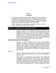
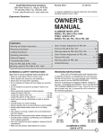
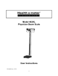
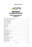
FM 5-472
C2
Change 2
Headquarters
Department of the Army
Washington, DC, 1 July 2001
Materials Testing
1.
Change FM 5-472, 27 October 1999, as follows:
Remove Old Pages
Insert New Pages
2-55 through 2-58
2-83 and 2-84
2-103 and 2-104
4-21 through 4-24
4-29 and 4-31
A-1
2-55 through 2-58
2-83 and 2-84
2-103 and 2-104
4-21 through 4-24
4-29 through 4-31
A-1
2.
A bar ( ) marks new or changed material.
3.
File this transmittal sheet in front of the publication.
DISTRIBUTION RESTRICTION: Approved for public release; distribution is unlimited.
By Order of the Secretary of the Army:
ERIC K. SHINSEKI
General, United States Army
Chief of Staff
Official:
JOEL B. HUDSON
Administrative Assstant to the
Secretary of the Army
0119105
DISTRIBUTION:
Active Army, Army National Guard, and US Army Reserve: To be distributed in accordance
with the initial distribution number 110133, requirements for FM 5-472.
FM 5-472/NAVFAC MO 330/AFJMAN 32-1221(I)
OVEN-DRY METHOD (ASTM D 2216-90)
The most accurate method of determining moisture content is the oven-dry
method. This method uses an oven with a temperature or thermostatic
control. For expedient determinations, soils are sometimes dried in a frying
pan or container heated by an external source, either a stove or an exhaust
manifold. However, heating most soils to excessive temperatures results in
chemical changes that may lead to errors in moisture-content results. Hence,
drying soils by an uncontrolled heat source is usually less accurate than
drying them in a thermostatically controlled oven.
PURPOSE
Perform this test to determine the moisture content of a soil sample to within
a desired percentage.
EQUIPMENT
The following items are necessary for this test method:
•
A laboratory oven.
•
Heat-resistant gloves.
•
A calculator.
•
Moisture-determination tares.
•
A grease pencil.
•
A balance scale sensitive to 0.01 gram.
•
DD Form 1205.
•
A pencil.
STEPS
Perform the following steps to determine the moisture content:
Step 1. Record all identifying information of the sample in blocks 1 through 5
of DD Form 1205 (see Figure 2-32, page 2-56).
Step 2. Label and weigh the clean, dry moisture-determination tares, and
record the weights on the form as the weight of the tare (line D).
Step 3. Obtain the required soil sample. Place it in the tare and cover it with
the lid.
•
When conducting this test as part of another test method, use the
specimen mass stated in that test method.
•
When conducting this test with no minimum specimen mass provided,
use the values provided in Table 2-5, page 2-57, depending on the
degree of accuracy of the reported water content.
Step 4. Weigh the soil sample and the tare to the nearest 0.01 gram. Record
the weight on the form as the weight of the tare and the wet soil (line A).
Step 5. Oven-dry the sample, with the moisture-determination tare lid
removed, at 110°C ± 5° until the sample weight becomes constant. Oven-drying
Soils 2-55
C2, FM 5-472/NAVFAC MO 330/AFJMAN 32-1221(I)
LE
P
M
SA
Figure 2-32. Sample DD Form 1205
2-56 Soils
C2, FM 5-472/NAVFAC MO 330/AFJMAN 32-1221(I)
Table 2-5. Recommended minimum test specimen for reporting water content
Maximum Particle Size
(100% Passing)
Standard Sieve Size
2.0 mm or less
4.75 mm
Minimum Moist Mass
for Reporting to ± 0.1%
Minimum Moist Mass
for Reporting to ± 1%
No. 10
20.0 g
20 g*
No. 4
100.0 g
20 g*
9.50 mm
3/8 in
500.0 g
50 g
19.00 mm
3/4 in
2.5 kg
250 g
37.50 mm
1 1/2 in
10.0 kg
1 kg
75.00 mm
3 in
50.0 kg
5 kg
* To be representative, not less than 20 grams shall be used.
time will vary depending on the type of soil, the size of the sample, and other
factors. For routine water-content determination, oven-dry a sample consisting
of clean sands and gravel for a minimum of 4 hours. For most other soils, a
minimum drying time of 16 hours is adequate.
Step 6. Remove the sample from the oven and replace the moisturedetermination tare lid. Allow the sample to cool until the tare can be handled
comfortably with bare hands.
Step 7. Weigh the dried soil sample and the tare. Record the weight as the
weight of the tare and dry soil (line B).
Step 8. Determine the weight of the water (Ww) by subtracting the weight of
the tare and dry soil (line B) from the weight of the tare and wet soil (line a).
Record the weight on the form (line C).
Step 9. Determine the weight of the dry soil (Ws) by subtracting the weight of
the tare (line D) from the weight of the tare and dry soil (line B). Record the
weight on the form (line E).
Step 10. Determine the water content (w), in percent, and record it using the
following formula:
WW
w = -------- × 100
WS
When determining the average water content, the individual tests must be
within ± 1 percent. Any individual tests that do not meet this requirement
will not be used (see Figure 2-32). If none of the individual tests meet this
requirement, then additional testing is required.
CALCIUM-CARBIDE-GAS PRESSURE METHOD (AASHTO T 217-1986)
CAUTION
The chemical reaction of calcium carbide with water produces acetylene gas which is extremely
flammable. Exercise extreme caution to avoid open flame when releasing the gas from the
speedy moisture tester. Perform the test in a well-ventilated area, as asphyxiation could occur if
performed in a confined area.
Soils 2-57
C2, FM 5-472/NAVFAC MO 330/AFJMAN 32-1221(I)
Use the calcium-carbide-gas pressure method to determine the moisture
content of a soil sample using the 26-gram speedy moisture tester to within
± 0.5 percent. If another tester is to be used, consult the user’s manual for
the tester before conducting the moisture-content determination.
PURPOSE
Perform this test to determine the moisture content of a soil sample to within
± 0.5 percent.
EQUIPMENT
Use the following items for the calcium-carbide-gas pressure test:
•
A calcium-carbide-pressure (speedy) moisture tester to hold a 26-gram
soil specimen.
•
A balance (readable to 0.1 gram).
•
Two 1 1/4-inch steel balls.
•
A cleaning brush and cloth.
•
A scoop (for measuring calcium-carbide reagent).
•
Calcium-carbide reagent.
STEPS
Perform the following steps to determine the soil’s moisture content:
Step 1. Weigh the soil sample to be tested, ensuring that it weighs exactly 26
grams. Place the soil sample in the tester’s body and add the two 1 1/4-inch
steel balls.
Step 2. Place three scoops (about 24 grams) of calcium carbide into the cap of
the tester and, with the pressure vessel in a horizontal position, insert the cap
into the pressure vessel. Seal the unit by tightening the clamp, taking care
that no carbide comes in contact with the soil until a complete seal is achieved.
Step 3. Raise the moisture tester to a vertical position so that the reagent in
the cap will fall into the pressure vessel.
Step 4. Shake the instrument vigorously in a rotating motion so that all lumps
are broken up to permit the calcium carbide to react with all available free
moisture. Shake the instrument in a rotating motion so that the steel balls
will not damage the instrument or cause soil particles to become embedded in
the orifice leading to the pressure diaphragm. Continue shaking at least 1
minute for granular soils and up to 3 minutes for other soils to permit
complete reaction between the calcium carbide and the free moisture. Allow
time for the dissipation of the heat generated by the chemical reaction.
Step 5. Hold the instrument in a horizontal position at eye level. Read the dial
when the needle stops moving. Record the dial reading as the percent of
moisture by wet mass.
Step 6. Point the cap of the instrument away from the operator and release the
gas pressure slowly. Empty the pressure vessel and examine the material for
lumps. If the sample is not completely pulverized, repeat the test using a new
2-58 Soils
C2, FM 5-472/NAVFAC MO 330/AFJMAN 32-1221(I)
stem. For the Type 151H hydrometer, the composite correction is the
difference between this reading and 1. For the Type 152H hydrometer, the
composite correction is the difference between the reading and 0.
e. Record the composite correction in block 11 of the form (Figure 2-43,
page 2-81).
f. Remove the hydrometer from the dispersing-fluid cylinder and place it
in a second cylinder filled with distilled water.
NOTE: From this point forward, all hydrometer readings will be
taken from the top of the meniscus.
Step 4. Perform the hydrometer test.
a. Record all identifying information for the sample, dispersing agent,
quantity used, and composite correction on the form.
b. Obtain the decimal fines from the original soil sample from DD Form
1206. Record it on DD Form 1794 (block 12).
c. Obtain the specific gravity of solids (Gs) of the soil sample from DD
Form 1208. Record it on DD Form 1794 (block 13).
d. Empty and thoroughly rinse the graduated cylinder containing the
dispersing solution from step 3.
e. Transfer the soaked sample to a dispersion cup, using distilled water to
wash any residue from the dish into the cup. Add distilled water to the
cup until the water surface is 3 inches below the top of the cup. Place the
cup in the dispersing machine and mix silts and sands for 5 minutes, lowplasticity clay for 7 minutes, and high-plasticity clay for 9 minutes.
f. Transfer the mixed solution to the clean 1,000-milliliter graduated
cylinder, using distilled water to wash any residue from the cup into the
cylinder. Add distilled water until the 1,000-milliliter volume mark is
reached.
g. Place the rubber cap over the open end of the cylinder. Turn the
cylinder upside down and back for a period of 1 minute to complete the
agitation of the slurry.
NOTE: The number of turns during this minute should be about
60, counting the turn upside down and back as two turns. If any
soil remains at the bottom of the cylinder during the first few
turns, it should be loosened by vigorous shaking of the cylinder
while it is in the inverted position.
h. After shaking the cylinder for 1 minute, place it on a level and sturdy
surface where it will not be disturbed. Remove the cap and start the
timer. Remove any foam that has formed during agitation by lightly
touching it with a bar of soap.
i. Immerse the hydrometer slowly into the liquid 20 to 25 seconds before
each reading. Take the actual hydrometer reading (R1) at 1 and 2
minutes of elapsed time. As soon as the 1- and 2-minute readings are
taken, carefully remove the hydrometer and place it in the second cylinder
of pure distilled water using a spinning motion. Record the reading on the
form (block 16).
Soils 2-83
C2, FM 5-472/NAVFAC MO 330/AFJMAN 32-1221(I)
j. Place a thermometer in the solution. Record the temperature reading,
in centigrade, to the nearest whole degree. Record on the form (block 18).
NOTE: It is extremely important to obtain accurate temperature
readings. The soil hydrometer is calibrated at 20°C. Variations in
temperature from this standard temperature produces inaccuracies
in the actual hydrometer readings. These inaccuracies will be
compensated for later during the computations.
k. Repeat steps 4i and 4j for the remainder of the required readings. Take
readings at the following intervals: 5, 15, and 30 minutes and 1, 2, 4, and
24 hours. After each reading, remove the hydrometer, place it in the
hydrometer of distilled water, and obtain the temperature reading.
Record the information on the form for each reading.
Step 5. Determine the dry weight of the sample by carefully washing all of the
sample into a preweighed pudding pan or dish (block 24). Oven-dry the
sample, allow it to cool, and determine and record the weight of the sample
and the pan or dish (block 23).
Step 6. Determine the weight of the dry soil by subtracting the weight of the
pan from the weight of the pan and dry soil. Record this information on the
form as the weight of the oven-dried soil (Ws) used for hydrometer testing
(block 25).
Step 7. Compute the results on DD Form 1794 (see Figure 2-43, page 2-81).
a. Column 17. Obtain the corrected reading (R) by adding the actual
hydrometer reading (column 16, R1) and the composite correction (block
11) and record the sum on the form.
R = R1 + composite correction
b. Column 19. Obtain the temperature versus specific gravity constant
(K) from Table 2-10. Record it on the form.
NOTE: Although typical specific-gravity values are listed in Table 210, there may be cases when a soil type falls above or below this range
of values. In these situations the value of K must be computed using
the following formula:
K =
where—
30η
η
--------------Gs – 1
η = coefficient of viscosity of the liquid (water) in poises (varies with
changes in temperature)
Gs = Specific gravity of solids for the material being tested
c. Column 20. Obtain the effective depth (L) for each corrected reading
(column 17) by using Table 2-11, page 2-86, and record on the form.
2-84 Soils
FM 5-472/NAVFAC MO 330/AFJMAN 32-1221(I)
EQUIPMENT
Perform the compaction test using the following items:
•
Cylinder molds (use one of the following molds, depending on the soil
sample being processed):
— Proctor mold; 4-inch (4.0-inch inside diameter and 4.584-inch
inside height having an internal volume of 0.0333 cubic foot),
having an extension collar (2.375 inches high) and a detachable
metal baseplate.
— CBR mold; 6-inch (6-inch inside diameter and 7-inch inside
height), having an extension collar (2 inches high) and detachable
metal baseplate. The mold should also have a metal spacer disk
(5.94-inch inside diameter and 2.416 inches thick) for use as a
false bottom in the mold during testing. When the spacer disk is in
place in the bottom of the mold, the internal volume of the mold
(excluding extension collar) shall be 0.075 cubic foot.
•
A compacting hammer or tamper. A sliding-weight type compacting
tamper, having a 2-inch-diameter steel striking face, a 10-pound mass,
and an 18-inch fall.
•
A No. 4 sieve.
•
A 3/8-inch sieve.
•
A 3/4-inch sieve.
•
A balance scale sensitive to 0.01 gram.
•
A balance scale sensitive to 1.0 gram.
•
Moisture tares.
•
A soils oven.
•
Filter paper.
•
A large spoon.
•
A large knife.
•
A steel straightedge.
•
A calculator.
•
DD Form 1210.
•
DD Form 1211.
The amount of material (field sample) required for the compaction test
depends on the test procedure being used and the field sample ’s moisture
content. The following are guidelines for the amount of soil required for the
test procedures:
•
Procedures A and B: Use about 35 pounds of dry soil or at least 50
pounds of moist soil.
Soils 2-103
C2, FM 5-472/NAVFAC MO 330/AFJMAN 32-1221(I)
•
Procedure C: Use about 75 pounds of dry soil or at least 100 pounds of
moist soil.
STEPS
Perform the following steps for the compaction test:
Step 1. Determine the test procedure to be used.
•
If the CBR design and tests are to be developed for this project, do not
use this method. See Section IX for procedures to be used for CBR.
•
If CBR is not a factor, determine the test procedure by evaluating the
gradation criteria of the procedures listed above (A, B, or C) with
column 17 (percent retained) on DD Form 1206.
Step 2. Prepare the soil sample.
a. Dry the sample until it can be easily crumbled under a trowel. Drying
may be done by air-drying or by using a drying apparatus, provided the
temperature of the sample does not exceed 60°C.
b. Break up the sample thoroughly, but not in such a manner as to reduce
the size of the individual particles.
c. Sieve the sample over a No. 4 (procedure A), 3/8-inch (procedure B), or
3/4-inch sieve (procedure C). When preparing the material by passing it
over the 3/4-inch sieve for compaction in the 6-inch mold, break up
aggregates sufficiently to at least pass the 3/8-inch sieve. This
facilitates the distribution of water throughout the soil in later mixing.
d. Separate from the sample 5 equal portions representing each point
desired on the compaction curve. The size of each sample for one mold is
about 2,700 grams for procedures A and B or 6,800 grams for procedure C.
Retain all excess soil sample.
Step 3. Adjust the water content.
NOTE: The water-content adjustments in this step are designed to
provide approximations of the OMC. In no way should these
approximations be used for or be interpreted as the actual moisture
content. Exact moisture determinations will be conducted in a later
step.
a. Establish the assumed or approximate OMC.
(1) Place exactly 100 grams of the excess soil sample in a dish.
(2) Add 5 milliliters of water to the sample and mix thoroughly. The
approximate OMC is typically achieved so that when the soil is
squeezed in the palm, it will adhere together on its own but it will
break cleanly into two separate pieces without either piece shattering
when bent. Usually this will be slightly less than the PL.
(3) Add small amounts of water (in milliliters), remembering to record
the amounts added, until the approximate OMC is achieved. Do not
confuse the approximate OMC with the actual moisture content of this
soil, which will be determined in a later step. For purposes of
conducting the test method, the approximate OMC will be the amount
2-104 Soils
C2, FM 5-472/NAVFAC MO 330/AFJMAN 32-1221(I)
•
A tamping rod (5/8 inch in diameter and 24 inches long with a rounded
end).
•
A sample of plastic (fresh) concrete.
•
Water.
•
Oil.
•
Rags.
•
A pail.
•
A mixing pan (from the concrete test set).
•
A kitchen scoop.
•
Paper.
•
A pencil.
•
A rubber mallet.
STEPS
There are many different air-entrainment meters currently fielded and
replacements of old equipment may not be the same. For this reason, it is
recommended that the steps outlined in the manufacturer’s user’s manual be
followed.
SECTION IV. FLEXURAL-STRENGTH TEST (MODULUS OF RUPTURE)
The flexural strength of hardened concrete is measured by using a simple
concrete beam and third-point loading mechanism. The flexural strength is
determined by calculating measured breaks of the beam and is expressed as a
modulus of rupture in psi.
TEST BEAMS
Beam forms for casting test beams from fresh concrete are available in many
sizes. The most commonly used size is 6 x 6 x 21 inches. Although equipment
for obtaining sawed specimens may not be available, the test may be
performed on beams sawed from existing concrete structures for evaluation
purposes.
FORMING THE BEAMS (ASTM C 192-90A)
Assemble a standard 6- x 6- x 21-inch concrete-beam mold and lightly oil the
inside. Fill the mold with two layers of concrete from the production batches,
each about 3 inches deep. Consolidate each layer by rodding, using one stroke
per 2 square inches (63 per layer), evenly distributed over the layer’s surface.
Tap the sides lightly 10 to 15 times with a rubber mallet to close the voids left
by rodding. Lightly spade the concrete along the mold’s sides with a trowel to
help remove surface voids. When rodding the second layer, penetrate the first
layer about 1/2 inch. Strike off the top surface with a straightedge, and finish
it with a wood or magnesium float.
Concrete 4-21
FM 5-472/NAVFAC MO 330/AFJMAN 32-1221(I)
TAKING THE SPECIMENS
Take test specimens at least once for each 100 cubic yards or fraction thereof,
for each class of concrete placed in any one day, or as directed in the project
specifications. Make at least three specimens for each test age and mixture
design being evaluated in the lab. Additional specimens may be made for
future testing. Test ages are normally 14 and 28 days for flexural-strength
tests. For testing field-placed concrete, a minimum of two specimens for each
test age is required.
CURING THE BEAMS
Place a suitable identifying label on the finished surface of the specimens.
Cover the entire specimens—still in the mold—with a double thickness of wet
burlap. Ensure that the specimens remain on site and are undisturbed for an
initial curing period (the first 16 to 48 hours after molding). After this curing
period, move them to the testing laboratory and remove them from the molds
for further curing. The most satisfactory curing range for concrete is 68° to
86°F, with 73.4°F being the most favorable temperature. Moist-cure the
beams in saturated lime water, totally submerged in a wet-tank humidity
room, or keep them wet until they are tested.
FLEXURAL-STRENGTH TEST (ASTM C 78-94)
Perform this test to determine the flexural strength (modulus of rupture) of
the test specimen to + 10 psi. Record the specimen identification, modulus of
rupture, any defects noted, and specimen’s age.
EQUIPMENT
Use the following items to perform this test in a laboratory environment:
•
The flexural-strength test apparatus.
•
A concrete beam, 6 x 6 x 21 inches.
•
A measuring tape.
•
A stopwatch.
•
Pens.
•
Pencils.
•
Paper.
•
Safety goggles.
•
A proving-ring with proving-ring calibration and constant.
•
Specimen identification.
•
A calculator.
STEPS
Perform the following steps to determine the flexural strength. Wear safety
goggles throughout this test.
Step 1. Assemble the test apparatus and check for functional operation (see
Figure 4-5).
4-22 Concrete
C2, FM 5-472/NAVFAC MO 330/AFJMAN 32-1221(I)
Apply load here
Loading
Steel rod
Specimen
Steel ball
(d)
in
Steel rod
Steel ball
Length of span
Figure 4-5. Apparatus for flexural-strength test
Step 2. Measure the length of span and record the measurement on a piece of
paper. The length of span is determined by measuring the distance from
center to center of the two loading points (or supports) on the base of the
apparatus (see Figure 4-5). The normal length of specimen is 21 inches and
the normal length of span is 18 inches.
Step 3. Place the specimen in the tester and bring the loading surface into
contact with the test specimen (see Figure 4-5).
Step 4. Zero the gauge. Some apparatus are equipped with a hydraulic pump
and corresponding gauge while others are equipped with a loading jack and
proving ring.
Step 5. Apply a load at a continuous rate that constantly increases the
extreme fiber stress between 125 and 175 psi per minute. This is an
approximate load of 1,500 to 2,100 pounds per minute.
Step 6. Obtain the total load, in pounds, at the time of specimen failure, and
record the weight on the paper provided. On machines equipped with
hydraulics, take the reading directly from the gauge. For machines equipped
with a proving ring, this reading is the product of the dial-gauge reading and
the proving-ring constant.
Step 7. Determine and record the width and depth of the specimen, in inches,
at the point of failure (normally 6 x 6 inches).
Step 8. Determine the point of failure in the specimen, and calculate the
modulus of rupture. If the specimen fails outside the middle third of the span
length by more than 5 percent of the total span length, then the specimen is
Concrete 4-23
C2, FM 5-472/NAVFAC MO 330/AFJMAN 32-1221(I)
considered unusable and should be discarded (not more than 0.9 inches for an
18-inch span (18 x 0.05 = 0.9).
a. Use the following formula to calculate the modulus of rupture if the
specimen fails within the middle third of the span length:
where—
P×L
R = --------------b × d2
R = modulus of rupture, in psi
P = applied load, in pounds
L = length of span, in inches
b = width of specimen at failure point, in inches
d = depth of specimen at failure point, in inches
b. Use the following formula to calculate the modulus of rupture if the
specimen fails outside the middle third of the length of span by not more
than 5 percent of the span length:
3P × a
R = ---------------b × d2
where—
R = modulus of rupture, in psi
P = applied load, in pounds
b = width of specimen at failure point, in inches
d = depth of specimen at failure point, in inches
a = distance between the failure point and the nearest support, measured
along the centerline of the bottom of the specimen, in inches
Step 9. Record the following information about the test (some information
may be unavailable at the time of the test):
4-24 Concrete
•
Specimen’s identification number.
•
Average width to the nearest 0.05 inch.
•
Average depth to the nearest 0.05 inch.
•
Span length, in inches.
•
Maximum applied load, in pounds.
•
Modulus of rupture, to the nearest 10 psi.
•
Curing history (how the specimen was cured) and apparent moisture
content of the specimen at the time of the test.
•
Any defects noted in the specimen.
•
The age of the specimen.
FM 5-472/NAVFAC MO 330/AFJMAN 32-1221(I)
•
A ruler accurate to 0.01 inch.
•
Calipers with at least a 6-inch opening.
•
Paper.
•
Pencils.
•
Safety goggles and protective apron.
•
A face shield.
•
Oil.
•
Rags.
•
A calculator.
•
A concrete compression tester with a 250,000-pound capacity.
•
A hammer (ball peen or carpenter’s).
STEPS
Perform the following steps to determine the concrete cylinder’s compressive
strength:
Step 1. Prepare the concrete cylinder.
NOTE: If rubber-filled metal is used, go to step 1j.
a. Melt the capping compound in the melting pot. Ensure that you melt
enough compound to make several caps.
b. Clean and lightly oil the baseplate of the capping apparatus.
c. Set the baseplate into the capping-apparatus stand.
d. Pour a small amount of the heated (liquid) capping compound into the
baseplate.
e. Position the cylinder at midheight against the backrest of the capping
apparatus. Slowly lower the cylinder into the baseplate while keeping the
cylinder flush against the backrest. If the cylinder is not kept flush with
the backrest while capping, the caps and the cylinder will not be
perpendicular, and a proper break will not occur.
f. Remove the cylinder from the capping apparatus once the capping
compound has solidified.
g. Inspect the cap for uniformity and defects. If you see any defects,
remove the cap and recap the cylinder; then return to step 1a.
h. Repeat steps 1a through 1g for the uncapped end of the cylinder.
i. Determine and record the average diameter of the concrete cylinder.
The average diameter is the average of two diameters taken perpendicular
to each other at midheight of the cylinder.
j. Clean and examine the bearing surface of the steel cap (if used) for
nicks, gouges, and warping. Check the rubber inserts for tears, rips, cuts,
and gouges. Replace them if they are in poor condition or if the maximum
Concrete 4-29
C2, FM 5-472/NAVFAC MO 330/AFJMAN 32-1221(I)
number of serviceable uses has been exceeded. Place the steel cap firmly
on the cylinder’s ends.
Step 2. Prepare the compression tester (see Figure 4-6).
a. Clean the tester’s bearing plates (loading surfaces).
b. Check the tester for proper operation.
c. Set the gauge to zero.
Step 3. Place the capped cylinder into the compression tester and center it on
the bearing plates. Secure the protective cage around the cylinder.
Step 4. Apply the test load at a rate of 20 to 50 psi per second, not to exceed 50
psi per second (50 psi per second is about equivalent to a load [gauge reading]
of 1,400 pounds per second).
Step 5. Read the gauge and record the load applied at the time of failure.
Step 6. Inspect the broken cylinder and record the following information:
•
Identification number.
•
Diameter.
•
Cross-sectional area, in square inches.
•
Maximum load applied, in pounds.
•
Compressive strength, calculated to the nearest 10 psi.
•
Type of break (see Figure 4-7).
•
Defects in either specimen or caps.
•
Age of specimen.
Step 7. Calculate and record the compressive strength of the cylinder using
the following formula:
P
Compressive strength = --A
where—
P = load at time of failure, in pounds
A = π r2
4-30 Concrete
C2, FM 5-472/NAVFAC MO 330/AFJMAN 32-1221(I)
Figure 4-6. Compression tester
Cone
Cone and split
Cone and shear
Shear
Columnar
Figure 4-7. Types of fractures
Concrete 4-31
C2
Appendix A
Metric Conversion Chart
This appendix complies with current Army directives which state that the
metric system will be incorporated into all new publications. Table A-1 is a
conversion chart.
Table A-1. Metric conversion chart
Metric to English
Multiply
By
English to Metric
To Obtain
Multiply
By
To Obtain
Length
Centimeters
0.0394
Inches
Inches
2.54
Centimeters
Meters
Meters
3.28
Feet
Feet
0.0305
Meters
1.094
Yards
Yards
0.9144
Meters
Kilometers
0.621
Miles (stat)
Miles (stat)
1.5609
Kilometers
Kilometers
0.540
Miles (naut)
Miles (naut)
1.853
Kilometers
Millimeters
0.039
Inches
Inches
25.40
Millimeters
Area
Square
centimeters
0.1550
Square inches
Square inches
6.45
Square
centimeters
Square meters
10.76
Square feet
Square feet
0.0929
Square meters
Square meters
1.196
Square yards
Square yards
0.836
Square meters
16.39
Cubic
centimeters
Volume
Cubic
centimeters
0.610
Cubic inches
Cubic inches
Cubic meters
35.3
Cubic feet
Cubic feet
0.0283
Cubic meters
Cubic meters
1.308
Cubic yards
Cubic yards
0.765
Cubic meters
Milliliters
0.0338
US liq ounces
US liq ounces
29.6
Milliliters
Liters
1.057
US liq quarts
US liq quarts
0.946
Liters
Liters
0.264
US liq gallons
US liq gallons
3.79
Liters
Weight
Grams
0.0353
Ounces
Ounces
28.4
Grams
Kilograms
2.20
Pounds
Pounds
0.454
Kilograms
Metric tons
1.102
Short tons
Short tons
0.907
Metric tons
Metric tons
0.984
Long tons
Long tons
1.016
Metric tons
Subtract 32
and multiply by
0.5556
Celsius
Temperature
Celsius
Add 17.8 and
multiply by 1.8
Fahrenheit
Fahrenheit
Metric Conversion Chart A-1