1
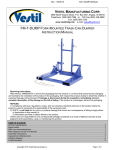
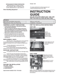
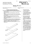
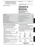
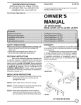
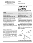
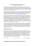
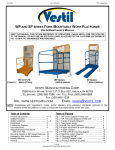
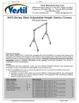
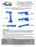
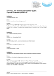
0813 Rev. 1/5/15 TRI, manual.doc VESTIL MANUFACTURING CORP. 2999 North Wayne Street, P.O. Box 507, Angola, IN 46703 Telephone: (260) 665-7586 -or- Toll Free (800) 348-0868 Fax: (260) 665-1339 www.vestilmfg.com e-mail: [email protected] TRI-SERIES TRIPODS INSTRUCTION MANUAL Receiving instructions: After delivery, IMMEDIATELY remove the packaging from the product in a manner that preserves the packaging and maintains the orientation of the product in the packaging; then inspect the product closely to determine whether it sustained damage during transport. If damage is discovered during the inspection, immediately record a complete description of the damage on the bill of lading. If the product is undamaged, discard the packaging. NOTES: 1) Compliance with laws, regulations, codes, and non-voluntary standards enforced in the location where the product is used is exclusively the responsibility of the owner/end-user. 2) VESTIL is not liable for any injury or property damage that occurs as a consequence of failing to apply either: a) The instructions in this manual; or b) Information provided on labels affixed to the product. Neither is VESTIL responsible for any consequential damages sustained as a result of failing to exercise sound judgment while assembling, installing, using or maintaining this product. Table of Contents Hazard identification: explanation of signal words………………………………………………………………………. 2 Safety Guidelines…………………………………………………………………………..…………………….…………. 2 Exploded parts diagrams and bills of materials………………………………………………………………………….. 3 – 6 Product specifications………………………………………………………………………………………………………. 7 Installation instructions……………………………………………………………………………………………………... 7 Assembly instructions………………………………………………………………………………………………………. 7 – 8 Using the tripod……………………………………………………………………………………………………………… 9 Inspections & Maintenance Recommendations…………………………………………………………………………. 9 Label placement diagram ………….. …………………………………………………………....................................... 9 Limited warranty…………………………………………………………………………………………………………….. 10 Copyright 2013 Vestil Manufacturing Co. Page 1 of 10 0813 Rev. 1/5/15 TRI, manual.doc HAZARD IDENTIFICATION: explanation of signal words This manual uses SIGNAL WORDS to indicate the likelihood of personal injuries, as well as the probable seriousness of those injuries, if the product is misused in the ways described. Other signal words call attention to uses of the product likely cause property damage. The signal words used appear below along with the meaning of each word: Identifies a hazardous situation which, if not avoided, WILL result in DEATH or SERIOUS INJURY. Use of this signal word is limited to the most extreme situations. Identifies a hazardous situation which, if not avoided, COULD result in DEATH or SERIOUS INJURY. Indicates a hazardous situation which, if not avoided, COULD result in MINOR or MODERATE injury. Identifies practices likely to result in product/property damage, such as operation that might damage the product. Safety Guidelines VESTIL strives to identify foreseeable hazards associated with the use of its products. However, material handling is inherently dangerous and no manual can address every conceivable risk. The end-user ultimately is responsible for exercising sound judgment at all times. Electrocution might result if any part of the tripod or a load suspended from it contacts electrified wires. If this product is used improperly or carelessly, the user and/or bystanders might sustain serious personal injuries or even be killed. Each person who assembles, uses or maintains this tripod should read and understand the entire manual before installing, using or servicing the product for the first time. Failure to do so is a misuse of the product. If you do not understand an instruction, ask your supervisor for clarification. To reduce the likelihood of injury: Read the manual to refresh your understanding of proper use and maintenance procedures when necessary. DO NOT attempt to resolve any problem with the product unless you are both authorized to do so and certain that it will be safe to use afterwards. Inspect the product before each use, as described in “Inspections & Maintenance Recommendations” on p. 9, to confirm normal condition. DO NOT use the product if any unusual noise or movement is observed. If a malfunction occurs, remove the unit from service and notify your supervisor & maintenance personnel about the issue. DO NOT exceed the capacity of the tripod (see “Product specifications” table on p. 7 and “Label placement diagram” on p. 9). DO NOT stand, or allow other persons to stand, reach, or crawl beneath any elevated part of the tilter. DO NOT modify the tripod or any component of the lifter in any way UNLESS you first obtain written approval from Vestil. Unauthorized modifications automatically void the Limited Warranty (p. 10) and might make the device unsafe to use. DO NOT use the tripod UNLESS all product labels (see “Label placement diagram” on p. 9) are readable and undamaged. Proper use, maintenance, and storage are essential for this product to function properly. o Always use this product in accordance with the instructions in this manual and consistent with any training relevant to hoists and rigging used in conjunction with this product. o Keep the product clean & dry. Periodically lubricate moving parts. Copyright 2013 Vestil Manufacturing Co. Page 2 of 10 0813 Rev. 1/5/15 TRI, manual.doc FIG. 1: TRI-SA Exploded Parts Diagram & Bill of Materials Item no. 1 2 3 4 5 6 7 8 9 10 11 12 Part no. Description 28-014-155 28-113-010 28-014-156 28-514-083 28-014-114 66125 36116 33012 66123 45286 28-145-008 28-145-015 Top casting Beveled washer Foot casting Outer leg tube Inner leg tube ½ in. x 6 in. clevis pin ¾ in. – 10 hex nut Plain USS flat washer ½ x 4½ clevis pin 1 /8 in. x 25/8 in. #11 hitch pin ¾ in. x 6 in. eyebolt 3 /8 in. x 52 in. chain Copyright 2013 Vestil Manufacturing Co. Quantity Page 3 of 10 1 1 3 3 3 6 2 6 3 9 1 3 0813 Rev. 1/5/15 TRI, manual.doc FIG. 2: TRI-SF Exploded Parts Diagram & Bill of Materials Item no. 1 2 3 4 5 6 7 8 9 10 Part no. 28-014-155 28-514-084 28-014-156 28-113-010 28-145-008 36116 45286 66125 33012 28-145-015 Copyright 2013 Vestil Manufacturing Co. Description Top casting Outer leg tube Foot casting Beveled washer ¾ in. x 6 in. eyebolt ¾ in. – 10 hex nut 1 /8 in. x 25/8 in. #11 hitch pin ½ in. x 6in. clevis pin Plain USS flat washer 3 /8 in. x 52 in. chain Page 4 of 10 Quantity 1 3 3 1 1 2 6 6 6 3 0813 Rev. 1/5/15 TRI, manual.doc FIG. 3: TRI-AA Exploded Parts Diagram & Bills of Materials Item no. 1 2 3 4 5 6 7 8 9 10 11 12 13 Part no. Description 28-014-155 28-514-118 28-014-156 33012 36116 45286 66125 28-113-010 28-145-008 28-014-182 66123 28-145-015 45214 Top casting Outer leg tube Foot casting Plain USS flat washer ¾ in. – 10 hex nut 1 /8 in. x 25/8 in. #11 hitch pin ½ in. x 6 in. clevis pin Beveled washer ¾ in. x 6 in. eyebolt Inner leg tube ½ in. x 4½ in. clevis pin 3 /8 in. x 52 in. chain 5 /16 in. quick link Copyright 2013 Vestil Manufacturing Co. Quantity Page 5 of 10 1 3 3 6 2 9 6 1 1 3 3 3 3 0813 Rev. 1/5/15 TRI, manual.doc FIG. 4: TRI-AF Exploded Parts Diagram & Bill of Materials Item no. 1 2 3 4 5 6 7 8 9 10 Part no. 28-014-155 28-514-117 28-113-010 28-014-156 28-145-008 36116 45214 45286 66125 28-145-015 Copyright 2013 Vestil Manufacturing Co. Description Top casting Outer leg tube Beveled washer Foot casting ¾ in. x 6 in. eyebolt ¾ in. – 10 hex nut 5 /16 in. quick link 1 /8 in. x 25/8 in. #11 hitch pin ½ in. x 6 in. clevis pin 3 /8 in. x 52 in. chain Page 6 of 10 Quantity 1 3 1 3 1 2 3 6 6 3 0813 Rev. 1/5/15 TRI, manual.doc Product specifications Dimensions and other specifications appear in the table below: Model Description Eyelet height Capacity TRI-SA Leg length adjustable 8½ft. to 13½ft. 2,000 TRI-SF Fixed leg length 8½ft. 2,000 TRI-AA Leg length is adjustable 8½ft. to 13½ft. 1,000 TRI-AF Fixed leg length 8½ft. 1,000 Net weight 285 lb. 129.5 kg 285 lb. 129.5 kg 215 lb. 97.7 kg 215 lb. 97.7 kg Assembly instructions [refer to the exploded part diagram for the appropriate model] To assemble the tripod, perform the following steps: 1. Pin the upper end each outer leg tube to the top casting with 6in. clevis pins (part no. 66125). [NOTE: A handle is welded to the lower end of each outer leg tube.] Secure the clevis pins with hitch pins. FIG. 5: Pin outer leg tubes to top casting Eyebolt (see step 2) ¾in. - 10 hex nuts Hitch pin Beveled washer 6in. clevis pin Outer leg tube 1 /8 in. x 25/8 in. #11 hitch pin Handle Top Bottom Outer leg tube Beveled washer ½ in. x 6in. clevis pin Top casting Copyright 2013 Vestil Manufacturing Co. Page 7 of 10 0813 Rev. 1/5/15 TRI, manual.doc 2. Install the eyebolt. Feed the bolt up through the hole in the center of the top casting. As shown in FIG. 5 on p. 7, slide the beveled washer over the end of the bolt with the larger side facing up, and secure the bolt in place with hex nuts. Eyebolt 3. If your tripod has adjustable legs (models TRI-SA & TRI-AA), pin the inner leg tubes to the outer leg tubes next. Notice that the inner leg tubes have a series of pin holes along the length of the tube. The lower end of each inner leg tube has 2 additional holes for pins that connect to the feet. FIG. 6A FIG. 6: Assembly Quick link Collar FIG. 6B: Pin inner & outer leg tubes together Outer leg tube FIG. 6C: Attach foot castings Inner leg tube Hitch pin ½ in. x 6in. clevis pin 4. Attach the foot castings to the lower end of the leg tubes with ½ in. x 4½in. clevis pins. Secure the pins with hitch pins. 5. Select the appropriate foot casting orientation for the usage environment. Pivot the foot castings to present either a spiked or smooth face. FIG. 7A: Use spiked face on loose ground FIG. 7B: Use the smooth face on packed or improved surfaces 6. Attach the chains to the 5/16 in. quick links welded to the (upper) leg tubes. Attach the end links of each chain to the quick links as shown in FIG. 6A. Copyright 2013 Vestil Manufacturing Co. Page 8 of 10 0813 Rev. 1/5/15 TRI, manual.doc Using the tripod Attach a chain hoist or other lifting device to the eyelet. The capacity of the hoist should equal the capacity of the tripod. Subtract the weight of the hoist from the capacity of the tripod. DO NOT exceed the capacity of the tripod or the hoist, whichever is smaller. The capacity of each tripod model is listed in the table on p. 3 and displayed on label 287 (see “Label placement diagram” on p. 10). Adjust the length of each leg as needed to allow the hoist chain/cable, etc. to hang vertically. The legs of models TRI-SA and TRI-AA can be adjusted in 6 inch increments. To adjust the length of a leg: 1. Align the appropriate pin hole in the inner leg tube with the pin holes in the outer leg tube. 2. Insert a ½ in. x 4½ in. clevis pin through the pin holes in both tubes; and 3. Secure the clevis pin with a 1/8 in. x 25/8 in. #11 hitch pin. Inspections & Maintenance Recommendations Inspect the tripod at least as frequently as indicated in this section to confirm that it is in normal operating condition. Before each use, inspect the listed components. Do not use the tripod unless all components are in normal condition: 1. Top casting: the top casting should be square and rigid and should lack cracks, warps, etc. 2. Leg tubes: confirm that the attachments to the top casting and to the foot castings are sound. Also examine the ends of all leg tubes for flares, cracks, bends, and warps. 3. Pins, hitch pins and pin holes: inspect all of the clevis pins (part numbers 66125 & 66123 in the exploded parts diagrams). Check pin holes for elongations, cracks, and deformation. Confirm that pins are straight and without cracks or warps. 4. Eyebolt and fasteners (hardware): tighten loose fasteners and replace any fastener that is damaged; 5. Hinge link assembly (powered units): confirm that the link assembly is not warped or cracked 6. Crossbar support (manual models): examine the crossbar and confirm that it is structurally sound. For example, it should not be warped, cracked, bent, or excessively rusted or corroded. 7. Product labels: all labels should be readable and located as shown in FIG. 6. If a label(s) is unreadable or missing, contact Vestil to order a replacement. 8. Overall condition of the tilter: the structure should be clean, square and rigid, and free of rust and corrosion. Remove dirt and debris. 9. Chains: check all chains and 5/16 in. quick links for elongations, cracks, and deformation. 10. Welds: confirm that all welds are intact. Label placement diagram Each tripod should be labeled as shown on this page. Replace any label that is damaged or unreadable. DO NOT use the tripod unless all labels are in place. Label 287 Copyright 2013 Vestil Manufacturing Co. Page 9 of 10 0813 Rev. 1/5/15 TRI, manual.doc LIMITED WARRANTY Vestil Manufacturing Corporation (“Vestil”) warrants this product to be free of defects in material and workmanship during the warranty period. Our warranty obligation is to provide a replacement for a defective original part if the part is covered by the warranty, after we receive a proper request from the warrantee (you) for warranty service. Who may request service? Only a warrantee may request service. You are a warrantee if you purchased the product from Vestil or from an authorized distributor AND Vestil has been fully paid. What is an “original part”? An original part is a part used to make the product as shipped to the warrantee. What is a “proper request”? A request for warranty service is proper if Vestil receives: 1) a photocopy of the Customer Invoice that displays the shipping date; AND 2) a written request for warranty service including your name and phone number. Send requests by any of the following methods: Mail Vestil Manufacturing Corporation 2999 North Wayne Street, PO Box 507 Angola, IN 46703 Fax (260) 665-1339 Phone (260) 665-7586 Email [email protected] In the written request, list the parts believed to be defective and include the address where replacements should be delivered. What is covered under the warranty? After Vestil receives your request for warranty service, an authorized representative will contact you to determine whether your claim is covered by the warranty. Before providing warranty service, Vestil may require you to send the entire product, or just the defective part or parts, to its facility in Angola, IN. The warranty covers defects in the following original dynamic components: motors, hydraulic pumps, electronic controllers, switches and cylinders. It also covers defects in original parts that wear under normal usage conditions (“wearing parts”), such as bearings, hoses, wheels, seals, brushes, and batteries. How long is the warranty period? The warranty period for original components is 30 days. The warranty period begins on the date when Vestil ships the product to the warrantee. If the product was purchased from an authorized distributor, the period begins when the distributor ships the product. Vestil may extend the warranty period for products shipped from authorized distributors by up to 30 days to account for shipping time. If a defective part is covered by the warranty, what will Vestil do to correct the problem? Vestil will provide an appropriate replacement for any covered part. An authorized representative of Vestil will contact you to discuss your claim. What is not covered by the warranty? 1. Labor; 2. Freight; 3. Occurrence of any of the following, which automatically voids the warranty: Product misuse; Negligent operation or repair; Corrosion or use in corrosive environments; Inadequate or improper maintenance; Damage sustained during shipping; Collisions or other incidental contacts causing damage to the product; Unauthorized modifications: DO NOT modify the product IN ANY WAY without first receiving written authorization from Vestil. Modification(s) might make the product unsafe to use or might cause excessive and/or abnormal wear. Do any other warranties apply to the product? Vestil Manufacturing Corp. makes no other express warranties. All implied warranties are disclaimed to the extent allowed by law. Any implied warranty not disclaimed is limited in scope to the terms of this Limited Warranty. Copyright 2013 Vestil Manufacturing Co. Page 10 of 10