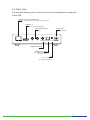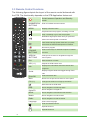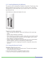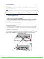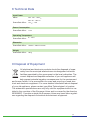
1
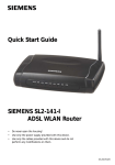
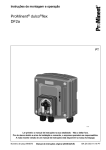
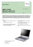
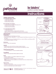
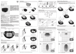
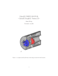
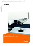
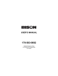
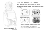
SceneGate Micro
User Manual
2
Content
1
1.1 1.2 1.3 Introduction...................................................................................... 4
Scope............................................................................................... 4
Features........................................................................................... 4
What is High-Definition Television (HDTV)....................................... 5
2
Package Content.............................................................................. 5
3
3.1 3.2
3.3 3.3.1 3.3.2 Getting familiar with your STB.......................................................... 6
Front View........................................................................................ 6
Rear View......................................................................................... 8
Remote Control Functions............................................................... 8
Inserting/Replacing the Batteries..................................................... 9
Using the Remote Control................................................................ 9
4
4.1 4.2 4.3 4.4 4.5 Installation...................................................................................... 10
Picking a good Spot....................................................................... 10
Connecting a High Definition TV-Set via HDMI™...........................11
Connecting an Audio/Video Device (optional)................................ 12
Installation Example....................................................................... 13
Connecting the Power Cord........................................................... 13
5
5.1 Switching on the STB the first time................................................ 14
Software Update............................................................................ 14
6
Troubleshooting............................................................................. 15
7
Abbreviations................................................................................. 16
8
Technical Data................................................................................ 17
9
Disposal of Equipment................................................................... 17
3
1 Introduction
1.1 Scope
The document provides step-by-step instructions of how to install and operate the Set-top Box (STB) and additional technical information. This document
is provided by Albis Technologies.
Note:
Before connecting the external power supply for the first time to the STB,
make sure the STB has been connected properly. For this purpose follow
this user manual carefully step by step.
The STB may run a software update when powered for the first time. Please
be patient and do not unplug the external power supply until the software
update is finished!
The network specific configuration data with the Graphical User Interface
(GUI) depends on the IPTV Supplier and is not part of this manual. It has to
be provided by the IPTV supplier in addition to the information in this manual. Please follow the instructions in this manual carefully. Do not throw this
manual away, keep it near your STB and check if something is not working
properly. Damages as a result of incorrect handling lead to loss of warranty.
1.2 Features
The STB supports:
• High Definition Television (HDTV) with resolution up to 1080p
• H.264 - the new bandwidth optimized Video Codec for improved picture
quality
• Digital Television over IP
• Video on Demand
• High-speed Internet surfing over the TV, Web mail and Simple Gaming
(depending on your Service Provider)
To be able to use all these features you will require a subscription with a
Network Operator or Service Provider.
4
1.3 What is High-Definition Television (HDTV)
What is HDTV and how does it differ from today‘s analog TV? To learn more,
here comes some helpful information.
Analog TV ist the type of TV broadcast you may be most familiar with. A
standard analog TV can display an image at a resolution of 480i (NTSC) or
576i (PAL).
Digital TV is a new system for broadcasting TV signals delivering higher quality for audio and video. Digital TV requires a television set that can receive
and display digital images at resolutions of 1080p, 1080i, 720p, 576i, 480p
or 480i.
HDTV stands for “High Definition Television” and provides best-ever picture
quality. In 16:9 widescreen format, with Dolby Digital surround sound and
picture resolution almost five times that of analog TV, HDTV gives viewers a
cinema experience at home.
2 Package Content
Unpack the product with caution; inspect the items closely to make sure no
item is missing or damaged.
• Set-Top Box
• External mains power supply
• User Manual
• Product Safety, Copyright Notice, License Notice
• Infrared remote control & batteries
Optional content:
• Ethernet cable
• Combined video (CVBS) and audio (L/R) cable
• S/PDIF optical cable
• HDMI™ cable
• External infrared receiver
If you find any item damaged or missing, contact your local distributor
immediately. Keep the box and packing material for future use.
5
3 Getting familiar with your STB
3.1 Front view
On the STB‘s front side you find the Infrared Receiver, the Operation Mode
Indicator and an USB-Interface.
Operation Mode
Indicator
IR Receiver
Operation Mode Indicator
The meaning of the Operation Mode Indicator is as follows:
Operation Mode
Illumination of Standby Button
STB switched off
OFF
STB in standby
red
STB switched on (startup and operation)
Key pressed on Remote Control
green
green flashing
During Software Update
green
Software Update successful
green
Software Upadate failed
red fast blinking
Note:
Do not unplug the external power plug during a software update! This could
damage your STB
Standby Mode
Standby Button on
the Remote Control
6
You can set the STB to standby by pressing the standby
button on the Remote Control.
The STB can be switched on by pressing the standby button
on the Remote Control again. After switching on the STB is
ready to use within a few seconds.
3.2 Rear View
The rear side allows you to connect all your home entertainment equipment
to the STB.
Network Connector 10/100Base-T
(connect a lead from here to your network connection socket)
HDMITM 1.3
(output connector for High Definition)
Analog Audio Output
Power Jack
(right / left)
LAN
HDMI
R
L
(for the power lead)
CVBS S/PDIF IR DC12V
CVBS Video Output
Digital Audio Output
(for an optical connection to
your audio receiver)
IR
(for connection of an
external Infrared Receiver)
7
3.3 Remote Control Functions
The following figure depicts the layout of the remote control delivered with
the STB. The functionality depends on the STB Application feature set.
Switch between Operation and Standby
mode
Power
RUBBER MATERIAL COLOR:
Enter a TV/Radio channel number
NUMMERICAL
RED(PO-192-R)
BUTTONS
GREEN(PZ-385-G)
MENU
Display
YELLOW(PZ-351-Y)
or Exit the menu
Play/Pause
BLUE(PZ-391-B)
BLACK
the live program, recording or movie
Stop a recording or go to the live program
PANTONE COOL
GRAYat
8Chigh
Rewinds
speed. Each time you press this
button the rewind speed is increased
Printing color:WHITE
Fast forward at high speed. Each time you press
this button the fast forward speed is increased
Records a program
COLOUR
BUTTONS
Select colour keys for interactive inputs or Teletext
ARROW
BUTTONS
Changes the channel or navigates through the
Exit
Exits the Menu or Guide
VOL (+/-)
Adjusts the STB volume level
Info
Displays the information about the channel and
services
menu options
programs
UPPER CASE /LOWER CASE/BATTERY DOOR
Material color:BLACK
Display Program Guide
Guide
Printing color: WHITE
and toggle through Favo-
rites
ECEL JU090601
Enter/OK
Select the active item
Back
Returns to the previous channel or menu option
CH (+/-)
Changes the Channel or Page up and down
Mute/Unmute the STB audio
Help
Quick navigation to STB help page
DigitalTV
Quick navigation to Digital TV
Movie
Quick navigation to demand movie selection
Media
Quick navigation to web browser
Radio
Quick navigation to radio channels
Language
Select video language
Enter the Teletext service
Special function 1
Special function 2
8
3.3.1 Inserting/Replacing the Batteries
The remote control is powered by 2 batteries (Type AAA). The life time of the
batteries depends on how often you use your remote control. The battery
compartment is on the bottom side of your remote control. Lift off the cover
by pushing the clip.
Insert batteries as shown and replace the cover.
Precautions for battery replacement:
• When inserting new batteries, make sure that they are the correct way
round.
• Remove empty batteries immediately.
• When disposing used batteries, please comply with governmental regulations or environmental public institution’s rules that apply in your country.
• Never attempt to recharge the batteries.
• Always replace both batteries at the same time. Do not use old and newbatteries together, and do not use batteries of different types.
• If the remote control is not going to be used for a long time, remove the
batteries.
3.3.2 Using the Remote Control
Navigating through the main menu:
1.Press the ‘Menu’ button on the remote control. The main menu appears
on the left side of the TV-Screen.
2.Use the ‘Arrow’ buttons to navigate through the menu.
3.Press the ‘OK’ button to activate the selected function.
9
4 Installation
This chapter describes the installation of the STB and connection to your
Audio/Video equipment.
Note:
Do not connect the external power supply to the STB until you have finished
the installation procedure.
4.1 Picking a good Spot
Stability
• Place your STB on a firm, flat surface.
• Keep away from domestic heating equipment and avoid direct sunlight.
• Allow about 10 cm of free space all around the STB for adequate
ventilation.
• Do not cover the ventilation holes.
Prolonging the lifespan
• Avoid storing or operating the STB in abnormal conditions. High temperatures or excessive humidity could cause the unit to malfunction and
shorten its useful lifespan.
To avoid reflections and irritations of the infrared receiver of the STB, make
sure to place the STB close to the edge of the shelf as depicted below.
10
4.2 Connecting a High Definition TV-Set via HDMITM
If you have a high-definition TV-Set (HDTV), use only the following HD-video
connection method. The STB supports a video resolution up to 1080p
(1920 x 1080) on HDMI™ output.
Connect the HDMI™ cable to the HDMI™ sockets on your STB and HDTV.
LAN
HDMI
R
L
CVBS S/PDIF IR DC12V
Note:
The STB uses HDMI™ autosync mode (default). Hence the output resolution
will automatically be adjusted to the TV resolution.
11
4.2 Connecting an Audio/Video Device (optional)
Usually, the received audio part of the video is played via the audio unit of
your TV-Set. Additionally, it is also possible to connect an external audio device, such as a HiFi or digital surround-sound system to play the audio part.
HDMI
HDTV
Dolby/DTS
S/PDIF
LAN
HDMI
R
L
CVBS S/PDIF IR DC12V
Note:
Before connecting a new device, make sure that your STB power connector
is unplugged.
The STB supports Dolby® Pro Logic down mix on Audio R/L when receiving
Dolby audio streams.
Depending on the system settings for AC3, the STB digital audio output pass
through Dolby® (raw) and converts all other audio formats to PCM. If AC3 is
disabled, all audio formats are converted to PCM. This system setting is also
valid for the HDMI™ interface.
The STB can support various codecs like HE-AAC, AAC, MPEG-1, MP-3,
Dolby® etc. This depends on your Network Operator or Service Provider
respectively.
12
4.3 Installation Example
The following figure shows an example of an installation consisting of the
STB, a HDTV-Set and a Dolby receiver for sound processing:
TV with Remote Control
DT
V
Movie
Media
mo
Pro
Dolby Receiver
HDMI
HDMI
STB with Remote Control
LAN
DT
V
Movie
Media
HDMI
R
L
CVBS S/PDIF IR DC12V
mo
Pro
DSL
Ethernet
Ethernet
WLAN
Notebook
PC
4.4 Connecting the Power Cord
Plug the AC/DC power supply into the wall outlet and connect the power
cable to the STB power jack.
LAN
HDMI
R
L
CVBS S/PDIF IR DC12V
Note:
On the bottom case of the STB is a label which specifies the correct power
supply for your STB.
13
5 Switching on the STB for the first time
After connecting the Power Cord the STB starts to work (no power switch
available). Now switch on your TV-Set. To activate the correct TV input use
the AV button on the TV remote control.
The boot process of the STB is visualized by the Operation Mode Indicator
on the front panel (see chapter 3.1) and with several splash screen information on the TV-Set. After the STB has booted up the TV screen shows the
login screen.
To activate your STB, please follow the instructions on the TV screen.
5.1 Software Update
If a software update over the network is initiated, the boot process will be
longer. Please find more information about the status of a Software Update
in chapter 3.1.
Note:
Do not unplug the external power supply during a software update! This
could damage your STB.
14
6 Troubleshooting
The STB is reliable and easy to use. If you encounter any problem while
using this product, refer to the list below for possible solutions.
Operation Mode Indicator is off
• Make sure the power supply is plugged properly into the wall outlet.
• Make sure the power cable is properly connected to the STB‘s power input.
No image is displayed on the TV screen
• Make sure the power indicator on both devices (TV-Set and STB) is ON.
• Make sure the video cable (CVBS or HDMI) is properly connected.
• Select the correct TV AV channel on your TV-Set.
No sound or low volume
• Check the connections
• Check the STB volume setting by using the STB remote control, check the
audio mute toggle function
• Check the TV volume setting
• Check if the TV supports Dolby Digital decoding. If not change the STB
audio to PCM and disable AC3 in the settings menu respectively.
• Check if the TV supports sound on the selected HDMI interface.
The STB does not react properly to remote control commands
•
•
•
•
•
•
Operate the remote control within a distance of about 7 meters.
Point the Remote Control directly to the STB.
Remove obstacles between the Remote Control and the STB.
Check or replace the batteries of the remote control.
Place the STB close to the edge of the shelf.
Some TV sets (especially Plasma screens) may interfere with the STB as
they also produce infrared radiation. Try to change the location of the STB.
15
7 Abbreviations
DTV DVB DVB-C
DVB-T
DVB-S
GPL GUI LED LGPL OSS PVR
RC RGB S/PDIF SCART STB USB VFD
16
Digital TV
Digital Video Broadcast
Digital Video Broadcast over Cable
Digital Video Broadcast Terrestrial
Digitial Video Broadcast over Satellite
General Public License
Graphical User Interface
Light Emitting Diode
Lesser General Public License
Open Source Software
Personal Video Recorder
Remote Control
Red / Green / Blue
Sony/Philips Digital Interface
Syndicat des Constructeurs d’Appareils Radiorécepteurs
et Téléviseurs
Set Top Box
Universal Serial Bus Interface
Vacuum Fluorescent Display
8 Technical Data
Input Power
Mains
nom. 100 ... 240 VAC
max. 90 ... 264 VAC
SceneGate Micro
12 VDC / 1.0 A
Power Consumption
SceneGate Micro
<7 W
Operating Temperature
SceneGate Micro
0°... 45°C
Dimension
SceneGate Micro
140mm x 100mm x 34mm
Weight
SceneGate Micro
186 g
9 Disposal of Equipment
All electrical and electronic products should be disposed of separately from the municipal waste stream via designated collection
facilities appointed by the government or the local authorities. The
correct disposal and separate collection of your old appliance will
help prevent potential negative consequences for the environment
and human health. It is a precondition for reuse and recycling of used electrical and electronic equipment. For more detailed information about disposal
of your old appliance, please contact your Albis Technologies Ltd. partner.
The statements quoted above are only fully valid for equipment which is installed in the countries of the European Union and is covered by the directive
2002/96/EC. Countries outside the European Union may have other regulations regarding the disposal of electrical and electronic equipment.
17
18
19
Albis Technologies Ltd.
Albisriederstrasse 199
CH-8047 Zürich
Phone+41 58 252 4777
Fax +41 58 252 4778
eMail: www.albistechnologies.com
The information provided in this brochure
contains merely general descriptions or
characteristics of performance which in
case of actual use do not always apply as
described or which may change as a result
of further development of the products.
An obligation to provide the respective
characteristics shall only exist if expressly
agreed in the terms of contract. Availability
and technical specifications are subject to
change without notice.
A1630-X8080-A100-01-7619