1
Specifications
Data Recorder
TR-55
3. How to Read the LCD Display
Device Name
TR-55i
Measurement
Item (*1)
Temperature / Voltage / 4-20mA / Pulse Count
Logging Capacity 16,000 readings
User’s Manual
Recording
Interval
Select from 15 choices: 1, 2, 5, 10, 15, 20, 30 sec. or 1, 2, 5, 10, 15, 20, 30, 60
min.
Thank you for purchasing our product.
Carefully read this instruction manual before using this Unit.
Recording Mode
Endless (Overwrite oldest data when capacity is full) or One Time (Stop
recording when capacity is full)
Communication
Interfaces
Optical Communication (proprietary protocol)
Infrared Communication (IrPHY 1.2 low power)
Power
Lithium Battery: LS14250 (*2) or CR2 (*3) x 1
Battery Life (*4)
See "Estimated Battery Life" in this manual.
Dimensions
H 62 mm x W 47 mm x D 19 mm (excluding protrusions and Input Module)
Weight
About 55 g (including battery / excluding Input Module)
Operating
Environment
-40 to 80 °C
Infrared Port
Waterproof
Capacity (*5)
IP64: Splash proof (rated for use in daily life)
Note: Input Module is not water resistant.
ALM
(Warning LED)
Data Collection
Devices
Communication Port: TR-50U2, TR-50U
Data Collector: TR-57DCi
Outline of TR-55i
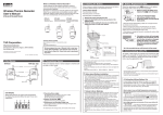
Part Names
External Input Module Type
Splash proof (rated for use in daily life)
TR-55i is a Data Logger designed to measure and record
different items depending on the Input Module to be connected: temperature (Thermocouple/Pt), voltage,
4-20mA, and pulse count. The body is splash proof (rated
for use in daily life), which can be placed in an
environment between -40 and 80°C. Recorded data can
be collected from the TR-55i to PC by using a
Communication Port or Data Collector (sold separately).
The data can then be viewed in graph and table form as
well as printed out by using the supplied software.
Package Contents:
Data Logger (TR-55i), Tubed Lithium Battery (LS14250),
Input Module(*), Strap, User's Manual (this manual
including warranty)
* The Input Module included in the package differs
depending upon which "set model" has been
purchased.
Optical
Communication
Area
Module
Sensor Jack
Data Recorder TR-55i is referred to as the "Unit" in this manual.
*1: See "Input Module User's Manual" for detailed information including measurement range and accuracy for
the Input Module being used.
*2: The included lithium battery (LS14250) is not sold in stores. Please purchase the optional battery set for
low-temperature use (TR-11P2) for replacement.
*3: Only use the CR2 within temperature range of -20 to 60 °C, avoiding exposing the CR2 to excessive vibration such as transportation.
*4: Battery life varies depending upon the ambient temperature in which it is used, the recording interval, the
frequency of communication, and the battery performance. All estimates are based on operations carried
out with a new battery and are in no way a guarantee of actual battery life. When infrared communication
function is enabled, battery life may be shortened if the Unit is used under the inverter type fluorescent
lighting.
*5: This is the waterproof capacity of the logger unit with an input module connected.
The specifications listed above are subject to change without notice.
Distributed by MicroDAQ.com, Ltd.
www.MicroDAQ.com
(603) 746-5524
http://www.tandd.com/
817-1 Shimadachi Matsumoto, Nagano 390-0852 JAPAN
Fax:+81-263-40-3152
© Copyright T&D Corporation. All rights reserved.
This is printed using recycled paper.
Make sure to use the proper size and type of
screwdriver. (Phillips head #1 screwdriver is recommended.)
2. Insert the included battery (LS14250).
Do not remove the battery from its tube casing.
- If using a CR2 lithium battery, the tube is not necessary.
Notes about Battery Installation
- After inserting the battery for the first time, nothing may appear or
occur for about 10 seconds; this is not a malfunction.
- If a new battery has been installed and nothing appears in the display, please remove and reinsert the battery.
- When inserting a battery, make sure no water or foreign objects get
inside the case.
- Make sure that + and - are in the correct direction.
About Lithium Batteries: LS14250 and CR2
3. Check the rubber packing for any cuts
or scratches and close the cover as it
was when opened.
- Dust or defects on the packing can adversely affect the
waterproof capacity; in this case, remove the dust or
replace the packing if it is damaged.
- Be sure to completely close the cover.
- Make sure not to over tighten the screws.
- CR2 lithium batteries sold in stores may also be used, but if you are
using in an environment below -20°C, above 60°C, or in a situation
such as transportation where continued vibration is likely to occur, we
strongly suggest the use of LS14250. (Please purchase the optional
battery set TR-11P2 which includes an LS14250.)
- Please store the LS14250 in a place that is 20°C or less.
- When changing a CR2 battery, we strongly suggest changing the rubber packing and the drying agent. Please purchase the maintenance
set TR-00P1 sold separately.
(Appropriate Tightening Torque: 20N cm to 30N cm{2Kgf cm to 3Kgf cm})
TR-55i-TC (Thermocouple)
Temperature measurement (°F / °C) will be displayed. Sensor type will be displayed under the
measurement; the factory default setting is Type K.
By using the software included with the Communication Port or Data Collector, you can change the
sensor type.
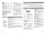
[REC] Mark
The recording status is shown as below.
ON: Recording in progress
BLINKING: Waiting for programmed start
OFF: Recording stopped
[ONETIME] Mark When the recording mode is set to "One Time", this mark
appears. The factory default setting is "Endless" and this
mark will not appear.
Battery Warning Mark When it is time for the battery to be replaced, this mark will appear.
Measurement and Measurements or operational messages are shown
here.
Message Area
The type of sensor connected to or set in the Unit is shown here.
Sensor Type
Thermocouple: Type K, J, T, S
Platinum Thermal Resistance Sensor: Pt (Pt100), PtK (Pt1000)
The infrared communication status is shown as below.
[Ir] Mark
ON: Permitting infrared communication
OFF: Forbidding infrared communication
Unit of
Measurement
TR-55i-Pt (Pt100 / Pt1000)
Temperature measurement (°F / °C) will be displayed. Sensor type will be displayed under the
measurement; the factory default setting is Pt100.
By using the software included with the Communication Port or Data Collector, you can change the
sensor type.
TR-55i-V (Voltage)
Voltage measurement (Unit: V / mV) will be displayed. Due to the wide measurement range, the
Unit has been set by default to adjust the decimal
point automatically to display the measurement in
V. By using the software included with the Communication Port or Data Collector, you can change the
unit of display.
The unit of measurement for the display is shown here.
TR-55i-mA (4-20mA)
1. When it is time for the battery to be replaced, a battery
4-20mA measurement (Unit: mA) will be displayed.
warning mark will appear.
Please change the battery as soon as possible
if this mark appears.
[bAtt] appears in the Measurement and Message Area. Once this
appears, please insert the new battery as quickly as possible.
TR-55i-P (Pulse Count)
There are two display methods for the pulse measurement. By using the
software included with the Communication Port or Data Collector, you can
change the method of display.
Pulse Rate (Max: 61439)
The most recent pulse count (Unit: P) for the recording interval period will be displayed. The display
will be refreshed every one-sixtieth of the recording
interval (at minimum of every one second). 31,500
pulse count will be displayed as [31.50KP], in units
of 10 pulse for display.
- Make sure that [bAtt] is displayed before changing
the battery; otherwise the battery warning mark may
remain even after battery replacement.
- If you change the battery at this point, all recorded
data will be saved.
3. If the battery is further left unchanged, the display will
Total Pulse Count
automatically shut off.
The cumulative number of pulses (Unit: P) will be
displayed from 0 to 9999. The displayed count will
be refreshed every one second, and upon exceeding 9999, the count will start over again from 0.
If, at this time, a new battery is placed in the Unit, [CHEC] will appear on the display
after which recording will begin again using the previously set recording conditions.
Note however that all previously recorded data will have been lost.
Estimated Battery Life
Other Marks or Messages on Display
The battery warning mark will appear based upon the calculation of battery use.
This mark may not appear correctly if the same battery is taken out and put in,
therefore do not remove the battery until it can be replaced with a new one. If infrared communication is set to be permitted, battery life will be shortened.
Logging Capacity FULL
When Recording Mode has been set to "One Time" and the
Unit reaches its logging capacity of 16,000 readings, recording will automatically stop and in the LCD the measurement
and the word [FULL] will alternately appear.
When communication frequency is 4 times a month:
Included Battery
(inserted into tube)
Infrared Communication: OFF
Rec Interval = 1 sec. Rec Interval 10 sec.
TR-55i-TC
About 6.5 months About 14 months
TR-55i-Pt
About 10 months About 24 months
TR-55i-V
About 16 months About 16 months
TR-55i-mA
About 16 months About 16 months
TR-55i-P (Input: Open)
About 24 months
TR-55i-P (Input: Short)
About 16 months
Set Model Number
2. Connecting an Input Module
Insert an Input Module into the module jack. Once the Unit recognizes the module, the LCD display will change as
shown below and recording will start. (If you have purchased an TR-55i-P, the Unit has been set by default to start
recording upon installation of the battery.)
* The factory default settings are as follows: Recording Interval at 10 minutes, Recording Start at Immediate Start, Recording Mode at Endless, Infrared Communication at Forbid.
Set Model Number Measurement Items Input Module
Make sure that the module is completely
inserted until you hear a “click” sound.
man_users-tr55i-1-eng.indd
Display varies depending upon the model being used.
2. After removing the battery, wait for about three seconds until
1. Remove the screws and open the cover.
Rubber
Packing
Example of Display
2012.04 16504750003 (1st Edition)
1. Installing the Battery
Cover
Basic LCD
Display
Battery Replacement
T&D Corporation
Screws
When being used in very hot or cold environments the display may become difficult to read. This is not a malfunction.
1
LCD Display Items (detailed in "How to Read the LCD Display" section)
TR-55i-TC
Temperature
(Type K, J, T, S)
Thermocouple Module
(TCM-3010)
Measurement, Unit of Measurement, Sensor Type, Operational Status
TR-55i-Pt
Temperature
(Pt100, Pt1000)
PT Module (PTM-3010)
Measurement, Unit of Measurement, Sensor Type, Operational Status
TR-55i-V
Voltage
Voltage Module (VIM-3010)
Measurement, Unit of Measurement, Operational Status
TR-55i-mA
4-20mA
4-20mA Module (AIM-3010)
Measurement, Unit of Measurement, Operational Status
TR-55i-P
Pulse Count
Pulse Input Cable (PIC-3150)
Measurement, Unit of Measurement, Operational Status
Infrared Communication: ON
Rec Interval = 1 sec. Rec Interval 10 sec.
About 5.5 months About 10 months
About 7.5 months About 14 months
About 11 months About 11 months
About 11 months About 11 months
About 18 months
About 11 months
- When the recording method is set to "average value" for the TR-55i-V or TR-55i-mA, the battery life will be the same as when the recording interval is one second regardless of the actual
recording interval.
- The battery warning mark may appear sooner than noted above.
- Battery life will be shortened when: downloading data very often, setting the recording interval at less than ten seconds, or measuring in an environment below -20°C or above 60°C.
Notes about Changing the Battery
- Before replacing a battery, please make sure to download any necessary data and
proceed with changing the battery.
- If + (plus) and – (minus) are mistaken, or if the battery terminals + and – are shorted,
the recorded data that is stored in the Unit will be lost.
- Downloading of data cannot occur while the battery is removed.
Estimation of time until [FULL] is displayed
Recording Interval 1 second
Period
30 seconds
1 minute
10 minutes
About 4 hours About 5 days About 11 days About 111 days
60 minutes
About 1 year and
10 months
Check
If this appears, all data that was stored in the Unit will
have been erased. This message will appear under the
following conditions:
- The first time a battery was inserted after purchase
- When the battery is replaced after having been taken out for
a long period
- If the battery is replaced after the battery power has been
lost.
Continued on Back Page.
2012/04/11
13:58:57
3. How to Read the LCD Display (continued from previous page)
Input Module Unrecognized (factory default)
Warning (Set Limit Exceeded)
This will appear if, after purchasing, the Input Module
has never been connected to the Unit. (Unit of Measurement not displayed)
Using the software that comes with the Communication Port or Data Collector, you can make settings for
the Upper / Lower Limits and Warning Judgement
Time. If a measurement exceeds one of the set limits,
the warning LED and a message will be displayed.
Note that a TR-55i-P has been set to measure pulse count by
default, therefore the unit "P" will be displayed.
Input Module Unconnected or Damaged
Warning LED (flashing)
Upper Limit Exceeded
This will appear if the Unit cannot confirm a connection with
the Input Module after having recognized it. (Unit of Measurement displayed)
If nothing is displayed after reconnecting the sensor to the Unit, there
is a possibility that the sensor or the Unit has been damaged.
This will be displayed when a sensor has not been
connected to the module or the wire has been broken.
Recording is in progress and so is battery consumption.
If nothing appears on display after reconnecting the sensor to
the Unit, there is a possibility that the sensor or the Unit has
been damaged.
Measurement Range Exceeded
[OL] will appear if a measurement exceeds the measurement range.
-
All rights of this User’s Manual belong to T&D Corporation. It is prohibited to use, duplicate and/or arrange a part or whole of the manual without the permission of T&D Corporation.
All registered trademarks, company names, product names and logos mentioned herein or for products being used are the property of T&D Corporation or of their respective owners.
Specifications, design and other contents outlined in the manual are subject to change without notice due to continual improvements.
Please follow the safety precautions outlined in the manual carefully. We cannot guarantee nor are we responsible for safety if this product is used in any manner other than was intended.
On-screen messages in this manual may vary slightly from the actual messages.
Please notify the distributor from which you purchased this product or T&D Corporation of any mistakes, errors or unclear explanations in this manual. T&D Corporation accepts no responsibility for any damage or loss
of income caused by the use of our product.
This product has been designed for private or industrial use only. It is not for use in situations where strict safety precautions are necessary such as in connection with medical equipment, whether directly or indirectly.
We are not responsible for any malfunction or trouble caused by the use of our product or for any problem caused by the use of measurement results of our product. Please be fully aware of this before using our product.
This User’s Manual cannot be reissued, so please keep it in a safe place.
Please read the warranty and provisions for free repair carefully.
Safety Precautions and Instructions
Lower Limit Exceeded
The following items should be strictly obeyed for the safe usage of this product, and for protecting yourself and other people from bodily harm and/or damage to property.
To ensure the proper use of this product, we ask that before using it you carefully read, understand and follow the safety rules and precautions as outlined below.
Starting the Warning Monitoring Function
If these settings are made in an environment where one of the limits is being exceeded
and recording is started, the monitoring function will enter “wait” mode. Once a measurement returns to within the set limits, the monitoring function will begin to operate.
How to Turn Off a Warning
-
-
If a measurement exceeds the set upper limit, the measurement and [HI] will alternately appear on the LCD screen.
If a measurement exceeds the set lower limit, the measurement and [Lo] will alternately appear on the LCD screen.
Sensor Unconnected or Damaged
Notices about this User’s Manual
In order to properly use this product, please carefully read this manual before using.
T&D Corporation accepts no responsibility for any malfunction of and/or trouble with this product or with your computer that is caused by the improper handling of this product
and will deem such trouble or malfunction as falling outside the conditions for free repair outlined in the attached warranty.
Restart recording from the software.
In the software use [Clear Warning] (only with TR-50U2 and TR-50U)
Download the recorded data (only when successfully completed).
Produce a condition so that [CHEC] is displayed.
DANGER
Do not disassemble, repair or modify the Unit.
It may result in malfunction or unexpected accidents.
Do not use any other batteries than those that are specified in this manual.
It may cause fire or malfunction.
If water or a foreign object enters the case, immediately remove the battery
and cease using it.
It may result in malfunction or unexpected accidents.
Store the Unit and accessories out of the reach of children.
Not doing so may cause an unexpected accident.
If any smoke or strange smells are emitted from the Unit, immediately remove
the battery and stop using.
Continued use may cause fire or electrocution.
Please be careful not to touch the Unit during or after use in overly hot or cold
environments.
It may cause burns or frostbite.
Display Range Exceeded
CAUTION
The measurement in the LCD display will flash if it
exceeds the display range of the Unit.
Distributed by MicroDAQ.com, Ltd.
www.MicroDAQ.com
(603) 746-5524
4. Communicating with your Computer
In order to change settings in the Unit such as recording settings, download recorded data from the Unit to your computer, or
communicate with your computer, it is necessary to purchase separately a Communication Port (TR-50U2/50U) or Data Collector
(TR-57DCi).
By using the software "T&D Recorder for Windows (TR-5,7xU)" supplied with the Communication Port or Data Collector, it is
possible to carry out communication with a PC. For details about how to make recording settings, download data and other
operations, please see the User’s Manual that comes with the Communication Port or Data Collector.
The latest version of "T&D Recorder for Windows (TR-5,7xU)" can be downloaded free of charge from our website. (TR-55i can
be used with Ver. 2.00 or higher.)
How to Communicate with the Computer
Using a PC allows the following:
1. Follow directions as issued in the software to connect
It is possible to change recording settings in the Unit, download recorded data to a PC, and view downloaded data.
the Communication Port or Data Collector to your PC.
Communication Cable
2. Place the Data Logger on the Communication Port or
Data Collector making sure to align the optical communication areas and slitted areas.
TR-55i
Data Collector TR-57DCi
Optical
Communication
Area
Communication Port
TR-50U2, TR-50U
Slitted Area
This device complies with Part 15 of the Federal Communications Commission (FCC)
rules. Operation is subject to the following two conditions: (1)This device may not
cause harmful interference, and (2)this device must accept any interference received,
including interference that may cause undesired operation.
FCC Statement
This equipment has been tested and found to comply with the limits for a Class B
digital device, pursuant to Part 15 of the FCC Rules. These limits are designed to
provide reasonable protection against harmful interference in a residential installation.
This equipment generates, uses and can radiate radio frequency energy and, if not
installed and used in accordance with the instructions, may cause harmful interference
to radio communications. However, there is no guarantee that interference will not
occur in a particular installation. If this equipment does cause harmful interference to
radio or television reception, which can be determined by turning the equipment off
and on, the user is encouraged to try to correct the interference by one or more of the
following measures:
- Reorient or relocate the receiving antenna.
- Increase the separation between the equipment and receiver.
- Connect the equipment into an outlet on a circuit different from that to which the receiver is connected.
- Consult the dealer or an experienced radio/TV technician for help.
To comply with the limits for the Class B digital device, pursuant to Part 15 of the FCC
Rules, this device must be installed in computer equipment certified to comply with the
Class B limits.
All cables used to connect the computer and peripherals must be shielded and
grounded. Operation with non-certified computers or non-shielded cables may result
in interference to radio or television reception.
Caution:
Changes or modifications not expressly approved by the party responsible for compliance could void the
user’s authority to operate the equipment.
This may lead to data loss.
The Unit becomes splash proof (rated for use in daily life) only after the Input
Module has been connected.
Without the module connected, neither the module jack nor the connector part of the temperature
sensor on the Unit is water resistant; make sure not to get wet.
If the Unit is not to be used for a long period of time, store it in a place where
it is not exposed to high temperature and high humidity.
If the Unit has condensation on the inside, it may cause malfunction and damage.
Do not remove or reinsert the battery once it has been set; continue using
until battery power is depleted. Always use a new battery for replacement.
Not doing so may result in improper operation.
To maintain waterproof capacity, we suggest periodically changing the parts
inside the case.
Data Recorder TR-55i Warranty
Guarantee Period
Customer's name
If the rubber packing should be damaged or deteriorated, please replace it along with the drying agent.
If the Unit is subjected to significant temperature change while wet, it may
cause condensation inside the case.
Address
The factory default settings are as follows: Recording Interval at 10 minutes, Recording Start at Immediate Start, Recording Mode at Endless,
Infrared Communication at Forbid.
Do not drop or expose the Unit to a strong impact.
Phone No.
It may cause damage or malfunction.
Distributor's name
Select from 15 choices:
Recording
1, 2, 5, 10, 15, 20, and 30 seconds or 1, 2, 5, 10, 15, 20, 30, and 60 minutes
Interval
Recording Start Immediate Start: Recording will start immediately upon installation of the battery.
Do not use or store the Unit in places such as listed below. It may result in
malfunction or unexpected accidents.
Programmed Start: Recording will start at the set date and time.
One Time: Upon reaching logging capacity of 16,000 readings, recording will
Recording
automatically stop. (The word [FULL] and the measurement will
Mode
alternately appear on the LCD screen.)
Endless: Upon reaching capacity of 16,000 readings, the oldest data will be
overwritten and recording will continue.
Permit: Infrared Communication will be possible.
Infrared
Communication Forbid: Infrared Communication will not be possible.
Function
Notes about Optical Communication
- Proper communication may not be possible in the following situations:
where temperatures are very high or very low, in an environment with intense brightness (higher than 5,000lx), or when the remaining battery life for the Unit is very low.
1 year from date of purchase
Date of Purchase
Especially be careful with temperature changes from high to low; if the Unit has condensation on
the inside, it may cause malfunction, damage, and/or unexpected accidents.
Notes about Communication Devices
2
Harmful gases or chemicals may cause corrosion and/or other danger to the
Unit. Also, by coming in contact with hazardous substances, harm may occur
to the people handling the Unit. Therefore, do not use or store the Unit in any
environment that is exposed to chemicals and harmful gases.
Battery life varies depending upon measuring environment, frequency of
communication, Unit settings, and battery performance.
When using the Unit in unusually high or low temperature environments, the
battery power will be depleted more quickly than when using under normal
temperature conditions.
Battery terminals may provide insufficient contact due to age or vibration.
Radio, EMC and Safety Regulations
Recording Settings for the Unit
- When using a Data Collector, you can download recorded data, view the data in
graph form, and make all necessary recording settings without connecting to a PC.
man_users-tr55i-1-eng.indd
This Unit has been designed for private and/or industrial use only. It is not for
use in situations where strict precautions are necessary such as in connection with medical equipment, where directly or indirectly.
Compliance Information
Do not put fingers or foreign objects into the modular jack.
- Areas exposed to direct sunlight
- Areas exposed in water or high-pressure water flow
- Areas exposed to organic solvents and corrosive gas
- Areas exposed to strong magnetic fields
- Areas exposed to static electricity
- Areas near fire or exposed to excessive heat
- Areas exposed to excessive dust, dirt and smoke
Contact with oil may cause cracks to appear in the casing of the Unit. When using
this Unit in environments where such oils are present, please insure that it is
protected from contact through use of a polyethylene bag or other means.
Notices about Infrared Communication
Do not place the unit in areas exposed to direct sunlight or incandescent light, or
near other infrared devices. It may cause communication to not work properly.
Proper communication may not be possible if the infrared port becomes covered
with dirt and/or dust. If it gets dirty, wipe it with a soft cloth.
Do not touch the infrared port with your finger during infrared communication.
Notices about using the Input Modules
When using T&D Recorder for Windows to make "Adjustment Settings", the
adjustment values will be saved to the Input Module. Therefore, when an Input
Module is replaced, it is necessary to re-make any desired adjustment settings to be
written into the newly connected module.
Address
Phone No.
Object of Repair
Method of Repair
Main Unit (excluding Input Modules and any other options.)
Send in for Repair
Provisions for Free Repair
1. If the unit does not work properly despite the fact that the customer used it properly and in line with
the manual, the unit shall be repaired free of charge through the distributor which sold the unit.
2. If the customer requests free repair because of trouble within the warranty period, bring or send the
unit along with the warranty to the distributor.
3. If you have moved after purchasing, or there are difficulties contacting the distributor from which you
purchased the unit, please contact T&D directly for service.
4. Free repair is not available in the following cases even though it is within the warranty period:
1. Trouble or damage was caused by careless operation, natural disaster, fire, public pollution, or use
of a power source other than specified.
2. If repair, adjustment, disassembly or modification of the unit has been carried out by a person other
than a T&D authorized engineer.
3. Trouble or damage was caused by transportation, movement or dropping of the unit after purchase.
4. Failure to submit the warranty or failure to fill in all items required in the warranty.
5. The warranty cannot be reissued.
This warranty only promises customers free repair within the period and conditions clarified in this
warranty. Therefore, the customer's legal rights will not be limited by this warranty. For further information on repair and other service questions after the termination of the warranty period, contact your
distributor.
2012/04/11
13:58:58