1
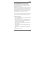
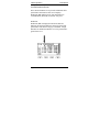
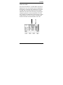
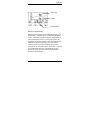
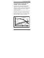
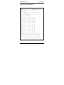
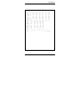
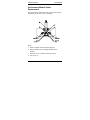
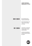
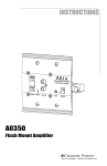
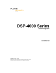
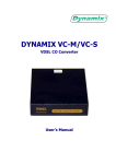
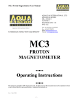
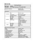
LANcat™ System 6
with C5e
Performance Module
User Manual
Addendum
Datacom Textron may make improvements or additions to this
publication or their products at any time without notice.
Datacom Textron shall not be liable for technical or editorial
errors or omissions contained herein.
LANcat is a registered trademark of Datacom Textron.
P/N 13789 Rev. B
© Copyright 1998 by Datacom Textron
11001 31st Place West
Everett, WA 98204
Telephone
425-355-0590
800-468-5557
Fax
425-290-1600
www.datacom.textron.com
Contents
Contents
LANcat System 6 Introduction
3
Enhanced Test Specifications....................................... 4
Test Reports ................................................................ 5
Performance Module Installation
6
Autotests
8
Running Autotest ........................................................ 10
Viewing 250 MHz Autotest Results ........................... 11
Viewing Test Results ................................................ 11
Link Performance Screen .......................................... 12
Power Sum ACR ....................................................... 13
Return Loss ............................................................... 14
Viewing Return Loss Results .................................... 14
ELFEXT.................................................................... 16
Viewing Power Sum ELFEXT Results ..................... 18
Certifying Category 5 Cabling
20
Pair-to-Pair NEXT Method ....................................... 20
Power Sum NEXT Method ....................................... 21
Page 1
LANcat System 6
User Manual
Link Performance Analysis Beyond
100 MHz – ACR and Headroom
23
Test Reports
24
Performance Module Cable Replacement 28
Warranty
31
User-Guard™ Support Program............................... 31
Two Year Product Warranty ..................................... 32
Page 2
Introduction
LANcat System 6 Introduction
LANcat System 6 consists of a pair of LANcat testers
equipped with 250 MHz C5e Performance Modules. The
C5e Performance Modules take Category 5 testing
beyond current Category 5 standards of 100 MHz,
providing critical information for Enhanced Category 5
and Gigabit cabling. System 6 offers an unequalled
combination of power, measurement precision, ease of
use, and low ownership cost. This unique modular design
makes LANcat the most versatile tester on the market.
In addition to being fully compliant with TIA TSB 67
requirements for certifying CAT 5/Class D links, the
LANcat System 6 performs several important new
measurements including Power Sum Near End Crosstalk
(PS-NEXT) and Power Sum Attenuation-to-Crosstalk
Ratio (PS-ACR) to 250 MHz. Modules provide Equal
Level Far End Crosstalk (ELFEXT), PS ELFEXT, and
Return Loss testing as required in the proposed
Enhanced Category 5 standard, to 100 MHz.
Padded protective overcases supplied with the system
enclose both the tester and performance module,
providing protection from damage in the field while
allowing full access to the display and all controls.
The LANcat System 6 with C5e Performance Modules
fully complies with the proposed TIA Level IIe accuracy
specifications.
Page 3
LANcat System 6
User Manual
This manual only describes features and operation
specific to LANcat Handsets equipped with C5e
Performance Modules. Please refer to the LANcat
Series Cable Testers User Manual for general
operation, maintenance, and specifications.
Enhanced Test Specifications
The following 100 MHz Certification Standards can be
extended to 250 MHz for verification purposes.
•
TSB-67 CAT 3, 4, 5
•
TIA Category 5e
•
TSB-95
•
ISO 11801 Class C, D
•
EN50173 Class D
•
ScTP Class C, D
•
AS/NZS 3080 Class C, D
•
BICC Millennium
•
FTP 120 Ohms
•
JIS X 5150
Page 4
Introduction
A TwoWay system (two LANcat System 6 testers) is
required for 250 MHz tests and all Remote NEXT,
ELFEXT, and Return Loss tests. Firmware versions
below 6.00 require factory calibration before running
250 MHz tests. Contact Datacom Textron for factory
calibration details.
Cable Grading is not available for firmware versions
6.00 D3/D4 or higher. Cable grading has been
superceded by headroom and link performance analysis
detail screens.
The following 100 MHz Network Standards can be
extended to 250 MHz for verification purposes.
• IEEE 100BASE-Tx
• ANSI X3T9.5 TP-PMD
• ATM 155 MBPS
Test Reports
Each LANcat tester can store up to 400 test reports (800
total per system).
Test reports can be saved in 3 different formats:
•
•
•
Encrypted tamper proof Report Manager format.
Comma Separated Variable for import into
spreadsheet programs.
Text files for import into word processing
programs.
Page 5
LANcat System 6
User Manual
Performance Module Installation
Make sure the unit is turned off before attempting
module installation or removal.
To install the C5e Performance Module, slide it into the
opening on the LANcat until the screws rest against the
retainers, then evenly hand-tighten the screws until the
module is properly seated (refer to Figure 1-1). To
remove a module, loosen the thumbscrews at either side
of the module until the screws are free of the retainers.
Hold the module on either side and slide it out of the
opening.
CAUTION
To avoid damage to the LANcat, tighten the
screws evenly using finger pressure only.
Make sure to turn both screws either
simultaneously or alternately in small
increments. The module is designed to be
installed or removed without tools.
Page 6
Performance Module Installation
STATIC AWARENESS
The LANcat contains static sensitive electronics inside
the main body. Use appropriate precautions when
removing and installing performance modules.
Figure 1-1. Module Installation
Page 7
LANcat System 6
User Manual
Autotests
Autotest is a preprogrammed suite of tests that are
required to certify a cabling link. The following tests
are required by TIA/EIA:
•
•
•
•
•
•
Wire Map
Near-End Crosstalk (NEXT)
Attenuation
Length
Return Loss (CAT5e)
ELFEXT (CAT5e)
The following tests may be added to the Autotest suite of
tests by defining a Custom Cable standard (see the
LANcat User Manual, Appendix A, Defining Custom
Standards):
•
•
•
•
•
•
•
•
•
•
Page 8
Delay / Delay Skew
250 MHz UTP (100 MHz standards only)
Power Sum Link Performance
Power Sum NEXT
Power Sum ACR
Resistance
ACR
Return Loss
ELFEXT
Power Sum ELFEXT
Autotests
Please note that impedance is not tested when using the
C5e Performance Module. The maximum cable length
measured by the System 6 is 1100 feet.
NOTES ON 250 MHZ TESTING
• 250 MHz testing is available for all 100
MHz tests. This option is available by
entering the CHANGE CABLE
STANDARD menu and editing the
selected test standard. Using this option,
the instrument will extend NEXT and
ATTENUATION measurements out to
250 MHz.
• PASS or FAIL indications when
running Autotest are based on existing
100 MHz test standards.
• 250 MHz tests can also be enabled by
selecting “250 MHz UTP” in the Cable
Standard menu.
• If the LANcat fails any test, it will stop
and display the failure. You may
continue testing by pressing the
CONTINUE (F4) softkey.
Page 9
LANcat System 6
User Manual
Running Autotest
1.
2.
3.
4.
Connect each tester to the cable under test.
Set one tester dial to REMOTE.
Set the other tester dial to AUTOTEST.
Use the up/down arrow keys to enter the CHANGE
CABLE STANDARD menu.
5. Use the up/down arrow keys to highlight the desired
Cable Standard. Press SELECT (F4) to update both
testers to the chosen standard. The test will run
automatically.
6. After completing an Autotest, press START (Fl) to
re-start Autotest. Press VIEW (F3) to review the test
results. Press SAVE (F4) or ENTER to save the test
results.
Page 10
Autotests
Viewing 250 MHz Autotest Results
After performing an Autotest, LANcat will display
PASS, FAIL or PASS*, FAIL*. LANcat also displays
Headroom and Crossover.
Headroom (expressed in Decibels or dB) is based on the
worst case measurement of Power Sum NEXT relative to
the NEXT standard for the cable test chosen. Crossover
value (in MHz) is the frequency at which Power Sum
ACR equals zero (PSNEXT-Attenuation = PSACR)
Two new System 6 test summary screens are shown after
an Autotest: Link Performance and Power Sum ACR.
Viewing Test Results
1. After completing Autotest, press VIEW (F3) from the
Autotest results screen.
2. Press the arrow keys to view additional summary test
result screens (Link Performance and PSACR are
shown after the NEXT results).
3. Press SAVE (F4) or ENTER at any time to save the
Autotest results.
4. Press GRAPH (F2) to view a graphic display of the
test results.
5. Press SEND (F1) to send the results to the Remote
Unit.
6. Press ESC to exit View.
Page 11
LANcat System 6
User Manual
Link Performance Screen
The Link Performance screen provides additional cable
performance information. This screen displays
Headroom (HR) and the Power Sum Attenuation to
Crosstalk Ratio (PS-ACR) for all four wire pairs.
Headroom
Headroom (HR) is displayed in Decibels (dB) and
indicates the measured difference between actual cable
performance and current Category 5 standards. A high
dB value for Headroom indicates a level of performance
greater than Cat 5.
Page 12
Autotests
Power Sum ACR
Power Sum Attenuation to Crosstalk Ratio (PS-ACR) is
displayed two ways. The column ACR=10 dB indicates
the frequency at which the pair tested had an ACR value
of 10 dB. This is generally accepted to be the useable
bandwidth of the cable while still having enough signal
strength to guarantee low data transmission error rates.
The column ACR=0 dB indicates the frequency at which
ACR measured zero. This zero point is considered the
absolute maximum useable bandwidth of the cable.
Page 13
LANcat System 6
User Manual
Return Loss
Return Loss is a measure of the reflected energy caused
by impedance mismatches in the cabling system. Return
Loss is expressed as the ratio, in dB, of the incident
power and reflected power. Since it is desirable to have
the least amount of energy reflected, larger values are
desirable. Return Loss is especially important for
applications such as Gigabit Ethernet that use
simultaneous bi-directional transmission. Return Loss
measurements are made to 100 MHz as required in the
proposed Enhanced Category 5 specification.
Viewing Return Loss Results
Test
Specification
Press GRAPH (F2) to view a graph of Return Loss
results.
Page 14
Autotests
Test Limit
Cursor
Test Results
Return Loss Reporting
Return Loss measurements for Enhanced Category 5 are
being added to TIA/EIA 568-A via Standards Proposal
4195-A. When this proposal is adopted, standard 568-A
will be amended as 568-A-5. At this point in time, the
committee developing Proposal 4195 is still debating the
standards for devices measuring return loss and the
return loss limits for installed cabling. Since actual
requirements are still under debate, return loss is reported
for informational value only. Standards that require
return loss measurements will not be failed based on
return loss measurements.
Page 15
LANcat System 6
User Manual
ELFEXT
Equal Level Far End Crosstalk or ELFEXT is derived
from Far End Crosstalk (FEXT) measurements and
attenuation measurements. FEXT is a measure of the
unwanted signal from a transmitter at the near-end into a
neighboring pair at the far-end. ELFEXT is expressed in
dB as the difference between the measured FEXT and
the attenuation of the disturbed pair. Power Sum
ELFEXT takes into account the combined crosstalk on a
receive pair from all the far end disturbers operating
simultaneously. ELFEXT measurements are made to 100
MHz as required in the proposed Enhanced Category 5
specification.
Viewing ELFEXT Results
Test Summary
Press DETAIL (F3) to view ELFEXT test specifications.
Page 16
Autotests
Test
Specification
Press GRAPH (F2) to view a graph of ELFEXT Results
Test Limit
Cursor
Test Results
Page 17
LANcat System 6
User Manual
Viewing Power Sum ELFEXT Results
Test Summary
Press SPEC (F3) to view PS ELFEXT test specifications.
Test
Specification
Press GRAPH (F2) to view a graph of PS ELFEXT
Results.
Page 18
Autotests
Test Limit
Cursor
Test Results
Page 19
LANcat System 6
User Manual
Certifying Category 5 Cabling
Pair-to-Pair NEXT Method
NEXT, as defined in TIA TSB-67, is a measure of signal
coupling from one pair to another pair within the fourpair cable. It is also sometimes called pair-to-pair NEXT.
TSB-67 requires that pair-to-pair NEXT be measured on
all six pair combinations, and that the worst pair-to-pair
NEXT measurement not exceed specified test limits for
the Basic Link or Channel test configurations.
The pair-to-pair NEXT measurements, however, only
account for crosstalk coupled from any one pair to
another - not the possible total crosstalk that might be
coupled from multiple pairs in the same sheath. The
TSB-67 methodology assumes that only two pairs of the
cable would be used at any given time for data
transmission. While pair-to-pair NEXT is an appropriate
crosstalk measure for 2-pair network schemes, such as
10BASE-T and 100BASE-Tx, it does not provide an
adequate measure of cable performance when multiple
pairs within the same sheath may be transmitting
simultaneously, such as in Gigabit Ethernet.
Page 20
Certifying Category 5 Cabling
Power Sum NEXT Method
Power Sum NEXT (PS-NEXT) is the sum of the NEXT
power coupled to a wire pair from all other adjacent
pairs. Power Sum is specified by TIA 568A as the
recommended method for characterizing NEXT of
multipair backbone cable. PS-NEXT can be computed
from the individual pair-to-pair NEXT measurements.
The graph below shows the computed PS-NEXT for a
typical CAT 5 link, compared to a composite curve
representing the greatest (i.e. closest to the TSB-67
NEXT limit) pair-to-pair NEXT values for the same link.
As seen from this example, the PS-NEXT values are
always worse than the greatest pair-to-pair NEXT values.
In fact, PS-NEXT for four-pair cabling can be as much
as 4.77 dB worse than the greatest pair-to-pair NEXT
measurement. A link that easily passes TSB-67 Category
5 pair-to-pair NEXT requirements might therefore fail if
PS-NEXT is used as the measure.
Page 21
LANcat System 6
User Manual
Several manufacturers of enhanced-performance CAT 5
cables and connectors specify PS-NEXT as a measure of
product performance. Because PS-NEXT is a more
stringent NEXT characterization method, components
that are specified and tested to meet Power Sum are more
likely to deliver optimum performance, even beyond TIA
568A defined CAT 5 requirements.
Page 22
Link Performance Analysis
Link Performance Analysis Beyond
100 MHz – ACR and Headroom
Power Sum ACR measurements beyond 100 MHz are
valuable for determining adequate performance of
enhanced Cat 5 cabling. Current Cat 5 standards require
a minimum of 10 dB ACR at 100 MHz. Proposed Cat 6
standards recommend an ACR value of a minimum
10 dB ACR at 200 MHz.
System 6 provides this measure of cable performance up
to 250 MHz. The frequency at which the cable had a
measured 10 dB ACR value is clearly displayed in the
LINK PERFORMANCE screen. The following graph
illustrates the ACR vs. Frequency relationship:
Measured
Cable Attenuation
Headroom
Attenuation
Spec
dB
Next Spec
Measured Cable NEXT
Cable Test Frequency (MHz)
100
ACR Crossover
Point
250
Page 23
LANcat System 6
User Manual
Test Reports
Up to 400 test reports can be saved in each LANcat
System 6 tester. Reports can be uploaded to a PC and
viewed or printed with the Report Manager software.
Please refer to Chapter 6 in the LANcat Series Cable
Testers User Manual for more information on working
with reports.
Page 24
Test Reports
Sample 250 MHz UTP Autotest Report
LANcat
CABLE CERTIFICATION REPORT #
Circuit ID:
Cable Test Standard: CAT5EN Basic Link
Location: ___________________________
Date Tested: 11/04/1998
1
Local Module Type: C5e Modular Plug
Remote Module Type: C5e Modular Plug
Serial Number: 1111111 V9.99D4
Cable NVP: 72.0%
TEST SUMMARY: PASS
_______________________________________________________________________________
Wire Map: PASS Near End
1
2
3
6
4
5
7
8
Shield
|
|
|
|
|
|
|
|
open
Remote End
1
2
3
6
4
5
7
8
_______________________________________________________________________________
Length:
PASS
Limit: 308ft
Pair
Length
Delay Skew
Comments
1,2
8ft
1ns
OPEN
3,6
8ft
0ns
OPEN
4,5
8ft
0ns
OPEN
7,8
9ft
2ns
OPEN
______________________________________________________________________________
Attenuation:
PASS
1,2
3,6
4,5
7,8
PASS
PASS
PASS
PASS
Attenuation
dB
1.1
1.0
1.0
0.9
Limit
dB
21.7
21.7
21.5
21.7
Margin
dB
+20.6
+20.7
+20.5
+20.8
Frequency
MHz
101.0
101.0
99.0
101.0
______________________________________________________________________________
PSNEXT:
PASS
1,2
3,6
4,5
7,8
PASS
PASS
PASS
PASS
Power Sum
dB
41.0
39.0
39.6
42.0
Limit
dB
33.3
32.5
32.3
35.9
Margin
dB
+7.7
+6.5
+7.3
+6.1
Frequency
MHz
86.8
97.6
100.1
60.5
Remote PSNEXT: PASS
1,2
3,6
4,5
7,8
PASS
PASS
PASS
PASS
Power Sum
dB
41.1
41.3
39.9
41.8
Limit
dB
33.3
35.0
32.3
35.9
Margin
dB
+7.8
+6.3
+7.6
+5.9
Frequency
MHz
87.0
68.6
100.1
60.5
______________________________________________________________________________
Return Loss:
1,2
3,6
4,5
7,8
Return Loss
dB
19.9
15.5
21.0
15.4
Limit
dB
17.0
12.5
17.0
12.9
Margin
dB
+2.9
+3.0
+4.0
+2.5
Frequency
MHz
0.9
87.3
0.9
76.9
Rem Return Loss:
Return Loss
dB
Limit
dB
Margin
dB
Frequency
MHz
1,2
19.8
17.0
+2.8
0.9
3,6
15.6
12.5
+3.1
86.6
4,5
19.9
17.0
+2.9
0.9
7,8
15.4
12.7
+2.7
81.2
Page 25
LANcat System 6
User Manual
Sample C5e Autotest Report
LANcat
CABLE CERTIFICATION REPORT #
Circuit ID:
Cable Test Standard: CAT5e Basic Link
Location: ___________________________
Date Tested: 12/10/1998
1
Local Module Type: C5e Modular Plug
Remote Module Type: C5e Modular Plug
Serial Number: 0000000 V9.99D4
Cable NVP: 72.0%
TEST SUMMARY: PASS
_______________________________________________________________________________
Wire Map: PASS Near End
1
2
3
6
4
5
7
8
Shield
|
|
|
|
|
|
|
|
open
Remote End
1
2
3
6
4
5
7
8
_______________________________________________________________________________
Length:
PASS
Limit: 308ft
Pair
Length
Delay Skew
Comments
1,2
8ft
1ns
OPEN
3,6
7ft
0ns
OPEN
4,5
8ft
0ns
OPEN
7,8
9ft
2ns
OPEN
_______________________________________________________________________________
Attenuation:
PASS
1,2
3,6
4,5
7,8
PASS
PASS
PASS
PASS
Attenuation
dB
0.9
0.9
0.9
0.9
Limit
dB
21.7
21.7
21.7
21.7
Margin
dB
+20.8
+20.8
+20.8
+20.8
Frequency
MHz
101.0
101.0
101.0
101.0
_______________________________________________________________________________
PSNEXT:
PASS
1,2
3,6
4,5
7,8
PASS
PASS
PASS
PASS
Power Sum
dB
49.5
39.1
39.0
43.4
Limit
dB
41.1
32.4
32.3
35.7
Margin
dB
+8.4
+6.7
+6.7
+7.7
Frequency
MHz
28.9
99.0
100.1
62.1
Remote PSNEXT: PASS
1,2
3,6
4,5
7,8
PASS
PASS
PASS
PASS
Power Sum
dB
40.7
38.8
39.3
43.4
Limit
dB
33.2
32.7
32.3
35.7
Margin
dB
+7.5
+6.1
+7.0
+7.7
Frequency
MHz
88.4
94.9
100.1
62.3
_______________________________________________________________________________
Return Loss:
1,2
3,6
4,5
7,8
Return Loss
dB
16.3
14.8
21.0
15.3
Limit
dB
13.0
12.6
17.0
12.7
Margin
dB
+3.3
+2.2
+4.0
+2.6
Frequency
MHz
73.5
83.9
0.9
82.1
Rem Return Loss:
1,2
3,6
4,5
7,8
Return Loss
dB
16.4
14.3
21.8
16.4
Limit
dB
12.9
12.5
17.0
12.9
Margin
dB
+3.5
+1.8
+4.8
+3.5
Frequency
MHz
76.0
87.7
0.9
76.0
______________________________________________________________________________
ELFEXT: PASS
12/36
12/45
12/78
36/45
36/78
45/78
PASS
PASS
PASS
PASS
PASS
PASS
ELFEXT
dB
63.1
69.5
85.6
53.0
80.8
83.0
Limit
dB
44.3
46.0
63.1
28.0
63.1
63.1
Margin
dB
+18.8
+23.5
+22.5
+25.0
+17.7
+19.9
Frequency MHz
8.1
6.6
0.9
53.1
0.9
0.9
ELFEXT
Page 26
dB
36/12
PASS
63.4
45/12
PASS
68.8
78/12
PASS
85.5
45/36
PASS
50.9
78/36
PASS
81.1
78/45
PASS
82.3
Test Reports
Limit
Margin
Frequency
dB
dB
MHz
Remote ELFEXT: PASS
ELFEXT
Limit
Margin
Frequency
dB
dB
dB
MHz
44.3
+19.1
8.1
46.0
+22.8
7.2
63.1
+22.4
0.9
28.0
+22.9
69.9
63.1
+18.0
0.9
63.1
+19.2
0.9
12/36
PASS
63.1
44.3
+18.8
8.1
12/45
PASS
69.5
46.0
+23.5
6.6
12/78
PASS
85.6
63.1
+22.5
0.9
36/45
PASS
53.0
28.0
+25.0
53.1
36/78
PASS
80.8
63.1
+17.7
0.9
45/78
PASS
83.0
63.1
+19.9
0.9
36/12
45/12
78/12
45/36
78/36
78/45
PASS
PASS
PASS
PASS
PASS
PASS
ELFEXT
dB
63.4
68.8
85.5
50.9
81.1
82.3
Limit
dB
44.3
46.0
63.1
28.0
63.1
63.1
Margin
dB
+19.1
+22.8
+22.4
+22.9
+18.0
+19.2
Frequency MHz
8.1
7.2
0.9
69.9
0.9
0.9
______________________________________________________________________________
PSELFEXT:
PASS
1,2
3,6
4,5
7,8
PASS
PASS
PASS
PASS
Power Sum
dB
70.6
69.4
72.5
69.4
Limit
dB
60.4
60.4
60.4
60.4
Margin
dB
+10.2
+9.0
+12.1
+9.0
Frequency
MHz
1.2
1.2
1.2
1.2
REM PSELFEXT:
PASS
1,2
3,6
4,5
7,8
PASS
PASS
PASS
PASS
Power Sum
dB
70.6
69.4
72.5
69.4
Limit
dB
60.4
60.4
60.4
60.4
Margin
dB
+10.2
+9.0
+12.1
+9.0
Frequency
MHz
1.2
1.2
1.2
1.2
______________________________________________________________________________
Operator:
Comments:
_______________________
Date: ____________________
END REPORT #1
Page 27
LANcat System 6
User Manual
Performance Module Cable
Replacement
The performance module test cable can be field replaced
should the part become worn or damaged.
Steps:
1. Remove module from main unit (unit off).
2. Remove Philips screws holding module halves
together.
3. Slide top cover of module off lower portion.
4. Cut zip tie (2).
Page 28
Performance Module Cable Replacement
5. Loosen the screws on the cable terminal blocks and
remove the wires.
6. Remove the black grommet (1) from the old cable.
7. Remove the module cover from the old cable.
8. Install the module cover onto the new cable.
9. Install the grommet onto the new cable and position it
as shown (1).
10. Insert the stripped wire ends (4) of the replacement
cable into the terminal blocks. Make sure to note the
proper position and color codes of the wires.
Note: The factory cable is wired as per T568B. It is
possible to use a T568A test cable if the module is wired
accordingly. To wire the module to T568A, swap the
positions of the orange/orange-white and green/greenwhite wire pairs.
Tighten the terminal block screws.
11. Position the grommet as shown and fasten into place
using new zip tie (2). Make sure the grommet is
positioned as shown (3).
12. Slide the module cover back into place and fasten
using screws provided. Do not overtighten.
13. Insert module back into main unit.
It is recommended that a Performance Module
calibration be performed after replacing the cable.
Page 29
LANcat System 6
User Manual
NOTE:
To achieve optimum performance, advanced cabling
systems manufacturer’s recommend the use of their
products for the complete end-to-end system.
Accordingly, maximum test accuracy can only be
achieved by using a System 6 patch cable that is of the
same type as the cabling being tested.
Technical Support
Datacom Textron offers unlimited free technical support
for LANcat customers. If you have questions or
comments, contact your sales representative or
distributor, or call Datacom Textron and ask for technical
support. Hours are Monday through Friday, 8 AM to
5:00 PM Pacific Time.
US and Canada
800-468-5557
425-355-0590
International
425-355-0590
Fax
425-290-1600
Web Site
www.datacom.textron.com
Page 30
Warranty
Warranty
User-Guard™ Support Program
Datacom Textron provides the following services and
benefits to LANcat System 6 owners.
Calibration Services - Annual re-calibration services by
a Datacom Textron certified service center for two years
(United States only).
Priority Cross-Shipments - If a Datacom Textron
product ever requires factory service or repair, Datacom
Textron offers next-day exchange or loan of a
replacement unit (United States only).
Technical Support Hotlines - Unlimited access to
Datacom Textron's staff of knowledgeable Application
Engineers for questions on product usage and
applications. Contact may be made a toll-free service
line, dedicated email support line, or the Datacom
Textron Web site.
Training - A variety of self-training instructional
materials are available to assist users in the proper use
and application of Datacom Textron instruments. These
include technical notes, application notes, quickreference guides, and tutorial handbooks. These
materials may be ordered from the Datacom Textron
Web site.
Product Updates/Upgrades - Product firmware
upgrades are made available at no extra charge from the
Datacom Textron Web site at www.datacom.textron.com.
Page 31
LANcat System 6
User Manual
Two Year Product Warranty
The LANcat System 6 is warranted against defects in materials
and workmanship within a period of two (2) years following
the date of purchase of the tester.
Any instrument claimed to be defective during the warranty
period should be returned to Datacom Textron’s Factory
Service Center. Refer to the chapter on Technical Support and
Service for further instructions.
ANY IMPLIED WARRANTIES ARISING OUT OF THE
SALE OF A LANCAT SYSTEM 6 CABLE TESTER,
INCLUDING BUT NOT LIMITED TO IMPLIED
WARRANTIES OF MERCHANTABILITY AND FITNESS
FOR A PARTICULAR PURPOSE, ARE LIMITED IN
DURATION TO THE ABOVE STATED TWO (2) YEAR
PERIOD. DATACOM TEXTRON SHALL NOT BE LIABLE
FOR LOSS OF USE OF THE TESTER OR OTHER
INCIDENTAL OR CONSEQUENTIAL DAMAGES,
EXPENSES OR ECONOMIC LOSS.
Some states and countries do not allow limitations on how long
implied warranties last or the exclusions or limitation of
incidental or consequential damages, so the above limitations
or exclusions may not apply to you. This warranty gives you
specific legal rights, and you may also have other rights which
vary from state to state.
Datacom Textron certifies that this instrument was thoroughly
tested and found to meet its published specifications when
shipped from the factory.
Page 32