1
Agilent N2648A
WireScopeTM Pro
Alien Crosstalk
Stimulator
User Manual
Version 1.0
1
Notices
© 2007 Agilent Technologies Inc.
No part of this manual may be reproduced in any form or by any means (including electronic storage and retrieval
or translation into a foreign language) without prior agreement and written consent from Agilent Technologies,
Inc. as governed by United States and international copyright laws.
Manual Part Number
5972-2792
Edition
First Edition May 2007
Agilent Technologies Deutschland GmbH
Herrenberger Str. 130
71034 Böblingen, Germany.
Safety Notices
CAUTION
WARNING
A
or CAUTION notice denotes a hazard. It calls attention to an operating procedure,
practice, or the like that, if not correctly performed or adhered to, could result in damage to
the product or loss of important data. Do not proceed beyond a CAUTION notice until the indicated
conditions are fully understood and met.
A WARNING notice denotes a hazard. It calls attention to an operating procedure, practice, or the like
that, if not correctly performed or adhered to, could result in personal injury or death. Do not proceed
beyond a WARNING notice until the indicated conditions are fully understood and met.
If this instrument is not used as specified, the protection provided by the equipment could be impaired.
Technology Licenses
The hardware and/or software described in this document are furnished under a license and may be
used or copied only in accordance with the terms of such license.
Restricted Rights Legend
If Software is for use in the performance of a U.S. Government prime contract or subcontract, Software
is delivered and licensed as “Commercial computer software” as defined in DFAR 252.227-7014 (June
1995), or as a “commercial item” as defined in FAR 2.101(a) or as “Restricted computer software” as
defined in FAR 52.227-19 (June 1987) or any equivalent agency regulation or contract clause. Use,
duplication or disclosure of Software is subject to Agilent Technologies’ standard commercial license
terms, and non-DOD Departments and Agencies of the U.S. Government will receive no greater than
Restricted Rights as defined in FAR 52.227-19(c)(1-2) (June 1987). U.S. Government users will receive
no greater than Limited Rights as defined in FAR 52.227-14 (June 1987) or DFAR 252.227-7015 (b)(2)
(November 1995), as applicable in any technical data.
2
Warranty
The material contained in this document is provided “as is,” and is subject to being changed without
notice in future editions. Further, to the maximum extent permitted by applicable law, Agilent
Technologies disclaims all warranties of merchantability and fitness for a particular purpose. Agilent
Technologies shall not be liable for errors or for incidental or consequential damages in connection
with the furnishing, use, or performance of this document or of any of the products to which it pertains.
Should Agilent Technologies have a written contract with the user and should any of the contract
terms conflict with these terms the contract terms shall control.
CAUTON
3
Contents
1
Getting Started
Introduction to the Alien Crosstalk Stimulators
Description of input and output connections
Product Overview
2
Using the Alien Crosstalk Stimulators
Powering Up and Down
Measuring one victim cable and one disturber
Measuring the “6 around 1” set up of the same cable length
Measuring the “6 around 1” set up of the different cable length
3
Specifications
Technical
Electrical
Environmental
Technical Construction File for Radiated Emission
4
1
Getting Started
Introduction to the SwiftAXT Stimulators
Description of input and output connections
Product Overview
5
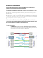
Introduction to the SwiftAXT Stimulators
SwiftAXT (Sweep Interleaved Frequency Domain Testing of Alien X-Talk) technology achieves
sequential measurements through control of measurement timing.
The Stimulator is a high performance, low cost, palm size frequency generator that doubles as a load
termination for use in Alien Crosstalk measurements
For cable vendors, it is for the usage in the lab to have better yield in the manufacturing mass test of
the 10Gbps cables.
For cable installers, it is aimed for the new 10GbE installation and the upgrade of the existing network.
The cable vendors need to have a better yield in the 10G cable manufacturing mass test and ideally the
test is to be done within a short time, 2 minutes or less per link.
To cable installers who perform the new installation in the field, high success rate in the network
implementation is crucial and it boosts the work efficiency if the job could be done with short test time.
To cable installers who carry out the upgrade of existing network, it is expected to have better yield in
the asset upgrade and the task is to be done in short period of test time.
The cable installers need to
• Evaluate a cable and verify its alien cross-talk performance meets requirements for
10GBASE-T.
• Find out the worst disturbing cable from a group of cables affecting a disturbed cable.
• Find out the cable that is most vulnerable to Alien Crosstalk.
6
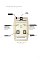
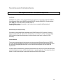
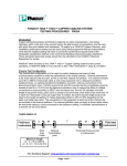
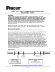
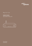
Description of input and output connections
RJ-45
Test Port
Connect to cable
under test
External Power
(12VDC @ 500mA)
Tri Color LED (Remote)
Shows the mode the AXT
stimulator is in.
GREEN – Transmit
Amber – Terminate
Red - Fault
Tri Color LED (Local)
Shows the mode the AXT
stimulator is in.
GREEN – Transmit
Amber – Terminate
Red - Fault
Power Button
Power ON and OFF the
AXT Stimulator Box
Alien Crosstalk Stimulator
Mode Button
Switch Between
Transmit and Terminate
Mode
Battery Compartment
(on rear side)
7
Product Overview
Operation Modes
•
Stimulator supports frequency sweep (transmit), termination and calibration modes.
•
For each configuration, Stimulator will support the following use models:
Frequency Sweep Initiated by the Local Unit
•
In this mode, Stimulator will make continuous sweeps from 1 – 500 MHz. It will set the
Remote Stimulator in termination mode.
•
Local Stimulator can set Remote Stimulator to generate continuous sweeps. In this case, the
Local Stimulator will automatically set in termination mode.
•
Both Stimulator units cannot sweep simultaneously. However, both Stimulator units can be in
termination mode at the same time.
•
Red LED – Fault. Restart Stimulator.
•
Green LED –Transmit Mode
•
Amber LED – Termination Mode (100 Ohms)
Test Initiated by the Remote Unit
•
Details same as test initiated by Local Stimulator
Use Model
•
The Stimulator has a simple user interface with two buttons and two LED indicators.
•
The unit is powered ON/OFF using the Power button.
•
The Mode button sets the operation mode of the Stimulator units. Only one Stimulator per
cable can be transmit mode, but both Stimulators can be in termination mode at the same time.
Communications
•
•
Local Stimulator at power ON:
-
Defaults to termination mode (Local LED – Amber)
-
Waiting for remote stimulator to response (Local LED – blinking Green)
Remote Stimulator at power ON:
-
Defaults to termination mode (Local LED – Amber)
-
Waiting for remote stimulator to response (Local LED – blinking Green)
8
•
If the handshake between the Local and Remote Stimulator units is successful, then
Remote LEDs for both Stimulator units will be solid Amber.
•
The following Mode sequencing is applicable for both Stimulator units (upon successful
handshaking):
-
Pressing the Mode button on Local Stimulator will cause Local Stimulator to instruct
Remote Stimulator to go into termination mode (if it is not in termination mode).
•
Pressing the Mode button again, will cause local Stimulator to change into termination
mode, and instruct the remote Stimulator to sweep (transmit).
•
Pressing the Mode button again, will cause both Stimulator units to go into termination
mode.
•
This pattern repeats.
•
LEDs will change to reflect current status for both Stimulator units.
•
The unit is switched OFF by holding down the Power button for 5 seconds.
9
2
Using the SwiftAXT Stimulator
Powering Up and Down
Preparing the test
Measuring one victim cable and one disturber
Measuring the “6 around 1” set up of the same cable length
Measuring the “6 around 1” set up of the different cable length
10
Using the SwiftAXT stimulators
Preparing for the test – Requirements
WireScope Pro N2640A-200 Category 6A/Class EA Certification Kit with its corresponding accessories
in particularly:
-
2 x N2644A-101 Cat 6A/Class EA Permanent Link SmartProbes
-
2 x N2644A-100 Cat 6A/ Class EA Channel SmartProbes
-
2 x AC/DC Universal Power Adapter
Alien Crosstalk Stimulator Kits N2648A-100, 150 or 200
- Alien Crosstalk Stimulator units
-
AC/DC Universal Power Adapters (supplied)
-
Shielded Patch Cords (supplied)
Software version on WireScope Pro version 2.4.x or higher
If the Alien Crosstalk function is not available, please ensure that the license key is entered. Please
refer to the License Sheet and/or the WireScope Pro User Manual for activation steps.
IMPORTANT
If your WireScope Pro and DualRemote Pro has serial numbers lower than SG47250001 and
SG47260001 respectively and you would like to use the Alien Crosstalk and External (Ambient) Noise
feature, you will need to send the WireScope Pro and DualRemote Pro back to Agilent for calibration.
Please contact your Agilent Sales Representative for more information.
With software release 2.5.x or higher, the calibration status is also shown on the System Information
menu of the WireScope Pro.
Shielded patch cords MUST be used with the Stimulators.
Powering Up and Down
Insert the AC/DC adapter connector to the dc input which is located on the top right of the Alien
Crosstalk Stimulator box.
Alternatively, the Alien Crosstalk stimulator box can also be powered by a 9V battery (not supplied).
The recommended battery capacity is at least 250 mAh.
To operate using battery, slide open, the battery cover located on the back of the stimulator. Insert the
battery into the battery slot, noting the battery polarity. Slide the cover back into place.
To turn on the stimulator, press the power on/off button
To turn off the stimulator, press and hold the power on/off button.
11
CAUTION
Use only the 12V AC/DC power adapter supplied with your Alien Crosstalk
Stimulator. Using an incompatible power adapter can damage the equipment
and void its warranty.
Please use the supplied power cord to disconnect the 12V AC/DC power
adapter from mains.
WARNING
Never connect the Alien Crosstalk Stimulator’s test port to a voltage source
such as a telephone jack. Excessive voltages can damage the stimulator and
void your warranty.
12
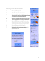
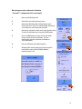
Measuring one victim cable and one disturber
1
Power up the WireScope Pro
2
Select Alien Crosstalk on the main menu
3
Connect the WireScope Pro and Dual Remote to the
Victim cable. Press Start Test and WireScope will perform
an Insertion Loss measurement on the cable.
4
Connect the Stimulator to both ends the disturber cables.
Turn on the Stimulators by pressing the POWER button.
5
Press the MODE button to select the Transmit mode
(Green) on the local stimulator. This also automatically
switches the remote stimulator to Termination Mode.
6
Press the OK button on the WireScope Pro
7
WireScope Pro will show the measured victim cable’s
insertion loss value in dB at 250 MHz. Modify if
required and press OK
13
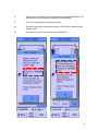
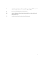
8
Switch the local stimulator to Termination Mode by pressing the MODE button. This
will automatically switch the remote stimulator to Transmit Mode.
9
Press OK on the WireScope Pro to continue the test
10
Since there are only one victim and one disturber, click No when asked to add more
disturber cables.
11
Save the test results and view the results on WireScope Pro
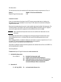
14
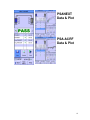
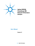
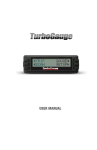
PSANEXT
Data & Plot
PSA-ACRF
Data & Plot
15
Measuring one victim cable and six disturber
“6 around 1” configuration of the same length
1
Power up the WireScope Pro
2
Select Alien Crosstalk on the main menu
3
Connect the WireScope Pro and Dual Remote to the
Victim cable. Press Start Test and WireScope will perform
an Insertion Loss measurement on the cable.
4
Connect the stimulators to both ends of the disturber cables.
Turn on all Stimulators by pressing the POWER button.
5
Press the MODE button to select the Transmit mode
(Green) on the all 6 local stimulators. This also
automatically switches the remote stimulators to
Termination Mode
6
Press the OK button on the WireScope Pro
7
WireScope Pro will show the measured victim cable’s
insertion loss value in dB at 250 MHz. Modify if
required and press OK
16
8
Switch the local stimulators to Termination Mode by pressing the MODE button. This
will automatically switch the remote stimulators to Transmit Mode.
9
Press OK on the WireScope Pro to continue the test
10
Since the 6 disturbers are tested at one go in parallel, click No when asked to add
more disturber cables.
11
Save the test results and view the results on WireScope Pro
17
Measuring one victim cable and six disturber
“6 around 1” configuration of the different length
When the cables under test are of different length, the cables with the same lengths should be
group together for sequential testing.
1
Power up the WireScope Pro
2
Select Alien Crosstalk on the main menu
3
Connect the WireScope Pro and Dual Remote to the
Victim cable. Press Start Test and WireScope will perform
Insertion Loss measurement on the cable.
4
Connect the stimulators to both ends of the disturber cables.
Turn on the Stimulators in groups by pressing the
POWER button.
5
Press the MODE button to select the TRANSMIT mode
(Green) on the group of local stimulators with the same length.
This also automatically switches the remote stimulators to
Termination Mode
6
Press the OK button on the WireScope Pro
7
WireScope Pro will show the measured victim cable’s
insertion loss value in dB at 250 MHz. Modify if
required and press OK
18
8
Switch the local stimulators to Termination mode by pressing the MODE button. This
will automatically switch the remote stimulators to Transmit mode.
9
Press OK on the WireScope Pro to continue the test
10
When asked to add more disturber, click YES.
11
Turn on the Stimulators on next group of disturber cables.
Similarly, press the MODE button to switch the local Stimulator to Transmit Mode.
12
Press the OK button on the WireScope Pro
13
Enter the Insertion Loss (dB) @ 250 MHz of the group of disturber cables and press OK
14
Switch the local stimulators to Termination mode by pressing the MODE button. This
will automatically switch the remote stimulators to Transmit mode.
15
Repeat step 10 to 14 until all groups of disturber cables are covered.
16
Save the test results and view the results on WireScope Pro
19
3
Specifications
Technical
Electrical
Environmental
Physical
Technical Construction File for Radiated Emission
20
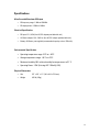
Specifications
Alien Crosstalk Stimulator RF Output
•
RF frequency range: 1 MHz to 500 MHz
•
RF output power: 0.5dBm ±1.0dBm
Electrical Specification
•
DC Input: 12 V, 0.5A (Use AC/DC adaptor provided with unit)
•
AC Power adapter: 100 – 240V ac (Use AC/DC adapter provided with unit)
•
Battery: 9V Battery, not supplied (recommended capacity at least 250 mAh)
Environmental Specification
•
Operating temperature range: 10°C to + 40°C
•
Storage temperature range: - 40°C to +70°C
•
Maximum humidity: 95% relative humidity for temperatures to 31° C
•
Operating Power: 1.3W (Existing AXT :130mA @ 10V)
Physical Dimensions
•
Size
5.5” x 3.6” x 1.1” (140 x 91.4 x 27.9 mm)
•
Weight
0.35 lb (160g)
21
22
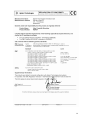
Technical Construction File for Radiated Emission
EMC Regulatory Instruction - Site Attenuation Requirement
Introduction
All EMC relevant products must comply with the local requirements, internationally with the CISPR 11,
in the European Union with the EMC Directive 89/336/EEC including 93/68/EEC, in Canada with the
ICES/NMB-001, in Australia with the AS/NZS CISPR 11.
For the N2648A, the derived standards as well as the classes are noted in the Declaration of
Conformity in this Guide.
EU-Conformity from a Competent Body
For products that do not fulfill the requirements the EU EMC Directive (§ 10.2) requires a Technical
Construction File (TCF) with a Declaration of Conformity or a Certificate issued by a Competent Body
(CB). For the Site Attenuation Requirements and the methods stated herein a review by a CB is
mandatory.
Technical Rational
The systems concerned meet all requirements with the exception of Radiated Emissions of CISPR11
class A or the corresponding local standard. The measurement environment with specified high-speed
test data traffic through open connections causes radiated electromagnetic emission above the
required limits.
In order to meet the requirements appropriate preventive measures for the site must be considered and
established before the systems will be switched on for its intended application. The methods described
herein are sufficient to keep the system within the required limits of the standard.
23
Site Attenuation:
This document describes the methods for Site Attenuation to meet the requirements of Class A.
Product:
Required Target Site Attenuation:
N2648A - Alien Crosstalk Stimulator
9 dB
Installation Instruction
If your site received permission from a local (PTT) agency to exceed the levels of radiation, this
exceeded level has to be considered. In case of e.g. +10 dB, subtract this ratio from the Required
Target Site Attenuation.
Based on the location where the system is to be installed, obtain the Available Site Attenuation. The
calculating method is described in the section Calculating Method. Preventive measures might be
necessary by optimization of the equipment and/or additional walls to be installed.
Note:
After installation of the preventive measures the available Site Attenuation must be
calculated
The available Site Attenuation must be higher than the Required Target Site Attenuation value!
If not, additional measures as a shielded Cabin with specified shielding performance must be
considered.
Other shielding methods as conductive wallpaper, metal walls etc. require an approval test ("in situ")
by a local (PTT) agency. Appropriate arrangements have to be organized.
Install the system as described in the Installation Guide.
The product installation will then meet the requirements for radiation levels of Class A of CISPR 11 or
the corresponding local standard.
Calculating Method
To obtain the Required Target Site Attenuation at the customer site:
1. Available Site Attenuation:
A=n*W+X
A
n
W
X
=
=
=
=
Available Site Attenuation in dB
number of concrete walls within distance D
10 dB (attenuation of a concrete wall without openings)
attenuation reached by distance between equipment
and exterior Wall plus 30 m to estate border
2. Attenuation X
X = 20 * log (D/30)
D = real estate border distance in m
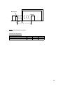
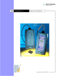
24
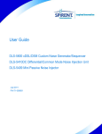
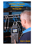
Concrete Wall (W)
Building
Measuring Point
Equipment
30 m
D
Figure 1: Site attenuation calculation
Calculation for this product:
Req. Target Site Attenuation in dB
9
9
Walls/n
0
1
X in dB
9
-1
D in m
85
27
25
www.agilent.com
Agilent Technologies, Inc. 2007
Printed in Singapore
26