1
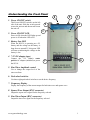
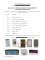
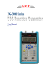
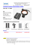
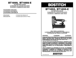
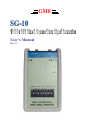
GME User’s Manual Rev 1.2 TEST INSTRUMENT SAFETY GUIDELINES WARNING An electrical shock of over 10 milliamps of current to pass through the heart will stop most human heartbeats. Voltage as low as 35 volts dc or ac rms should be considered dangerous and hazardous since it can produce a lethal current under certain conditions. Be sure to observe following safety precautions: 1. Do not expose high voltage needlessly in the equipment under test. Remove housings and covers only when necessary. Turn off equipment while making test connections in high-voltage circuits. Discharge high-voltage capacitors after removing power. 2. If possible, familiarize yourself with the equipment being tested and the location of its high voltage points. However, remember that high voltage may appear at unexpected points in defective equipment. 3. Use an insulated floor material or a large, insulated floor mat to stand on, and an insulated work surface on which to place equipment; make certain such surfaces are not damp or wet. 4. When using a probe, touch only the insulated portion. Never touch the exposed tip portion. 5. When testing ac powered equipment, remember that ac line voltage is usually present on some power input circuits such as the on-off switch, fuses, power transformer, etc. any time the equipment is connected to an ac outlet, even if the equipment is turned off. Limited One-Year Warranty GME Technology warrants to the original purchaser that this product and the component parts thereof, will be free from defects in workmanship and materials for a period of one years from the data of purchase. GME Technology will, without charge, repair or replace, at its’ option, defective product or component parts. Returned product must be accompanied by proof of the purchase date in the form a sales receipt. Term and Conditions The warranty period is based upon the invoice date of the original purchase by the end-user. Warranty only applies to defects in materials and/or workmanship, which occur during normal use. Warranty does not apply to those products that are damaged due to misuse, abuse, negligence or modification. Warranty does not extend to any damage that occurs in shipment or due to natural phenomenon (i.e. lightning or line surges). Warranty will be voided if the original serial number on the product is removed by accident or intentionally This warranty gives you specific rights and you may have other rights, which vary from state-to-state. Service & Repair The following are procedure for returning a GME product for servicing and repair. Turn around time for repair is normally within five (5) working days excluding shipping time. RMA Procedure Before sending your GME product in for service, be sure to contact GME Technology first to obtain a RMA number. If your product is still under warranty, please send in the product along with a copy of the receipt showing the date when the product was purchased. If the warranty has already expired, please ask for the repair cost when you contact GME Technology for the RMA number and include a check or money order for the repair cost when you send in the product. Please make check payable to: GME Technology You may send your GME product to our service & repair department at: GME Technology ATTN: Service & Repair Department 380 S. East End Ave., #H Pomona, CA 91766 Be sure to include a note showing your RMA number, your name, telephone number, return address, and a description of the problem with the product. For the most recent support information, please visit GME Technology website at www.gmetechnology.com/support Table of Contents Page Introduction …………………………………………………………………………. 1 Item Checklist ……………….…………………………………………………….... 1 Features ……………………………………………………………………………... 1 Understanding the Front Panel ……………………………………………………...... 2 Basic Operation ….………………………………………………………………….... 3 Specifications ………………….……………………………………………………... 4 GME Product Information …………………………………………………………… 5 Notes ……….………………….…………………………………………………….. 6-7 Introduction Thank you for purchasing the SG-10 10 MHz DDS Sine & Square Wave Signal Generator. Based on the latest advances in DDS technology, the SG-10 is a high precision sine and square wave signal generator. The SG-10 utilizes microprocessor control that delivers clean and accurate DC to 10MHz waveforms with crystal frequency accuracy of +/- 50ppm and 0.1 Hz frequency resolution. Eight push wheel switches allow simple and accurate frequency setting. There are two BNC connectors for separate sine and square wave output. The SG-10 also features variable sine wave amplitude control. Item Checklist SG-10 10 MHz DDS Sine & Square Wave Signal Generator One protective rubber holster One 7.5 V AC power adaptor One User’s Manual Features 10 MHz waveform for sine and square wave DDS technology with microprocessor control for clean and accurate waveform Variable sine wave amplitude control Eight push wheel switch for simple and accurate frequency setting Standard BNC connectors for sine and square wave output AC adaptor power source or standard 9V battery operation Low battery indicator Handheld enclosure with protective rubber boot Ideal for on-the-bench and in-the-field testing Easy to use, lightweight, and portable Understanding the Front Panel 8 9 3 1. Power ON/OFF switch This Power ON/OFF switch is on the left side of the unit. Slide the switch upward to turn the unit on and downward to turn the unit off. 2. Power ON/OFF LED 2 4 1 Power is ON when the LED lights up and power is off when the LED is off. 3. Battery Low LED 5 When the HG139 is operating on a 9V battery and the voltage on the battery is drop down to around 5V, this green LED will turn on indicating the voltage on the battery is low. 4. 7.5V DC adaptor input Connect the 7.5V 200mA center positive AC adaptor (included) to power the SG-10. 6 7 5. Sine Wave Amplitude control Use to change the output level of the sine waveform. 6. Push wheel switches Use these eight push wheel switches to set the desire frequency 7. Frequency Display Display the frequency of the current output for both sine wave and square wave. 8. Square Wave Output (BNC connector) Output the square wave signal for the frequency selected 9. Sine Wave Output (BNC connector) Output the sine wave signal for the frequency selected www.gmetechnology.com 1 Basic Operation CAUTION: The signal generator output should never be connected to a signal injection point. Excessive voltage applied to the signal generator output can cause internal damage to the signal generator. 1. Slide the power switch to turn on the SG-10. 2. Set the desire output frequency using the eight push wheel switches. 3. Connect the SG-10 outputs using BNC cables to the desire test points. 4. Adjust the output level of the sine waveform using the amplitude control www.gmetechnology.com 2 Specifications Waveforms Sine, Square Range Frequency Resolution Crystal Accuracy DC to 9.9999999 MHz 0.1 Hz steps +/- 50ppm Sine wave output Square wave output Output impedance 5 Vp-p (no load) with variable amplitude control 5 Vp-p 50 ohm Power one standard 9V battery OR 6V - 9V AC adaptor (150mA, 5.5mmx2.1mm center positive) Dimension Weight 5.7"(H) x 3.8"(W) x 1.5"(D) 1 lb www.gmetechnology.com 3 WWW.GMETechnology.COM For product updates and information CHECK OUT THESE OTHER TEST EQUIPMENT AVAILABLE FROM GME GME offers many different types of electronic test equipment to suit your needs. Here are some of the test equipment products we offer. Model Description HG139 HDTV Pattern Generator SG-10 10 MHz DDS Signal Generator 236 In-Circuit ESR & DCR Capacitor Tester PG-16A NTSC & Monitor Tester (Handheld Model) PG-68 NTSC & Monitor Tester (Benchtop Model) PG-38 NTSC Pattern Generator MT-160 Computer Monitor Tester LC200 Digital LC Meter C350 Capacitance Meter Other products such as digital / analog panel meters, step motor drivers are also available. Please visit our website at www.gmetechnology.com for complete detail. www.gmetechnology.com 4 Notes www.gmetechnology.com 5 Notes www.gmetechnology.com 6