1
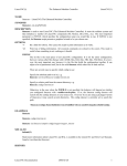
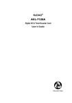
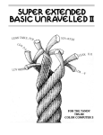
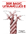
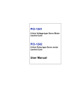
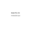
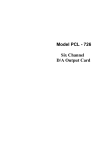
Model PCL-720
Digital I/O &
Counter Card
PCL-720 Digital I/O and Counter Card
USER'S MANUAL
This documentation is copyrighted 1990 by Advantech
Co., Ltd. All rights are reserved. Advantech Co., Ltd.
Reserves the right to make improvements in the
products described in this manual at any time without
notice.
No part of this manual may be reproduced, copied,
translated or transmitted, in any form or by any means
without the prior written permission of Advantech Co.,
Ltd. Information provided in this manual is intended to
be accurate and reliable. However, Advantech Co.,
Ltd. assumes no responsibility for its use; nor for any
infringements of rights of third parties which may
result from its use.
PC-LabCard is a trademark of Advantech Co., Ltd. IBM
and PC are trademarks of international Business
Machines Corporation. MS-DOS is a trade mark of
Microsoft Corporation. BASIC is a trademark of
Dartmouth College. Intel is a trademark of Intel
Corporation.
Part No. 2003720000 Rev. C1
Printed in Taiwan Mar. 1990
TABLE OF CONTENTS
CHAPTER 1 GENERAL INFORMATION . . . . . . . . . . . . . . . . . . . . . . . 1
1.1. Introduction . . . . . . . . . . . . . . . . . . . . . . . . . . . . . . . . . . . . . . 1
1.2. Features, Application and Specifications . . . . . . . . . . . . . . 1
CHAPTER 2 INSTALLATION . . . . . . . . . . . . . . . . . . . . . . . . . . . . . . .
2.1. Initial Inspection
...................................
2.2. Base Address Selection . . . . . . . . . . . . . . . . . . . . . . . . . . . . .
2.3. Clock Frequency Setting . . . . . . . . . . . . . . . . . . . . . . . . . . . . .
2.4. Installing into the PC . . . . . . . . . . . . . .. . . . . . . . . . . . . . . . . .
5
5
5
7
7
CHAPTER 3 SIGNAL CONNECTION . . . . . . . . . . . . . . . . . . . . . . . 9
3.1. Connector Pin Assignment . . . . . . . . . . . . . . . . . . . . . . . . . . . 9
3.2. Timer/Counter Signal Pads . . . . . . . . . . . . . . . . . . . . . . . . . . 11
3.3. Clock Source Pads . . . . . . . . . . . . . . . . . . . . . . . . . . . . . . . . . . 11
3.4. Strobe of Digital Input . . . . . . . . . . . . . . . . . . . . . . . . . . . . . 12
CHAPTER 4 PROGRAMMING . . . . . . . . . . . . . . . . . . . . . . . . . . . . . .
4.1. Register Structure and Format . . . . . . . . . . . . . . . . . . . . . . . .
4.2. Digital UO Programming . . . . . . . . . . . . . . . . . . . . . . . . . . . . .
4.3. Programmable Interval Timer . . . . . . . . . . . . . . . . . . . . . . . .
4.3.1. The Intel 8253 . . . . . . . . . . . . . . . . . . . . . . . . . . . . .
4.3.2. The Control Byte . . . . . . . . . . . . . . . . . . . . . . . . . . .
4.3.3. Mode Definitions . . . . . . . . . . . . . . . . . . . . . . . . . .
4.3.4. Loading and Reading The Counters . . . . . . . . . . .
13
13
14
15
15
16
17
20
APPENDIX A I/O PORTADDRESS MAP . . . . . . . . . . . . . . . . . . . . . 23
CHAPTER 1 GENERAL INFORMATION
1.1. Introduction
The PCL-720 Digital I/O and Counter Card is a PC add-on card that offers you
32 digital input channels , 32 digital output channels and 3 counter/timer
channels. All digital input and output channels are TTL/DTL compatible.
Each digital input or output channel corresponds to a certain bit of the I/O port
of the PC and it is very easy to program the function of this card.
To make your application easier, external daughter boards, PCLD-782, PCLD785 and PCLD-786, are designed to work with the digital input/output ports of
the PCL-720. The PCLD-782 is a 16-channel opto-isolated digital input board
which provides an easy way to input digital data to the PCL-720 when the
ground isolation is required The PCLD-785 is a 16-channel relay output board
which can be driven by the digital output of the PCL-720 card. The PCLD-786
is an SSR board which can control AC power up to 8 channels.
An on-board Intel 8253 programmable interval timer provides three independent
16 bit down counters as timing sources for various applications. Also, a
breadboard area is available for customized interface circuits.
The PCL-720 (after rev. C) also offers on-board clock sources those are 1 MHz,
100 KHz and 10 KHz and these frequencies can be double, half or quartered by
setting jumpers.
1.2 Features, Application and Specifications
Features :
Ÿ
32 digital input channels
Ÿ
32 digital output channels
Ÿ
High output driving capacity
General Information
PCL-720
Ÿ
Low input loading
Ÿ
3-channel programmable interval timer
Ÿ
On-board crystal based clock source
Ÿ
Breadboard area for customized circuits
Applications
Ÿ
Industrial ON/OFF control
Ÿ
Contact closure monitoring
Ÿ
Switch panel status sense
Ÿ
BCD interface
Ÿ
Digital I/O control
Ÿ
Industrial automation
Ÿ
Laboratory automation
Ÿ
Period and pulse width measurement
Ÿ
Event and frequency counting
Specifications
Ÿ
Dimensions:
Ÿ
Bus :
9" x 4.125"
22.8 cm x 10.48 cm
IBM PC bus
Ÿ
Slot :
One 62-pin slot
Ÿ
I/O Port Address : Hex 200 - hex 3F8
PCL-720
General Information
Ÿ
Breadboard Area: 540 (30 X 18) plated-through "donuts"
holes, each with a.036' hole on 0.10"
centers.
Ÿ
Digital Input
Input Low Level :
Input High Level:
Input Loading :
Input Hysteresis :
Ÿ
Min. -0.5V, max. 0.8V
Min. 2.0V, max. 5.0V
Max 0.2 mA at 0.4V
Typical 0.4V, min. 0.2V
Digital Output
Output Low Level : Max. 0.5V at 24 mA
(sink) Max. 0.4V at 12 mA
Output High Level : Min. 2.0V at 15 mA
(source) Min. 2.4V at 3 mA
Driving Capacity :
15 TTL's at least
CHAPTER 2 INSTALLATION
2.1. Initial Inspection
Inside the shipping container, you should find this operating manual and the
PCL-720 card.
The PCL-720 is carefully inspected both mechanically and electrically before
shipment. It should be free of marks and scratches and in perfect electrical
order on receipt.
Remove the PCL720 interface card from its protective packaging by grasping
the metal rear panel. Keep the anti-vibration package since it may be used to
return the card if it needs repair. The package may also be used if the card is
stored outside of the computer.
The board should be handled only by the edges. The integrated circuits on
the board can be damaged by static electric discharge. The package
2.2. Base Address Selection
Most of the peripheral devices and the interface adapters in the PC are
controlled and sensed using the digital input and output pens. These ports are
addressed using the I/O port address space of the 8088 or 80286
microcomputer.
The I/O port base address for the PCL-720 is selectable by the setting of a DIP
switch (SW1). Valid addresses are from hex 200 to hex 3F8. Refer to Figure
2.1 for the location of the DIP switch (SW1).
Installation
PCL-720
Figure 2.1 The PCL-720 Card
The required switch settings for various base addresses are illustrated
as below :
Note :
-
ON=0, OFF=1
"X" means "don't care"
1..8 are switch positions
A3..A8 correspond to address Lines of the PC bus. A9 is
hard-wired to be 1.
- * means factory setting
PCL-720
Installation
--------------------------------------------I/o port
Switch position
address
1
2
3
4
5
6
(Hex)
A8
A7
A6
A5
A4 A3
--------------------------------------------200-207
0
0
0
0
0
0
208-20F
0
0
0
0
0
1
.
.
* 2A0-2A7
0
1
0
1
0
0
2A8-2AF
0
1
0
1
0
1
.
.
2E8-2EF
0
1
1
1
0
1
.
2F8-2FF
0
1
1
1
1
1
3E8-3EF
1
1
1
1
0
1
3F8-3FF
1
1
1
1
1
1
---------------------------------------------
2.3. Clock Frequency Setting
The PCL-720 offers on-board clock sources those are 1 MHz, 100 KHz and 10
KHz when a jumper is placed on the position marked "xl" of JP1. These
frequencies can be double, half or quartered by placing a jumper on position
"x2", "x1/2" or "xl/4" of the JP1. For example, a frequency source of 25 KHz
can be got from the pad marked "100K" when placing the jumper on position
"x1/4" of the JP1 as below.
oo
* oo
oo
oo
JP1
x2
xl
x1/2
x1/4
* : Factory setting
2.4. Installing into the PC
POWER MUST ALWAYS BE SWITCHED OFF when removing or inserting the
PCL-720 card and connecting or disconnecting cables.
Use a screw driver to remove the cover mounting screws from the rear of the
system unit.
Installation
PCL-720
Slide the system unit's cover away from the rear and to the front. When the
cover will go no further, tilt it up, remove it from the base, and set it aside.
The PCL-720 is configured at the factory for the IBM PC, PC/XT, PC/AT and ah
IBM PC compatibles. If you need further changes to the configuration please
refer to Chapter 2. Installation.
Use a screw driver to remove the screw that secures the expansion slot cover.
Save the screw for installation of the interface card.
The two rear connectors should be pressed through the rear panel first, then
press the card carefully into the main board expansion slot.
Secure the PCL-720 with the 3/16" mounting screw, then attach and appropriate
cable to the connector.
Slide the system unit's cover back on. Align the system unit tabs with the
cover holes and reinstall the cover mounting screws.
CHAPTER 3 SIGNAL CONNECTION
3.1. Connector Pin Assignment
The PCL-720 card is equipped with two 20-pin insulation displacement (mass
termination) connectors accessible from the rear plate and three other 20-pin
insulation displacement connectors on board. All these connectors can be
connected to flat cables of the same type. Please refer to Figure 2.1 for the
location of each connector.
The following diagrams below show their pin assignments.
Note :
- D/O means digital output
- D/I means digital input
- GND means ground
- CLK is the clock input for the 8253
- GATE is the gate input for the 8253
- OUT is the signal output of the 8253
- STROBE is the external signal to latch the D/I data
Connector 1:
Signal Connection
Connector 2:
Connector 3:
Connector 4:
PCL-720
PCL-720
Signal Connection
Connector 5:
3.2. Timer/Counter Signal Pads
To make the wiring of the 8253 counter input and output signals easier for
user's application, all the “CLK”, “GATE” and “OUT” signals of the three 16
bit counters have their soldering pads. These pads have exactly the same
signals as those on connector CN5. For example, if a user wants to use the
output of counter 0 (OUT0) as the clock source of counter 1 (CLK1), he (she)
can place a wire between the pads marked “OUT0” and “CLK1”.
JP2
o CLK0
o GATE0
o OUT0
o CLK1
o GATE1
o OUT1
o CLK2
o GATE2
o OUT2
3.3. Clock Source Pads
There are 3 pads offer clock sources of 1MHz, 100KHz and 10KHz when the JP1
is inserted with a jumper at the position 'xl'. These frequencies can be double,
half or quartered by placing the jumper on the position 'x2', 'x1/2' or 'x1/4' of the
JP1. The user can link one of the clock source to the clock input of the 8253
timer/counter by placing a wire between the corresponding pads. For example,
if a user want that the counter 2 has 1 MHz clock input, he(she) can just solder
a wire between pads “1M” and “CLK2” and place a jumper on
Signal Connection
PCL-720
position 'xl' of the JP1.
3.4. Strobe of Digital Input
The digital input connectors, CN2 and CN4, have "STROBE" signals at pin-20.
The "STROBE" input signals are used to gate the digital input signal DI0 to
DI15 and DI16 to DI31.
When the "STROBE" input is high or left open, the data which the PC reads
from the corresponding input port is the current status of the digital input pins.
When the "STROBE" input goes from high to low, the digital input data is
latched in the input buffer and the PC reads the data which is the input status
on the falling edge of "STROBE". Normally, the "STROBE" pins are left open
and the digital input ports have the current status of the digital input pins. If
the user wants to read the status of the digital input pins when an certain
signal is high, then he (she) can connect the signal to the "STROBE" pins to
gate the input data.
"STROBE 0" is used to gate the digital input signal on CN2, D/I 0 to
D/I 15 and "STROBE 1" is for the input signal on CN4, D/I 16 to
D/I 31.
Strobe
D/I data
------------------------High
Transparent
Low
Latched
CHAPTER 4 PROGRAMMING
4.1. Register Structure and Format
The most important issue in programming the PCL720 is understanding the
meaning of the 8 registers addressable from the selected I/O port base address.
The following diagram shows the relative location of each register as to the
base address and its usage.
Note :
- LSB means least significant byte
- MSB means most significant byte
Write
Read
-----------------------------------base +0
D/O 0 - 7
D/I 0 – 7
base +1
D/O 8 - 15 D/I 8 -15
base +2
D/O 16 -23 D/I 16 -23
base +3
D/O 24 - 31 D/I 24 -31
base +4
LSB or MSB of COUNTER 0
base +5
LSB or MSB of COUNTER 1
base +6
LSB or MSB of COUNTER 2
base +7
CONTROL BYTE
The format and structure of each register are discussed as follows.
Note :
base +0
- Bit 0 is the least significant bit.
- OP stands for operation.
If OP=read, bit 0-7 of this byte correspond to channel 0-7
of the 32 digital input channels.
If OP=write, bit 0-7 correspond to channel 0-7 of the 32
digital output channels.
base +1 If OP=read, bit 0-7 correspond to D/I channel 8-15.
Programming
PCL-720
If OP=write, bit 0-7 correspond to D/O channel 8-15
base +2
If OP=read, bit 0-7 correspond to D/I channel 16-23
If OP=write, bit 0-7 correspond to D/O channel 16-23.
base +3
If OP=read, bit 0-7 correspond to D/I channel 24-31.
If OP=write, bit 0-7 correspond to D/O channel 24-31.
base +4
If OP=read, this byte can be either the least significant
byte or the most significant byte of the 16-bit long count
for counter O, depending on the setting of the Control
Byte.
If OP=write, this byte can be either the least significant
byte or the most significant byte of the 16-bit long count
for counter O, depending on the setting of the Control
Byte.
base +5
The usage of this byte is the same as base +4, except it is
for counter 1.
base +6
The usage of this byte is the same as base +4, except it is
for counter 2.
base +7
Control Byte. The Control Byte Register can only be
written to and is used to define the operation of the
counters. A detailed explanation of the format of this
control byte is presented in Section 4.3.2.
4.2. Digital I/O Programming
On the PCL-720 card, 32 digital input channels and 32 digital output channels
are provided. Four I/O port addresses (started from BASE +0) are reserved for
accessing these channels.
The four addresses are allocated as:
PCL-720
Programming
BASE +0
BASE +1
BASE +2
BASE +3
Channel 0-7
Channel 8-15
Channel 16 -23
Channel 24 -31
A read operation on any of these I/O ports will read in the value of the 8
corresponding digital input channels. In BASIC, a statement such as "VALUE
= INP(ADDRESS)" will do the job.
A write operation on any of these I/O ports will set the desired value on the 8
corresponding digital output channels. A BASIC statement like "OUT
ADDRESS, VALUE" can be used to accomplish the work.
4.3. Programmable Interval Timer
4.3.1. The Intel 8253
The Intel 8253 Programmable interval timer is used on the PCL-720 card. It is
organized as 3 independent 16-bit counters, each with a count rate of up to 2.6
MHz. Each counter can be programmed to have a count from 0 up to 65,535.
Each counter can also be set to operate in one of the 6 different modes of
operation. All modes of operation are software programmable.
The main counter/timer functions that can be implemented with the
8253 are :
Ÿ
Ÿ
Ÿ
Ÿ
Ÿ
Ÿ
Programmable Rate Generator
Event Counter
Real Time Clock
Digital One-Shot
Time Delay Generator
Square Wave Generator
For more information regarding the 8253 programmable interval timer, please
refer to the Intel Microsystem Components Handbook (Microprocessors and
Peripherals Volume II).
Programming
PCL-720
4.3.2. The Control Byte
The 8253 programmable interval counter occupies 4 UO address locations in
the PCL-720 VO address map as mentioned in Section 4.1. Their addresses are:
Address
------BASE+4
BASE+5
BASE+6
BASE+7
Register
---------Read/write
Read/write
Read/write
Write only
Type Description
---------------Counter 0
Counter 1
Counter 2
Control Byte
Before loading or reading any of the individual counters, the 8253 control byte
must be loaded with data setting the counter selected, the operating mode, the
type of read or write operation that will be performed, and the modulus (binary
or BCD).
The format of the Control Byte is:
bit
7
6
5
4
3
SC1 SCO RL1 RLO M2
2
1
M1 MO
0
BCD
SC1-0 : Select counter.
SC1
--0
0
1
1
SC0
--0
1
0
1
Counter
------0
1
2
Illegal
RL1-0 : Select the read or load operation
RL1
--0
0
1
1
RLO
--0
1
0
1
Operation
---------------Counter latch
Read/load LSB
Read/load MSB
Read/load LSB first, then MSB.
PCL-720
Programming
The Counter latch command is used to read back the value of a counter without
disturbing the count in progress.
M2-0 : Select the operating mode
M2
--0
0
X
X
1
1
M1
--0
0
1
1
0
0
M0
--0
1
0
1
0
1
Mode
---0
1
2
3
4
5
See Section 4.3.3. for the definition of each mode.
BCD : Selects binary or BCD counting
BCD
---0
1
Type
----------------------Binary counter l6-bits
BCD counter
If the modulus is set to be binary, the count can be any number from 0 up to
65,535. If the modulus is set to be BCD (binary coded decimal), then the count
can be set as any number from 0 to 9,999.
4.3.3. Mode Definitions
The definitions of the six operating modes are described here. Refer to the
data sheet of the 8253 for more details.
Mode 0 : Interrupt on Terminal Count
The output will be initially low after the mode set operation. After the
count is loaded into the selected count register, the output will remain
Programming
PCL-720
low and the counter will count. When terminal count is reached, the
output will go high and remain high until the selected counter is
reloaded with the mode or a new count is loaded. The counter
continues to decrement after terminal count has been reached.
Rewriting a counter register during counting results in the following:
1. Write 1st byte stops the current counting.
2.
Write 2nd byte starts the new count.
Mode 1 : Programmable One-Shot
The output will go low on the count following the rising edge of the
gate input. The output will go high on the terminal count. If a new
count value is loaded while the output is low, it will not affect the
duration of the one-shot pulse until the succeeding trigger. The
current count can be read at any time without affecting the one-shot
pulse.
The one-shot is retriggerable, hence the output will remain low for the
full count after any rising edge of the gate input.
Mode 2 : Rate Generator
Divide by N counter. The output will be low for one period of the input
clock. The period from one output pulse to the next equals the number
of input counts in the counter register. If the count register is reloaded
between output pulses, the present period will not be affected, but the
subsequent period will reflect the new value.
The gate input, when low, will force the output high. When the gate
input goes high, the counter will start from the initial count. Thus, the
gate input can be used to synchronize the counter.
When this mode is set, the output will remain high until after the count
register is loaded. The output then can also be synchronized by
software.
PCL-720
Programming
Mode 3 : Square Wave Rate Generator
Similar to mode 2, except that the output will remain high until one half
the count has been completed (for even numbers) and go low for the
other half of the count. This is accomplished by decrementing the
counter by two on the falling edge of each clock pulse. When the
counter reaches terminal count, the state of the output is changed and
the counter is reloaded with the full count and the whole process is
repeated.
If the count is odd and the output is high, the first clock pulse (after the
count is loaded) decrements the count by 1. Subsequent clock pulses
decrement the count by 2. After timeout, the output goes low and the
full count is reloaded. The first clock pulse (following the reload)
decrements the counter by 3. Subsequent clock pulses decrement the
count by two until timeout. Then the whole process is repeated. In
this way, if the count is odd, the output will be high for (N+1)/2 counts
and low for (N-1)/2 counts.
Mode 4 : Software Triggered Strobe
After the mode is set, the output will be high. When the count is
loaded, the counter will begin counting.
On terminal count, the
output will go low for one input clock period, then will go high again.
If the count register is reloaded during counting, the new count will be
loaded on the next CLK pulse. The count will be inhibited while the
GATE input is low.
Mode 5 :Hardware Triggered Strobe
The counter will start counting after the rising edge of the trigger input
and will go low for one clock period when the terminal count is reached.
The counter is retriggerable. The output will not go low until the full
count after the rising edge of any trigger.
Programming
PCL-720
4.3.4. Loading and Reading The Counters
The programming procedure for the 8253 is very flexible.
conventions need to be remembered :
Only two
1.
For each Counter, the Control Byte must be written before the initial
count is written.
2.
The initial count must follow the count format specified in the Control
Byte (LSB only, MSB only or LSB first then MSB).
Since the Control Byte register and the three counters have separate addresses
and each Control Byte specifies the Counter it applies to (by SC1 and SCO), no
special instruction sequence is required. Any programming sequence that
follows the conventions above is acceptable.
A new initial count may be written to a Counter at any time without affecting
the Counter's programmed mode in any way. Counting will be affected as
described in the mode definitions. The new count must follow the
programmed count format.
If a counter is programmed to read/load two-byte counts, the following
precaution applies: A program must not transfer control between writing the
first and second byte to another routine which also writes into that same
counter. Otherwise, the counter will be loaded with an incorrect count.
Some programming examples in BASIC:
10 'set base address
20 BASE%=&H2A0
30 'control byte for Counter 0:
40 'write LSB only, mode=3, BCD=0
50 OUT BASE%+7,&H16
60 'output LSB=10
70 LSB%=10
80 OUT BASE%+4,LSB%
90 'control bytes for Counter 1 and 2
100 'write LSB first, then MSB, mode=l, BCD=O
110 OUT BASE%+7,&H72 'for Counter 1
120 OUT BASE%+7,&HB2 'for Counter 2
130 'X is the count for both counters
140 X%=1000
PCL-720
150
160
170
180
190
200
Programming
MSB%=INT(X%/256) 'figure out the MSB
LSB%=X%-(256tMSB$) 'figure out the LSB
OUT BASE%+5,LSB% 'load Counter 1 LSB
OUT BASE%+5,MSB% 'MSB
OUT BASE&+6,LSB% 'load Counter 2 LSB
OUT BASE%+6,MSB% 'MSB
It is often desirable to read the value of a Counter without disturbing the count
in progress. Usually, the method used is called the Counter Latch Command
method which allows the user to read the latched count value of the selected
Counter.
The command is written into the Control Byte Register and has the format
shown below. The command applies to the Counter selected by the SC1 and
SC2 bit in the Control Byte. And the command distinguishes itself from other
commands by setting bit 4 and 5 to 0.
bit
7
6
5
4
3
SC1 SC0 0
0
X
2
X
1
X
0
X
SC1-0 : Select the desired Counter
X: Means don't care
The instruction sequence is :
1.
Load the Control Byte
2.
Read the less significant byte
3.
Read the most significant byte
Some programming examples in BASIC:
10
20
30
40
50
60
70
80
90
PORT&=&H2A4 'Counter 0 address
'load LSB then MSB, mode=0, BCD=0
OUT PORT%+3,&H30 'control byte
L%=O: H%=32: CNT%=H&*256+L%
OUT PORT%,L$ 'load LSB
OUT PORT%,H% 'load MSB
T1=TIMER 'get current time
'control byte for read the count
OUT PORT%+3,0
Programming
100
110
120
130
140
150
PCL-720
'read the LSB and MSB
c =INP(PORT%)+INP(PORT%)*256
IF C<CNT% GOTO 90
'print lapsed time and frequency
T=TIMER-T1
PRINT T,CNT%/T
APPENDIX A I/O PORT ADDRESS MAP
I/O Uaddress
Uses
range (Hex)
----------------------------------------------------------000-1FF
Used by base system board
200
Not used
201
Game control
202-277
Not used
278-27F
Second printer port
280-2F7
Not used
2F8-2FF
COM2:
300-377
Not used
378-37F
Printer port
380-3AF
Not used
3B0-3BF
Monochrome and printer
3C0-3CF
Not used
3D0-3DF
Color & graphics
3E0-3EF
Not used
3F0-3M
5 1/4 inch disk drive
3F8-3FF
COM1: