1
AT91 In-system Programmer (ISP)
..............................................................................................
User Guide
Table of Contents
Section 1
Introduction ........................................................................................... 1-1
1.1
1.2
1.3
Overview ...................................................................................................1-1
DLL Prerequisites .....................................................................................1-2
Installation.................................................................................................1-3
1.3.1
Contents .............................................................................................1-3
1.3.2
DLL Registration.................................................................................1-3
1.3.3
Updating JLink/SAM-ICE Software.....................................................1-3
Section 2
Communicating with AT91SAM Devices .............................................. 2-1
2.1
2.2
Communication Links................................................................................2-1
Starting Communication............................................................................2-2
Section 3
AT91Boot_DLL Interface ...................................................................... 3-1
3.1
Low-level Functions ..................................................................................3-1
3.1.1
AT91Boot_Scan .................................................................................3-1
3.1.2
AT91Boot_Open.................................................................................3-2
3.1.3
AT91Boot_Close ................................................................................3-3
3.1.4
AT91Boot_CAN_Configure ................................................................3-4
3.1.5
AT91Boot_Write_Int ...........................................................................3-7
3.1.6
AT91Boot_Write_Short.......................................................................3-8
3.1.7
AT91Boot_Write_Byte ........................................................................3-8
3.1.8
AT91Boot_Write_Data........................................................................3-9
3.1.9
AT91Boot_Read_Int .........................................................................3-10
3.1.10 AT91Boot_Read_Short ....................................................................3-10
3.1.11 AT91Boot_Read_Byte......................................................................3-12
3.1.12 AT91Boot_Read_Data .....................................................................3-12
3.1.13 AT91Boot_Go...................................................................................3-14
3.2
Internal Flash Programming Functions ...................................................3-15
3.2.1
AT91Boot_SAM7xxx_Send_Flash ...................................................3-15
Section 4
AT91Boot_TCL Interface ...................................................................... 4-1
4.1
AT91 In-system Programmer (ISP) User Guide
Loading AT91Boot_TCL Functions ...........................................................4-1
i
6224D–ATARM–28-Jul-06
4.2
4.3
4.4
Low-level Functions ..................................................................................4-1
Internal Flash Programming Functions .....................................................4-2
TCL Script Example ..................................................................................4-2
Section 5
Using AT91Boot_DLL Project Examples .............................................. 5-1
5.1
Visual C++ 6.0 Projects ............................................................................5-1
5.1.1
Using AT91Boot_DLL with MFC.........................................................5-1
5.1.2
Using AT91Boot_DLL without MFC....................................................5-2
5.2
Running the TCL Script Example..............................................................5-2
Section 6
Revision History.................................................................................... 6-1
ii
6224D–ATARM–28-Jul-06
AT91 In-system Programmer (ISP) User Guide
Section 1
Introduction
1.1
Overview
The AT91 In-system Programmer (ISP) provides an open set of tools for programming
the AT91SAM7 and AT91SAM9 ARM®-based microcontrollers. They are based on a
common dynamic linked library (DLL), the AT91Boot_DLL. It is used by SAM-BA™ ,
SAM-PROG and all ISP tools.
AT91Boot_DLL API is in the public domain so that custom GUI ISP solutions can be
built. It avoids writing low-level functions such as Flash memory writing algorithms, etc.
AT91Boot_DLL is an OLE COM component distributed under a DLL
(AT91Boot_DLL.dll) allowing automation tools.
It is also possible to execute the AT91Boot_DLL functions in command lines in a TCL
shell. An intermediate DLL (AT91Boot_TCL.dll) is used to transform TCL commands
into calls to AT91Boot_DLL.
Several communication links are available such as USB, serial link, CAN or JTAG.
AT91 In-system Programmer (ISP) User Guide
1-1
6224D–ATARM–28-Jul-06
Introduction
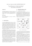
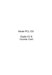
Figure 1-1. AT91 ISP Framework Architecture
Command Line Tool
SAM-PROG
SAM-BA GUI
Customer ISP
TCL-SH
AT91Boot_DLL.dll
AT91Boot_TCL.dll
CAN Dongle dll
ATM6124.sys
JLinkARM.dll
COM Port driver
USB
SAM-ICE
or
JLINK
COM
Driver
CAN
JTAG
(Peak, IXXAT)
1.2
DLL
Prerequisites
! Runs under Windows® 2000/XP
! A SAM-ICE or a JLink JTAG box and its associated USB drivers (only necessary to
use JTAG communication link)
! CAN Dongles
– PCAN-USB Peak dongle
– USB-to-CAN compact IXXAT dongle
! TCL Toolchain including tclsh can be downloaded from the following URL:
http://www.activestate.com/Products/ActiveTcl/
1-2
6224D–ATARM–28-Jul-06
AT91 In-system Programmer (ISP) User Guide
Introduction
1.3
Installation
1.3.1
Contents
1.3.1.1
Library Directory
Installation is automatic using the AT91_ISP.exe install program.
All files located in the Library directory are necessary for the AT91Boot_DLL to run
correctly.
! AT91Boot_DLL.dll
! AT91Boot_DLL.tlb type library file
! JLinkARM.dll
! AT91Boot_TCL.dll
! CAN Dongle dlls
1.3.1.2
Examples Directory
This directory contains some example projects using AT91Boot_DLL.dll. See the section “Using AT91Boot_DLL Project Examples” for more information on the following
projects:
! OLE_MFC project under Visual C++ 6.0
! OLE_without_MFC project under Visual C++ 6.0
! CAN_TCLSH gives an example of a TCL script that can be used to program a
SAM7X256-based board over the CAN network.
1.3.1.3
SAM-PROG
Application
This application downloads a binary file into the Flash memory of one or more
AT91SAM devices in parallel from a PC or JTAG probe.
1.3.1.4
SAM-BA Boot4CAN
Directory
This directory contains binary files for AT91SAM7A3 and AT91SAM7X devices. These
files must be programmed into internal Flash memory before communicating over a
CAN. SAM-PROG can be used to program these files.
1.3.2
DLL Registration
AT91Boot_DLL needs to be registered in the Windows Base Register in order to be
used correctly. The Install program will register AT91Boot_DLL automatically.
AT91Boot_DLL.dll uses JLinkARM dll. In order for the user to compile a project anywhere, “YOUR_INSTALL_DIRECTORY\Library” path has been added to the PATH user
environment variable. If it is not the case, JLinkARM dlls has to be set in the current
directory of your application in order to be found by the AT91Boot_DLL.
Note: It is also possible to copy dll contained in the Library directory into
WINNT/System32 as this directory is in the PATH environment variable by
default. Do not forget to register AT91Boot_DLL after moving.
To register AT91Boot_DLL manually, execute the following command from a DOS Window or directly through the Windows Start/Execute menu:
regsvr32 /s /c “YOUR_INSTALL_DIRECTORY\AT91Boot_DLL.dll“
Note:
1.3.3
Updating
JLink/SAM-ICE
Software
regsvr32.exe is located in WINNT/System32 directory
In order to function correctly, compatibility between JLink/SAM-ICE firmware, USB drivers and JLinkARM DLL is necessary. Thus it is recommended to update JLink/SAM-ICE
software.
The JLink/SAM-ICE software update, contained in a zip file, is available on the
www.segger.com web site in the “Downloads”, then “J-Link ARM” sub-areas. To proceed with update, carry out the following steps:
! Download the “Jlink_ARM” zip file.
AT91 In-system Programmer (ISP) User Guide
1-3
6224D–ATARM–28-Jul-06
Introduction
! Unzip this download.
! Run the .exe file contained in it.
! Check the update in the “Doc\ReleaseNotes”.
! Run the new J-Link.exe to update the JLink/SAM-ICE firmware.
! Check if your PC driver is up to date with the delivery driver in the “USBDriver” folder
contained in the .exe.
! Copy the JLinkARM.dll DLL to “YOUR_INSTALL_DIRECTORY\Library\” folder.
This completes the software update.
1-4
6224D–ATARM–28-Jul-06
AT91 In-system Programmer (ISP) User Guide
Section 2
Communicating with AT91SAM
Devices
2.1
Communication
Links
AT91Boot_DLL connects AT91SAM-based targets through a USB link, a serial link or a
JTAG using a SAM-ICE or JLink JTAG box.
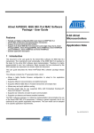
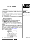
Figure 2-1. Different Ways of Communicating with AT91SAM-based Targets
CAN Link
AT91SAM-based Board
running
SAM-BA Boot4CAN
CAN Dongle
USB Link
Host Debugger
AT91SAM-based Board
running SAM-BA Boot
Serial Link
SAM-ICE/JLink
JTAG Interface
DBGU
AT91SAM-based Board
running SAM-BA Boot
AT91SAM-based Board
JTAG Link
Depending on which communication link is selected, the target must be in the following
state:
! When using the USB link or the DBGU serial link, SAM-BA Boot must run onto the
target.
! When using the CAN link, SAM-BA Boot4CAN must run onto the target.
! When using JTAG communication through SAM-ICE or JLink, the target may be in an
undefined state. In this case, it is up to the user to configure the target (PLL, etc.) if
necessary.
AT91 In-system Programmer (ISP) User Guide
2-1
6224D–ATARM–28-Jul-06
Communicating with AT91SAM Devices
2.2
Starting
Communication
The AT91Boot_DLL principle is simple. It consists of:
1. Scanning all devices connected to the PC
2. Opening communication to the selected device
3. Performing all desired actions such as writing into Flash memory
4. Closing communication
2-2
6224D–ATARM–28-Jul-06
AT91 In-system Programmer (ISP) User Guide
Section 3
AT91Boot_DLL Interface
3.1
3.1.1
Low-level
Functions
A description and a code example is given for each function.
AT91Boot_Scan
This function scans connected devices and returns a list of connected devices. Detection is performed in the following order:
These functions are available for all AT91SAM microcontrollers.
1. USB connected devices using ATM6124.sys driver
2. Connected SAM-ICE or JLink devices
3. CAN dongles (Peak, IXXAT)
4. All available serial COM ports
Note:
3.1.1.1
Description
The AT91Boot_Scan function does not verify if an Atmel® device is really
present, so even if there are no Atmel devices connected to SAM-ICE/JLink
devices, CAN dongles or COM ports, these connections are returned in the connected devices list. This does not concern USB devices.
void AT91Boot_Scan(char *pDevList);
Table 3-1. AT91Boot_Scan
Type
Name
Details
Input Parameters
char *pDevList
Pointer to a char* table.
All table entries must have been allocated prior using
the AT91Boot_Scan function. (1)
Output Parameters
char *pDevList
Strings returned in the table:
- “\usb\ARMX“ for USB connected devices
- “\jlink\ARMX“ for SAM-ICE/JLink connected devices
- “\can\AtCanPeak\ARM“ for PCAN-USB Peak
connected dongle
- “\can\Ixxat\ARM“ for USB-to-CAN compact IXXAT
connected dongle
- “COMX“ for available COM ports
Return Code
none
Note:
1. Each string must be allocated from the application and must have a size superior to
80 bytes. That string is used to recover, in particular CAN dongle, USB or JTAG box
device name which is then replaced by a reduced symbolic name.
AT91 In-system Programmer (ISP) User Guide
3-1
6224D–ATARM–28-Jul-06
AT91Boot_DLL Interface
3.1.1.2
Code Example
CHAR *strConnectedDevices[5];
for (UINT i=0; i<5; i++)
strConnectedDevices[i] = (CHAR *)malloc(100);
AT91Boot_Scan((char *)strConnectedDevices);
AT91Boot_Scan may return code similar to that below:
strConnectedDevices[0] : \usb\ARM0
strConnectedDevices[1] : \usb\ARM1
strConnectedDevices[2] : \jlink\ARM0
strConnectedDevices[3] : \can\AtCanPeak\ARM
strConnectedDevices[4] : COM1
3.1.2
AT91Boot_Open
This function opens the communication link on an AT91SAM device depending on the
string given in the argument:
! USB
! JTAG
! CAN
! Serial COM port
Note: At this step, the Atmel device MUST be connected to either SAM-ICE/JLink,
CAN network or COM port if using such a communication link.
3.1.2.1
Description
void AT91Boot_Open(char *name, int *h_handle);
Table 3-2. AT91Boot_Open
Type
Name
Details
Input Parameters
*name
Pointer to a string returned by AT91Boot_Scan function(1)
Output Parameters
*h_handle
Communication handle:
- NULL if opening connection failed
- Non NULL if opening connection succeeded
Return Code
void
Note:
3.1.2.2
Code Example
1. As AT91Boot_Scan function detects only CAN dongles and not AT91SAM devices
which are connected to, it is recommended to add an identifier to the end of string for
each
device
such
as,
for
example,
“\can\AtCanPeak\ARM0“,
“\can\AtCanPeak\ARM1“...
AT91Boot_Open(strConnectedDevices[0], &h_handle);
AT91Boot_Open(‘’\can\AtCanPeak\ARM0’’, &h_handle);
3.1.2.3
JTAG
When opening a JTAG communication link through a SAM-ICE or a JLink by using the
Communication Link following command:
AT91Boot_Open(‘’\jlink\ARM0’’, &h_handle);
the following steps are performed:
1. Open JLinkARM.dll and its associated library functions.
2. Set JTAG speed to 30 kHz in order to connect to the target even if it is running at
32 kHz.
3. Stop the target.
3-2
6224D–ATARM–28-Jul-06
AT91 In-system Programmer (ISP) User Guide
AT91Boot_DLL Interface
4. Set a hardware breakpoint at address 0.
5. Send a PROCRST command (RSTC_CR) in the Reset Controller in order to disable the Watchdog.
6. Wait for the target to reach the breakpoint.
7. Download a monitor into the target internal SRAM that allows communication
only through the ARM Debug Communication Channels(1) by using the SAM-BA
Boot commands(2).
8. Jump to the monitor in internal SRAM. If the target was running at 32kHz, the
monitor switches on the Main Oscillator(3).
9. Set JTAG speed to 3 MHz as it is the lowest allowed crystal frequency.
Note:
1. For further information about DCC, visit www.arm.com.
2. For further informations about SAM-BA Boot commands, see the Boot Program section of the product datasheet.
3. It is recommended to configure the PLL when returning from AT91Boot_Open function in order to speed up monitor execution.
3.1.3
AT91Boot_Close
This function closes the communication link previously opened on an AT91SAM device.
3.1.3.1
Description
void AT91Boot_Close(int h_handle);
Table 3-3. AT91Boot_Close
3.1.3.2
Code Example
Type
Name
Details
Input Parameters
h_handle
Communication handle returned by AT91Boot_Open
function
Output Parameters
none
Return Code
void
AT91Boot_Close(h_handle);
AT91 In-system Programmer (ISP) User Guide
3-3
6224D–ATARM–28-Jul-06
AT91Boot_DLL Interface
3.1.4
AT91Boot_CAN_Configure
This function configures the target as well as AT91Boot_DLL initialization.
It allows:
! Configuring CAN network baudrate (Set Baudrate action). It is always the first action
to perform after calling AT91Boot_Open function. It opens CAN dongles dlls with
correct baudrate parameter. Only baudrate value passed in uValue parameter is
necessary for such an action. uParam parameter can be null.
! Connecting/Disconnecting Target. It is necessary to connect to the target after a Set
Baudrate action and before trying to communicate. Both uParam and uValue
parameters can be null.
! Reading/writing CAN configuration bytes on the target. See the document “AT91SAM
CAN Bootloader”, Lit. No. 6220 for more information.
Note: See Examples/CAN_TCLSH/test.tcl script for more information on how to use
this function.
3.1.4.1
Prerequisite
3-4
6224D–ATARM–28-Jul-06
As these parameters are stored into internal Flash memory, the Embedded Flash Controller Flash Mode Register (EFC_FMR) must be programmed correctly before using
this function.
Note: AT91SAM CAN Bootloader automatically switches on the Main Oscillator when
starting.
AT91 In-system Programmer (ISP) User Guide
AT91Boot_DLL Interface
3.1.4.2
Description
AT91Boot_CAN_Configure
(int h_handle, int uAction, int uParam, int *uValue, int err_code);
Table 3-4. AT91Boot_CAN_Configure
Type
Name
Details
h_handle
Communication handle returned by AT91Boot_Open
function
uAction
Select Read or Write Action
•
0x00 corresponds to a Read action
•
0x01 corresponds to a Write action
•
0x03 corresponds to a Set Baudrate action
•
0x04 corresponds to a Connect Target action
•
0x05 corresponds to a Disconnect Target action
uParam
Select Parameters to Read/Write
•
0x00 = Node Number (NNB)
•
0x01 = CAN Re-locatable Identifier Segment (CRIS)
•
0x02 = AutoBaud Mode (ABM)
•
0x03 = Propagation Segment (PROPAG_SEG)
•
0x04 = Phase Segment 1 (PHASE1_SEG)
•
0x05 = Phase Segment 2 (PHASE2_SEG)
•
0x06 = Baudrate Prescaler (BRP)
Input Parameters
Byte to write if uAction corresponds to a Write
*uValue
Output Parameters
*uValue
If uAction corresponds to a Set Baudrate action, it is used
only as CAN baudrate parameter for CAN baudrate
configuration.
The different configuration values are:
•
100 (k)
•
125 (k)
•
250 (k)
•
500 (k)
•
1000 (k) (default value if no configuration passed)
Byte to read if uAction corresponds to a Read
•
*err_code
Return Code
AT91 In-system Programmer (ISP) User Guide
(int)(0x0000) AT91C_BOOT_DLL_OK
CAN Error Codes:
•
(int )(0x8001): CAN_Open dll function returned “fail”
•
(int )(0x8002): CAN_Read dll function returned “fail”
•
(int )(0x8003): CAN_Write dll function returned “fail”
•
(int )(0x8004): Target not disconnected
•
(int )(0x8005): Target not connected
•
(int )(0x8006): uAction parameter is not valid
void
3-5
6224D–ATARM–28-Jul-06
AT91Boot_DLL Interface
3.1.4.3
Code Example
#define CAN_WRITE_CFG 1
#define CAN_SET_BAUDRATE 3
#define CAN_CONNECT_TARGET 4
#define CAN_DISCONNECT_TARGET 5
#define CAN_NNB 0
int err_code;
// First Set CAN Baudrate
int baudrate = 500;
AT91Boot_CAN_Configure(h_handle, CAN_SET_BAUDRATE, 0, &baudrate, &err_code);
// Then Connect to target
AT91Boot_CAN_Configure(h_handle, CAN_CONNECT_TARGET, 0, NULL, &err_code);
// DO NOT FORGET TO CONFIGURE EFC_FMR REGISTER CORRECTLY
AT91Boot_Write_Int(h_handle, 0xXXXXXXXX , 0xFFFFFF60, &err_code);
// Write a new Node Number value, for example...
int new_nnb = 0x10;
AT91Boot_CAN_Configure(h_handle, CAN_WRITE_CFG, CAN_NNB, &new_nnb,
&err_code);
// Disconnect the target
AT91Boot_CAN_Configure(h_handle, CAN_DISCONNECT_TARGET, 0, NULL, &err_code);
3-6
6224D–ATARM–28-Jul-06
AT91 In-system Programmer (ISP) User Guide
AT91Boot_DLL Interface
3.1.5
AT91Boot_Write_Int
This function writes a 32-bit word into the volatile memory of the connected target.
3.1.5.1
Description
void AT91Boot_Write_Int(int h_handle, int uValue, int uAddress, int *err_code);
Table 3-5. AT91Boot_Write_Int
Type
Input Parameters
Output Parameters
Name
Details
h_handle
Communication handle returned by AT91Boot_Open
function
uValue
32-bit value to write
uAddress
Address where to write 32-bit value
none
•
Error Code
*err_code
(int)(0x0000) AT91C_BOOT_DLL_OK
Standard Error Codes:
•
(int )(0xF001): Bad h_handle parameter
•
(int )(0xF002): Address is not correctly aligned
•
(int )(0xF005): Communication link broken
CAN Error Codes:
•
(int )(0x8002): CAN_Read dll function returned “fail”
•
(int )(0x8003): CAN_Write dll function returned “fail”
Return Code
3.1.5.2
Code Example
void
AT91Boot_Write_Int(h_handle, 0xCAFECAFE, 0x200000, &err_code);
AT91 In-system Programmer (ISP) User Guide
3-7
6224D–ATARM–28-Jul-06
AT91Boot_DLL Interface
3.1.6
AT91Boot_Write_Short This function writes a 16-bit word into the volatile memory of the connected target.
3.1.6.1
Description
void AT91Boot_Write_Short(int h_handle, short wValue, int uAddress, int *err_code);
Table 3-6. AT91Boot_Write_Short
Type
Name
Details
h_handle
Communication handle returned by AT91Boot_Open
function
wValue
16-bit value to write
Input Parameters
uAddress
Address where to write 16-bit value
Output Parameters
none
•
Error Code
*err_code
(int)(0x0000) AT91C_BOOT_DLL_OK
Standard Error Codes:
•
(int )(0xF001): Bad h_handle parameter
•
(int )(0xF002): Address is not correctly aligned
•
(int )(0xF005): Communication link broken
CAN Error Codes:
•
(int )(0x8002): CAN_Read dll function returned “fail”
•
(int )(0x8003): CAN_Write dll function returned “fail”
Return Code
void
3.1.6.2
Code Example
3.1.7
AT91Boot_Write_Byte This function writes an 8-bit word into the volatile memory of the connected target.
3.1.7.1
Description
AT91Boot_Write_Short(h_handle, 0xCAFE, 0x200000, &err_code);
void AT91Boot_Write_Byte(int h_handle, char bValue, int uAddress, int *err_code);
Table 3-7. AT91Boot_Write_Byte
Type
Input Parameters
3-8
6224D–ATARM–28-Jul-06
Name
Details
h_handle
Communication handle returned by AT91Boot_Open
function
bValue
8-bit value to write
uAddress
Address where to write 8-bit value
AT91 In-system Programmer (ISP) User Guide
AT91Boot_DLL Interface
Table 3-7. AT91Boot_Write_Byte
Type
Name
Output Parameters
none
Details
•
Error Code
*err_code
(int)(0x0000) AT91C_BOOT_DLL_OK
Standard Error Codes:
•
(int )(0xF001): Bad h_handle parameter
•
(int )(0xF002): Address is not correctly aligned
•
(int )(0xF005): Communication link broken
CAN Error Codes:
•
(int )(0x8002): CAN_Read dll function returned “fail”
•
(int )(0x8003): CAN_Write dll function returned “fail”
Return Code
void
3.1.7.2
Code Example
3.1.8
AT91Boot_Write_Data This function writes X bytes into the volatile memory of the connected target.
3.1.8.1
Description
AT91Boot_Write_Byte(h_handle, 0xFE, 0x200000, &err_code);
void AT91Boot_Write_Data(int h_handle, int uAddress, char *bValue, int uSize, int
*err_code);
Table 3-8. AT91Boot_Write_Data
Type
Input Parameters
Output Parameters
Name
Details
h_handle
Communication handle returned by AT91Boot_Open
function
uAddress
Address where to write 8-bit value
*bValue
Pointer to 8-bit data buffer to write
uSize
Buffer size in bytes
none
•
Error Code
*err_code
(int)(0x0000) AT91C_BOOT_DLL_OK
Standard Error Codes:
•
(int )(0xF001): Bad h_handle parameter
•
(int )(0xF004): USART Communication link not opened
•
(int )(0xF005): Communication link broken
CAN Error Codes:
•
(int )(0x8002): CAN_Read dll function returned “fail”
•
(int )(0x8003): CAN_Write dll function returned “fail”
Return Code
3.1.8.2
Code Example
void
char bData[10] =
{0x00, 0x01, 0x02, 0x03, 0x04, 0x05, 0x06, 0x07, 0x08, 0x09};
AT91Boot_Write_Data(h_handle, 0x200000, bData, 10, &err_code);
AT91 In-system Programmer (ISP) User Guide
3-9
6224D–ATARM–28-Jul-06
AT91Boot_DLL Interface
3.1.9
AT91Boot_Read_Int
This function reads a 32-bit word from the connected target.
3.1.9.1
Description
void AT91Boot_Read_Int(int h_handle, int *uValue, int uAddress, int *err_code);
Table 3-9. AT91Boot_Read_Int
Type
Input Parameters
Output Parameters
Name
Details
h_handle
Communication handle returned by AT91Boot_Open
function
*uValue
Pointer to a 32-bit value
uAddress
Address where to read 32-bit value
*uValue
32-bit read value
•
Error Code
*err_code
(int)(0x0000) AT91C_BOOT_DLL_OK
Standard Error Codes:
•
(int )(0xF001): Bad h_handle parameter
•
(int )(0xF002): Address is not correctly aligned
•
(int )(0xF005): Communication link broken
CAN Error Codes:
•
(int )(0x8002): CAN_Read dll function returned “fail”
•
(int )(0x8003): CAN_Write dll function returned “fail”
Return Code
3.1.9.2
Code Example
void
int ChipId;
AT91Boot_Read_Int(h_handle, &ChipId, 0xFFFFF240, &err_code);
3.1.10
AT91Boot_Read_Short This function reads a 16-bit word from the connected target.
3.1.10.1 Description
void AT91Boot_Read_Short(int h_handle, short *wValue, int uAddress, int *err_code);
Table 3-10. AT91Boot_Read_Short
Type
Input Parameters
3-10
6224D–ATARM–28-Jul-06
Name
Details
h_handle
Communication handle returned by AT91Boot_Open
function
*wValue
Pointer to a 16-bit value
uAddress
Address where to read 16-bit value
AT91 In-system Programmer (ISP) User Guide
AT91Boot_DLL Interface
Table 3-10. AT91Boot_Read_Short
Type
Name
Details
Output Parameters
*wValue
16-bit read value
•
Error Code
*err_code
(int)(0x0000) AT91C_BOOT_DLL_OK
Standard Error Codes:
•
(int )(0xF001): Bad h_handle parameter
•
(int )(0xF002): Address is not correctly aligned
•
(int )(0xF005): Communication link broken
CAN Error Codes:
•
(int )(0x8002): CAN_Read dll function returned “fail”
•
(int )(0x8003): CAN_Write dll function returned “fail”
Return Code
3.1.10.2 Code Example
void
short wRead;
AT91Boot_Read_Short(h_handle, &wRead, 0x200000, &err_code);
AT91 In-system Programmer (ISP) User Guide
3-11
6224D–ATARM–28-Jul-06
AT91Boot_DLL Interface
3.1.11
AT91Boot_Read_Byte This function reads an 8-bit word from the connected target.
3.1.11.1 Description
void AT91Boot_Read_Byte(int h_handle, char *bValue, int uAddress, int *err_code);
Table 3-11. AT91Boot_Read_Byte
Type
Input Parameters
Output Parameters
Name
Details
h_handle
Communication handle returned by AT91Boot_Open
function
*bValue
Pointer to an 8-bit value
uAddress
Address where to read 16-bit value
*bValue
8-bit read value
•
Error Code
*err_code
(int)(0x0000) AT91C_BOOT_DLL_OK
Standard Error Codes:
•
(int )(0xF001): Bad h_handle parameter
•
(int )(0xF002): Address is not correctly aligned
•
(int )(0xF005): Communication link broken
CAN Error Codes:
•
(int )(0x8002): CAN_Read dll function returned “fail”
•
(int )(0x8003): CAN_Write dll function returned “fail”
Return Code
3.1.11.2 Code Example
void
char bRead;
AT91Boot_Read_Byte(h_handle, &bRead, 0x200000, &err_code);
3.1.12
AT91Boot_Read_Data This function reads X bytes from the connected target.
3.1.12.1 Description
void AT91Boot_Read_Data(int h_handle, int uAddress, char *bValue, int uSize, int
*err_code);
Table 3-12. AT91Boot_Read_Data
Type
Input Parameters
3-12
6224D–ATARM–28-Jul-06
Name
Details
h_handle
Communication handle returned by AT91Boot_Open
function
uAddress
Address where to read 8-bit data
*bValue
Pointer to an 8-bit data buffer where to store read data
uSize
Number of bytes to read
AT91 In-system Programmer (ISP) User Guide
AT91Boot_DLL Interface
Table 3-12. AT91Boot_Read_Data
Type
Name
Details
Output Parameters
*bValue
Pointer to read data
•
Error Code
*err_code
(int)(0x0000) AT91C_BOOT_DLL_OK
Standard Error Codes:
•
(int )(0xF001): Bad h_handle parameter
•
(int )(0xF004): USART Communication link not opened
•
(int )(0xF005): Communication link broken
CAN Error Codes:
•
(int )(0x8002): CAN_Read dll function returned “fail”
•
(int )(0x8003): CAN_Write dll function returned “fail”
Return Code
3.1.12.2 Code Example
void
char bData[10];
AT91Boot_Read_Data(h_handle, 0x200000, bData, 10, &err_code);
AT91 In-system Programmer (ISP) User Guide
3-13
6224D–ATARM–28-Jul-06
AT91Boot_DLL Interface
3.1.13
AT91Boot_Go
3.1.13.1 Description
This function allows starting code execution at specified address.
void AT91Boot_Go(int h_handle, int uAddress, int *err_code);
Table 3-13. AT91Boot_Read_Data
Type
Name
Details
h_handle
Communication handle returned by AT91Boot_Open
function
uAddress
Address where to start code execution
Input Parameters
Output Parameters
none
•
Error Code
*err_code
(int)(0x0000) AT91C_BOOT_DLL_OK
Standard Error Codes:
•
(int )(0xF001): Bad h_handle parameter
•
(int )(0xF005): Communication link broken
CAN Error Codes:
•
(int )(0x8002): CAN_Read dll function returned “fail”
•
(int )(0x8003): CAN_Write dll function returned “fail”
Return Code
3.1.13.2 Code Example
3-14
6224D–ATARM–28-Jul-06
void
AT91Boot_Go(h_handle, 0x200000, &err_code);
AT91 In-system Programmer (ISP) User Guide
AT91Boot_DLL Interface
3.2
Internal Flash
Programming
Functions
3.2.1
AT91Boot_SAM7xxx_Send_Flash
These functions are available only for AT91SAM microcontrollers with Flash.
These functions make it possible to write X bytes into the internal Flash memory of the
connected target. If some sectors are locked, they are unlocked in order to effectively
program the internal Flash memory.
Available functions are:
! AT91Boot_SAM7S32_Send_Flash (available for SAM7S32 and SAM7S321 parts)
! AT91Boot_SAM7S64_Send_Flash
! AT91Boot_SAM7S128_Send_Flash
! AT91Boot_SAM7S256_Send_Flash
! AT91Boot_SAM7S512_Send_Flash
! AT91Boot_SAM7A3_Send_Flash
! AT91Boot_SAM7X128_Send_Flash (available for SAM7X128 and SAM7XC128
parts)
! AT91Boot_SAM7X256_Send_Flash (available for SAM7X256 and SAM7XC256
parts)
! AT91Boot_SAM7X512_Send_Flash (available for SAM7X512 and SAM7XC512
parts)
! AT91Boot_SAM7SE256_Send_Flash
! AT91Boot_SAM7SE512_Send_Flash
3.2.1.1
Prerequisite
Embedded Flash Controller Flash Mode Register (EFC_FMR) must be programmed
correctly prior using one of these functions.
Note:
3.2.1.2
Description
Two Embedded Flash Controllers are embedded in AT91SAM7S512, AT91SAM7X512
and AT91SAM7SE512 parts. Both EFC_FMRx registers must be programmed correctly
prior using one of these functions.
void AT91Boot_SAM7xxx_Send_Flash(int h_handle, int uOffset, char *bData, int uSize,
int *err_code);
Table 3-14. AT91Boot_SAM7xxx_Send_Flash
Type
Input Parameters
AT91 In-system Programmer (ISP) User Guide
Name
Details
h_handle
Communication handle returned by AT91Boot_Open
function
uOffset
Internal Flash Offset where to write 8-bit value
*bData
Pointer to 8-bit data buffer to write
uSize
Buffer size in bytes
3-15
6224D–ATARM–28-Jul-06
AT91Boot_DLL Interface
Table 3-14. AT91Boot_SAM7xxx_Send_Flash
Type
Name
Output Parameters
none
Details
•
Error Code
*err_code
(int)(0x0000) AT91C_BOOT_DLL_OK
Standard Error Codes:
•
(int )(0xF001): Bad h_handle parameter
•
(int )(0xF002): Address is not correctly aligned
•
(int )(0xF003): uSize is not correct
•
(int )(0xF004): USART Communication link not opened
•
(int )(0xF005): Communication link broken
CAN Error Codes:
•
(int )(0x8002): CAN_Read dll function returned “fail”
•
(int )(0x8003): CAN_Write dll function returned “fail”
Return Code
3.2.1.3
Code Example
void
char bData[10] =
{0x00, 0x01, 0x02, 0x03, 0x04, 0x05, 0x06, 0x07, 0x08, 0x09};
// Write buffer at offset 0x100 into internal SAM7S64 Flash
AT91Boot_SAM7S64_Send_Flash(h_handle, 0x100, bData, 10, &err_code);
3-16
6224D–ATARM–28-Jul-06
AT91 In-system Programmer (ISP) User Guide
Section 4
AT91Boot_TCL Interface
Only the prototypes are defined in this chapter. A TCL script example called test.tcl is
given in the Example/CAN_TCLSH directory.
4.1
Loading
AT91Boot_TCL
Functions
AT91Boot_TCL.dll must be loaded in order to access its functions. The command is:
load [file join AT91Boot_TCL.dll] At91boot_tcl
Note:
4.2
Low-level
Functions
The command is case sensitive.
These functions are available for all AT91SAM microcontrollers.
! list TCL_Scan
! set h_handle [TCL_Open $name]
! TCL_Close $h_handle
! TCL_Write_Int $h_handle $uValue $wAddress err_code
! TCL_Write_Short $h_handle $wValue $wAddress err_code
! TCL_Write_Byte $h_handle $bValue $wAddress err_code
! TCL_Write_Data $h_handle, $wAddress $bValue $size err_code
! set uValue [TCL_Read_Int $h_handle $wAddress err_code]
! set wValue [TCL_Read_Short $h_handle $wAddress err_code]
! set bValue [TCL_Read_Byte $h_handle $wAddress err_code]
! set bValue TCL_Read_Data $h_handle $wAddress $size err_code
! TCL_Go $h_handle $wAddress err_code
For Read actions:
! set uValue TCL_CAN_Configure $h_handle $uAction $uParam err_code
For other actions:
AT91 In-system Programmer (ISP) User Guide
4-1
6224D–ATARM–28-Jul-06
AT91Boot_TCL Interface
! TCL_CAN_Configure $h_handle $uAction $uParam $uValue err_code
4.3
Internal Flash
Programming
Functions
These functions are available only for AT91SAM microcontrollers with Flash.
! TCL_SAM7S32_Send_Flash $h_handle $wOffset $bValue $size err_code
! TCL_SAM7S64_Send_Flash $h_handle $wOffset $bValue $size err_code
! TCL_SAM7S128_Send_Flash $h_handle $wOffset $bValue $size err_code
! TCL_SAM7S256_Send_Flash $h_handle $wOffset $bValue $size err_code
! TCL_SAM7S512_Send_Flash $h_handle $wOffset $bValue $size err_code
! TCL_SAM7SA3_Send_Flash $h_handle $wOffset $bValue $size err_code
! TCL_SAM7X128_Send_Flash $h_handle $wOffset $bValue $size err_code
! TCL_SAM7X256_Send_Flash $h_handle $wOffset $bValue $size err_code
! TCL_SAM7X512_Send_Flash $h_handle $wOffset $bValue $size err_code
! TCL_SAM7SE256_Send_Flash $h_handle $wOffset $bValue $size err_code
! TCL_SAM7SE512_Send_Flash $h_handle $wOffset $bValue $size err_code
4.4
TCL Script
Example
The following script gives an example of how to program a binary file into a SAM7S64
internal Flash. See Section 5.2 for details on how to run the script.
load [file join ../../Library/AT91Boot_TCL.dll] At91boot_tcl
set DevList(0) ""
set err_code 0
# SCAN connected devices
set i 0
foreach {name} [TCL_Scan] {
set DevList($i) $name
puts "DevList($i): $DevList($i)"
incr i 1
}
# Open first one in the list
set h_handle 0
set i 0
set h_handle [TCL_Open $DevList($i)]
# TRY FLASH application.bin file into SAM7S64 internal flash
variable fileName "application.bin"
variable fileAddr 0x0
global valueOfDataForSendFile
# Open and read binary file
set f [open $fileName r]
fconfigure $f -translation binary
set size [file size $fileName]
set valueOfDataForSendFile [read $f $size]
close $f
4-2
6224D–ATARM–28-Jul-06
AT91 In-system Programmer (ISP) User Guide
AT91Boot_TCL Interface
# Write file into Flash
TCL_SAM7S64_Send_Flash $h_handle $fileAddr valueOfDataForSendFile $size
err_code
set valueOfDataForSendFile 0
# Close connection
TCL_Close $h_handle
AT91 In-system Programmer (ISP) User Guide
4-3
6224D–ATARM–28-Jul-06
AT91Boot_TCL Interface
4-4
6224D–ATARM–28-Jul-06
AT91 In-system Programmer (ISP) User Guide
Section 5
Using AT91Boot_DLL Project
Examples
5.1
Visual C++ 6.0
Projects
5.1.1
Using
AT91Boot_DLL with
MFC
The project OLE_MFC.dsw is located in Examples\OLE_MFC folder. It scans connected
devices, opens the first one, reads DBUG chip ID. If an AT91SAM7S256 is detected, it
programs a small application (BasicMouse) in the internal Flash.
To use AT91Boot_DLL in such a project, the following steps must be performed:
! Create an AT91Boot_DLL class in your project. To do this, copy both at91boot_dll.cpp
and at91boot_dll.h files into your project directory.
Note: Do not use the ClassWizard/Add Class/From a type library... as there is a bug in
Visual C++ 6.0. The bug prevents any functions containing a char variable as a
parameter from being imported.
! Initialize OLE libraries by calling AfxOleInit function.
! Create an AT91Boot_DLL driver object to manage AT91Boot_DLL COM object.
! Create an AT91Boot_DLL COM object instance with the AT91Boot_DLL program
ID(1)("AT91Boot_DLL.AT91BootDLL.1") by using CreateDispatch function.
Note:
1. Program ID is stored in the base register and is an easier way to retrieve
AT91Boot_DLL Class ID necessary for CreateDispatch function.
Once these four steps have been performed, DLL functions should be available. See
their prototypes in at91boot_dll.h header file and for details on how to call these
functions.
Note: At this step, if AT91Boot_DLL functions are not available, it is because the
AT91Boot_DLL dll has not been registered correctly. See Section 1.3.2 for
more information.
AT91 In-system Programmer (ISP) User Guide
5-1
6224D–ATARM–28-Jul-06
Using AT91Boot_DLL Project Examples
5.1.1.1
Code Example
#include "at91boot_dll.h"
IAT91BootDLL *m_pAT91BootDLL;
AfxOleInit();
m_pAT91BootDLL = new IAT91BootDLL;
m_pAT91BootDLL->CreateDispatch(_T("AT91Boot_DLL.AT91BootDLL.1"));
5.1.2
Using
AT91Boot_DLL
without MFC
This paragraph explains the project OpenRDI_OLE.dsw located in AT91Boot DLL
Example\OLE without MFC folder.
To use AT91Boot_DLL in such a project, the following steps must be performed:
! Initialize COM library by calling CoInitialize(NULL). Use CoUninitialize() to
close COM Library at the end of the project.
! Import AT91Boot_DLL COM object from AT91Boot_DLL.tlb Type Library file.
Eventually rename namespace if necessary.
! Add using namespace directive to share the same namespace as AT91Boot_DLL
library.
! Create a pointer to AT91Boot_DLL COM object
5.1.2.1
Code Example
In stdafx.h header file
#import "YOUR_INSTALL_DIRECTORY/AT91Boot_DLL.tlb" rename_namespace
("AT91BOOTDLL_Lib")
In OpenRDI_OLE.cpp source file
using namespace AT91BOOTDLL_Lib;
CoInitialize(NULL);
// COM Object Creation
IAT91BootDLLPtr pAT91BootDLL(__uuidof(AT91BootDLL));
5.2
Running the TCL To run this example, TCL Toolchain including tclsh must be downloaded from the URL:
http://www.activestate.com/Products/ActiveTcl/
Script Example
A TCL script example (test.tcl) is given in the Examples/CAN_TCLSH directory. It also
gives an example on how to use AT91Boot_DLL CAN functions. The same principle can
be applied in a Visual C++ project.
The script communicates with an AT91SAM7X256-based board over CAN and programs a USB Mouse application into the internal Flash memory. SAM-BA Boot4CAN is
running. It has been previously programmed in the internal Flash memory with
AT91SAM-PROG application.
First, connect CAN Peak or IXXAT dongle between the PC and the board.
5-2
6224D–ATARM–28-Jul-06
AT91 In-system Programmer (ISP) User Guide
Using AT91Boot_DLL Project Examples
Then, open a DOS window and execute test.tcl script by typing:
tclsh YOUR_INSTALL_DIRECTORY/Examples/CAN TCLSH/test.tcl
After script execution, the USB Mouse application must be programmed.
AT91 In-system Programmer (ISP) User Guide
5-3
6224D–ATARM–28-Jul-06
Using AT91Boot_DLL Project Examples
5-4
6224D–ATARM–28-Jul-06
AT91 In-system Programmer (ISP) User Guide
Section 6
Revision History
Table 6-1. Revision History
Document Ref.
Comments
6224A
First issue.
6224B
Added Section 1.3.3, “Updating JLink/SAM-ICE Software”.
6224C
Updated document to refer to AT91SAM9 microcontrollers in Section 1.1
”Overview”.
6224D
In Section 3.1.2.3 ”JTAG Communication Link”, on page 3-2, added steps 4,
5 and 6.
In “AT91Boot_CAN_Configure”, Section 3.1.4.2 ”Description”, on page 3-5,
updated.
In Section 3.1 ”Low-level Functions”, in Table 3-4 to Table 3-12 added new
information on Error Code. Added new code in all sections “Code Example”.
In Section 3.2 ”Internal Flash Programming Functions”,
“AT91Boot_SAM7xxx_Send_Flash”, updated list of available functions,
Section 3.2.1.1 ”Prerequisite”, added Error Code information to Table 3-14
and updated Section 3.2.1.3 ”Code Example”.
In “AT91Boot_TCL Interface” in Section 4.2 ”Low-level Functions” and in
Section 4.3 ”Internal Flash Programming Functions” updated list of functions.
Updated Section 4.4 ”TCL Script Example”.
AT91 In-system Programmer (ISP) User Guide
Change Request Ref.
2833
6-1
6224D–ATARM–28-Jul-06
Revision History
6-2
6224D–ATARM–28-Jul-06
AT91 In-system Programmer (ISP) User Guide
Atmel Corporation
2325 Orchard Parkway
San Jose, CA 95131, USA
Tel: 1(408) 441-0311
Fax: 1(408) 487-2600
Regional Headquarters
Europe
Atmel Sarl
Route des Arsenaux 41
Case Postale 80
CH-1705 Fribourg
Switzerland
Tel: (41) 26-426-5555
Fax: (41) 26-426-5500
Asia
Room 1219
Chinachem Golden Plaza
77 Mody Road Tsimshatsui
East Kowloon
Hong Kong
Tel: (852) 2721-9778
Fax: (852) 2722-1369
Japan
9F, Tonetsu Shinkawa Bldg.
1-24-8 Shinkawa
Chuo-ku, Tokyo 104-0033
Japan
Tel: (81) 3-3523-3551
Fax: (81) 3-3523-7581
Atmel Operations
Memory
RF/Automotive
2325 Orchard Parkway
San Jose, CA 95131, USA
Tel: 1(408) 441-0311
Fax: 1(408) 436-4314
Theresienstrasse 2
Postfach 3535
74025 Heilbronn, Germany
Tel: (49) 71-31-67-0
Fax: (49) 71-31-67-2340
Microcontrollers
2325 Orchard Parkway
San Jose, CA 95131, USA
Tel: 1(408) 441-0311
Fax: 1(408) 436-4314
La Chantrerie
BP 70602
44306 Nantes Cedex 3, France
Tel: (33) 2-40-18-18-18
Fax: (33) 2-40-18-19-60
ASIC/ASSP/Smart Cards
1150 East Cheyenne Mtn. Blvd.
Colorado Springs, CO 80906, USA
Tel: 1(719) 576-3300
Fax: 1(719) 540-1759
Biometrics/Imaging/Hi-Rel MPU/
High Speed Converters/RF Datacom
Avenue de Rochepleine
BP 123
38521 Saint-Egreve Cedex, France
Tel: (33) 4-76-58-30-00
Fax: (33) 4-76-58-34-80
Zone Industrielle
13106 Rousset Cedex, France
Tel: (33) 4-42-53-60-00
Fax: (33) 4-42-53-60-01
1150 East Cheyenne Mtn. Blvd.
Colorado Springs, CO 80906, USA
Tel: 1(719) 576-3300
Fax: 1(719) 540-1759
Scottish Enterprise Technology Park
Maxwell Building
East Kilbride G75 0QR, Scotland
Tel: (44) 1355-803-000
Fax: (44) 1355-242-743
Literature Requests
www.atmel.com/literature
Disclaimer: The information in this document is provided in connection with Atmel products. No license, express or implied, by estoppel or otherwise, to any
intellectual property right is granted by this document or in connection with the sale of Atmel products. EXCEPT AS SET FORTH IN ATMEL’S TERMS AND CONDITIONS OF SALE LOCATED ON ATMEL’S WEB SITE, ATMEL ASSUMES NO LIABILITY WHATSOEVER AND DISCLAIMS ANY EXPRESS, IMPLIED OR STATUTORY
WARRANTY RELATING TO ITS PRODUCTS INCLUDING, BUT NOT LIMITED TO, THE IMPLIED WARRANTY OF MERCHANTABILITY, FITNESS FOR A PARTICULAR
PURPOSE, OR NON-INFRINGEMENT. IN NO EVENT SHALL ATMEL BE LIABLE FOR ANY DIRECT, INDIRECT, CONSEQUENTIAL, PUNITIVE, SPECIAL OR INCIDENTAL DAMAGES (INCLUDING, WITHOUT LIMITATION, DAMAGES FOR LOSS OF PROFITS, BUSINESS INTERRUPTION, OR LOSS OF INFORMATION) ARISING OUT
OF THE USE OR INABILITY TO USE THIS DOCUMENT, EVEN IF ATMEL HAS BEEN ADVISED OF THE POSSIBILITY OF SUCH DAMAGES. Atmel makes no
representations or warranties with respect to the accuracy or completeness of the contents of this document and reserves the right to make changes to specifications
and product descriptions at any time without notice. Atmel does not make any commitment to update the information contained herein. Unless specifically provided
otherwise, Atmel products are not suitable for, and shall not be used in, automotive applications. Atmel’s products are not intended, authorized, or warranted for use
as components in applications intended to support or sustain life.
© 2006 Atmel Corporation. All rights reserved. Atmel ®, logo and
marks, SAM-BA™ and others are trademarks, of Atmel Corporation
tered trademarks or trademarks of ARM Ltd. Windows ® and others
US and/or other countries. Other terms and product names may be
combinations thereof, Everywhere You Are® and others are registered tradeor its subsidiaries. ARM®, the ARM Powered ® logo and others are the regisare the registered trademarks or trademarks of Microsoft Corporation in the
trademarks of others.
Printed on recycled paper.
6224D–ATARM–28-Jul-06