1
NTAG I2C Explorer Kit
user’s manual
NFC communication
Near Field Communication (NFC) is a short-range, intuitive, wireless connectivity specifically designed and engineered
to provide zero power operation and maximize privacy at very low cost. Because they function as wireless dual-port
memories, NFC connected tags (packaged NFC devices that include a hardwired bus interface) are useful in any
application that can take advantage of data transfer between an embedded system and an external reader/writer
(e.g., an NFC-enabled mobile device). In fact, NFC connected tags enable exciting new capabilities for applications
ranging from home automation to home appliances, health care tracking to utility monitoring, zero power electronic
product configuration to zero effort consumable goods replenishment—the long touted "Internet of Things" actually
come to life, but with greater privacy protection and lower cost than other approaches.
NTAG I2C connected tag chip
The NTAG I2C tag chip, the first connected product of NXP’s NTAG family, offers both contactless (NFC Forum
compliant) and contact (I2C serial bus) interfaces (see Figure 1). If it has an external power supply, or by using its
embedded energy-harvesting feature to power itself, the NTAG I2C device can communicate with a microcontroller or
other I2C-compatible device via its I2C serial bus. The NTAG I2C device contains two memory types:
4 EEPROM memory compliant with the NFC Forum Type 2 Tag implementation
4 64-byte SRAM memory, which is mapped within the EEPROM memory and powered externally
Without an external power supply, the NTAG I2C tag chip can communicate via its RF interface as a passive NFC
tag, and because it contains EEPROM, store data for later retrieval via the I2C serial bus. Under power, the SRAM
memory supports a Pass-Through mode that allows fast download and upload of data from the RF interface to the
I2C interface and vice versa without affecting the EEPROM access limitations, essentially creating a wireless RF to
connected I2C serial bus bridge.
The NTAG I2C device can also use its energy-harvesting feature to supply power to external (low power) devices,
such as microcontrollers, for zero external power operation. A separate, configurable Field Detection pin provides an
external trigger depending on the activities at the RF interface, avoiding processor cycle consuming polling schemes,
and delivering additional application flexibility.
I 2C
EEPROM
1
0
1
0
1
0
Microcontroller
NFC
enabled device
Energy harvesting
Data
Field detection
Energy
Data
Energy
Figure 1 NTAG I2C tag chip contact and contactless interfaces
NXP offers the NTAG I2C product in two different versions: the NTAG I2C 1K version with 888 bytes freely available in
the user memory, and the NTAG I2C 2K version with 1904 bytes freely available in the user memory.
NTAG I2C Explorer Kit contents
To demonstrate the unique properties of the NTAG I2C tag chip, NXP developed the NTAG I2C Explorer Kit, an all-inone demonstration/development resource for NFC connected tag chips. By including a full complement of hardware
and software tools, users can not only investigate the capabilities of the chip through the various demonstrations, but
also develop and test their own applications (with purchase of the optional LPC-Link2 debug probe).
NXP's NTAG I2C Explorer Kit supports interactive demonstrations and enables exploration of all NTAG I2C tag chip
capabilities for both the hardware designer and the application developer.
Optionally, the addition of the LPC-Link2 Debugger probe kit allows easy debugging of code ported directly in the
NTAG I2C Explorer Board, facilitating custom applications.
Table 1 NTAG I2C Explorer Kit components
NTAG I2C Explorer Board
A dual purpose demonstration and development hardware board based on the NXP
LPC 11U24 microcontroller, with onboard LCD display, NXP PCT2075 temperature
sensor, voltage monitors, I2C serial bus connector, and JTAG/SWD debug connector to
demonstrate bi-directional I2C serial bus/NFC communication, illustrate NDEF messaging,
monitor energy harvesting capability, and provide a localized application development
environment
NFC Antennas
NTAG I2C tag chips mounted on a variety of different antenna types (Class 4, 5, and 6
FR4 PCB-based with separate antenna pads for custom antenna use, as well as a Class 6
Flex-board based tag for easier product insertion testing) and with built-in I2C serial bus
interface connectors
NTAG I2C demo
From the Google Play Store, load the Android™ application: “NTAG I2C Demoboard,“ an
interactive demonstration application for NFC-enabled phones
NXP NTAG I2C Explorer Kit user’s manual
2
Table 1 NTAG I2C Explorer Kit components
NTAG I2C packaged samples
Peek and Poke
A PC-based NTAG I2C device register and memory exploration software tool with a
graphical user interface
NFC RF Detector Board
An RF detector with visual (LED) output to facilitate location of the optimum RF field, or to
ensure that NFC has been enabled
NFC USB Reader
PC-based PN544PC NFC reader using the NXP LPC11U24 microcontroller with associated
graphical user interface and USB-micro to USB cable for those without an NFC-enabled
mobile device, where one desires additional performance over the mobile device reader/
writer capability, or for embedded applications
USB/micro USB cable
Optional LPC-Link2 debug probe
The LPC-Link2 debug probe is a low-cost development tool platform for the
LPC MCUs (such as the LPC 11U24) including a target board with integrated
debug probe plus debug ribbon cable, and supported by an Eclipse-based
integrated development environment.
NXP NTAG I2C Explorer Kit user’s manual
3
Contents
NFC communication
1
NTAG I2C Explorer Kit contents
2
1 Definitions
1.1 Nomenclature and acronyms 1.2 Antenna classes defined 1.2.2 “Class 4” antennas 1.2.3 “Class 5” antennas 1.2.4 “Class 6” antennas 5
5
5
5
6
6
2 NXP NTAG I2C Explorer Kit Contents and Setup
7
2.1 Kit contents 7
2.1.1 Kit hardware 7
2.1.1.1 Explorer board 7
2.1.1.2 NFC antennas 8
2.1.1.3 NFC USB Reader board 9
2.1.1.4 NFC RF detector board 10
2.1.1.5 USB to micro USB cable 10
2.1.1.6 LPC-Link2 debug board 10
2.1.2 Kit software 11
2.2 System requirements and setup 11
2.2.1 NFC phone compatibility 11
2.2.2 PC details 12
2.2.3 Enabling NFC on Android device 12
2.2.4 Location of NFC antenna 12
2.2.5 NFC-enabled phone APK 13
2.2.6 NTAG I2C Explorer board firmware load 13
2
2.2.8 Download NTAG I C demo GUI for PC software 14
3 NTAG I2C Demoboard Android phone application
3.1 Splash window 3.2 Default home screens and power harvesting 3.3 LED tab 3.3.1 Configuring board to demonstrate RF to I2C
communication 3.3.2 Reading board input to demonstrate I2C to RF
communication 3.3.3 Temperature sensor 3.4 NDEF tab 3.4.1 Writing NDEF data 3.4.2 Reading NDEF data 3.4.3 Displaying NDEF on the Explorer board LCD 3.5 Speed tab 3.5.1 SRAM board configuration 3.5.2 EEPROM configuration 3.6 Config tab 3.6.1 Reading tag memory 3.6.2 Resetting tag memory NXP NTAG I2C Explorer Kit user’s manual
15
15
15
16
16
17
18
19
19
20
21
21
22
22
23
24
24
3.6.3 Reading session registers 3.6.4 Reading/writing configuration registers 25
26
4 NTAG I2C Explorer Peek and Poke GUI
27
4.1 Peek and Poke GUI software installation 27
4.2 NTAG I2C Explorer Peek and Poke GUI overview 28
4.3 GUI top control bar details 29
4.3.1 Device selection 29
4.3.2 Memory block selection 29
4.3.3 Read and write controls 30
4.3.4 I2C device address and scanning 30
4.3.5 I2C clock frequency 31
4.3.6 Changing NTAG I2C tag chip memory contents 31
4.4 NTAG I2C Explorer lower left screen controls 32
4.4.1 USB data logging 32
4.4.2 Session register 33
4.4.3 Session register details 34
4.4.4 Configuration registers 35
4.4.5 Configuration register details 36
4.4.6 Help screens for session and configuration registers
37
5 USB NFC Reader
38
6 LPC-Link2 debug board
39
7 Summary
39
8 Appendix A: Optimal NFC phone placement 8.1 Using the NFC RF Detector Board 8.2 Selecting an NTAG I2C antenna board The easier case: Samsung Galaxy 5 The more difficult case: HTC 40
40
41
41
42
9 Appendix B: Application processing details
9.1 LED application 9.2 Speed test process 9.2.1 SRAM 9.2.2 EEPROM 44
44
44
44
45
10 References
45
10.1 NTAG I2C datasheet 45
10.2 NXP NTAG Antenna Design Guide Application Note
45
10.3 NDEF 45
10.4 I2C Serial Bus Specification 45
10.5 Microcontrollers 46
11 About NXP
46
12 Legal
47
4
1 Definitions
1.1 Nomenclature and acronyms
For convenience sake, the following shortcut names and acronyms are used in the document:
4Explorer Board: NXP NTAG I2C Explorer Board (see 2.1.1)
4Reader Board: USB-based, PN544 NFC transceiver board (see 2.1.1)
4Peek and Poke: NTAG I²C Explorer Peek and Poke (see 2.1.2)
1.2 Antenna classes defined
The ISO/IEC standard describes six antenna classes (Class 1 through Class 6), which refer to their form factor and size.
For an NFC tag, NXP recommends using “Class 3” through “Class 6.” The following describes these recommended
form factors/sizes. For more information, see the NTAG Antenna Design Guide Application Note (AN11276).
1.2.1 “Class 3” antennas
A “Class 3” antenna shall meet the requirements of being located within a zone defined as (see Figure 2):
4An external rectangle of 50 x 40 mm
4An internal rectangle of 35 x 24 mm, centered in the external rectangle, with 3 mm corner radii
OR
4An external circle with diameter of 50 mm
4An internal circle with diameter of 32 mm, concentric with the external circle
50mm
35mm
24mm
40mm
ø 50mm
ø 32mm
R 3mm
PICC antenna zone
PICC antenna zone
Figure 2 "Class 3" antenna specified zones
1.2.2 “Class 4” antennas
A “Class 4” antenna shall meet the requirements of being located within a zone defined as (see Figure 3):
4An external rectangle of 50 x 27 mm
4An internal rectangle of 35 x 13 mm, centered in the external rectangle, with 3 mm corner radii
OR
4An external circle with diameter of 41 mm
4An internal circle with diameter of 24 mm, concentric with the external circle
NXP NTAG I2C Explorer Kit user’s manual
5
50mm
ø 41mm
13mm
27mm
35mm
ø 24mm
R 3mm
PICC antenna zone
PICC antenna zone
Figure 3 "Class 4" antenna specified zones
1.2.3 “Class 5” antennas
A “Class 5” antenna shall meet the requirements of being located within a zone defined as (see Figure 4):
4An external rectangle of 40.5 x 24.5 mm
4An internal rectangle of 25 x 10 mm, centered in the external rectangle, with 3 mm corner radii
OR
4An external circle with diameter of 35 mm
4An internal circle with diameter of 18 mm, concentric with the external circle
40.5mm
ø 35mm
10mm
24.5mm
25mm
ø 18mm
R 3mm
PICC antenna zone
PICC antenna zone
Figure 4 "Class 5" antenna specified zones
1.2.4 “Class 6” antennas
A “Class 6” antenna shall meet the requirements of being located within a zone defined as either a rectangle of
dimensions 25 x 20 mm, or a circle of 25 mm diameter (see Figure 5).
25mm
20mm
ø 25mm
Figure 5 "Class 6" antenna specified zones
NXP NTAG I2C Explorer Kit user’s manual
6
2 NXP NTAG I2C Explorer Kit Contents and Setup
2.1 Kit contents
The NXP NTAG I2C Explorer is a hardware/software tool developers can use to understand the NXP NTAG I2C tag
chip functionality and demonstrate its potential for other applications. The kit includes:
Table 2. NTAG I2C Explorer Kit contents
Reference
Included
NTAG I2C Explorer development/demo board with Class 4 antenna
2.1.1.1
✔
Additional interchangeable NTAG I2C antennas (PCB and flex)
2.1.1.2
✔
Android mobile app downloadable from Google Playstore
3
✔
Peek & Poke PC-based utility to probe NTAG I2C memory map
4
✔
NTAG I C sample ICs
—
✔
NFC USB Reader with PC user interface
2.1.1.3
✔
NFC RF detector board
2.1.1.4
✔
USB/micro-USB communication cable
2.1.1.5
✔
™
2
Optional purchase
Windows based GUI app for users without an NFC mobile device
™
Optional LPC-LINK2 debug probe plus debug ribbon cable
2.1.1.6
✔
2.1.1 Kit hardware
2.1.1.1 Explorer board
NXP NTAG I2C Explorer board (LCD mounted above a small PCB populated with an NXP LPC11U24 microprocessor,
NTAG I2C tag chip interface connector, JTAG/SWD debug connector, RGB LED, NXP PCT2075 temperature sensor,
micro USB connector, and five push button controls).
JTAG/SWD
connector
NTAG I2C
connection
MicroUSB
RGB LED
Temperature
sensor
Red
control
Green
control
Blue
control
Reset
ISP
Figure 6 Explorer Board components
NXP NTAG I2C Explorer Kit user’s manual
7
2.1.1.2 NFC antennas
Class 4 antenna: Class 4 FR4 antenna board — NTAG I2C integrated circuit (IC) mounted with a Class 4 NFC antenna
and a connector for the NTAG I2C IC connections of:
4FD: Field Detect
4Vout: Power harvesting output
4SCL: I2C bus clock line
4 SDA: I2C bus data line
4 VSS: Ground
4 VCC: Power
NTAG I2C
tag chip
NFC antenna
structure
Figure 7 Class 4 antenna board
Class 5 antenna: Class 5 FR4 antenna board (same as Class 4 board, except with a Class 5 antenna structure). Note
also the additional connection pads near the NTAG I2C chip. These pads may be used to connect a custom antenna,
if desired, by cutting the traces to the on-board antenna structure, and replacing with a custom coil structure. Where
C1 is not populated (see Figure 8), add a custom capacitor to adjust tuning or add to/replace existing capacitor on
populated boards (see Figure 9)
Custom antenna
connection pads
Cut traces between
antenna and capacitor
connecion points
to use custom coil
Figure 8 Class 5 antenna board
NXP NTAG I2C Explorer Kit user’s manual
8
Class 6 Antenna: Class 6 FR4 antenna board (same as Class 4 board, except with a Class 6 antenna structure).
Replace or add to
existing capacitor
for custom tuning
Figure 9 Class 6 antenna board
Flex Class 6 antenna: Class 6 flex board (same architecture as Class 6 board, except mounted on flex material and
with extended traces to the connector, so that it can be inserted into products more easily).
Figure 10 Class 6 flex antenna
2.1.1.3 NFC USB Reader board
USB-based, PN544 NFC transceiver board controlled by an NXP LPC11U24 microprocessor to enable using a PC for
the NFC tag read/write functionality
Figure 11 PN544 NFC transceiver board
NXP NTAG I2C Explorer Kit user’s manual
9
2.1.1.4 NFC RF detector board
An RF detector with visual (LED) output to facilitate location of the optimum RF field, or to ensure that NFC has been
enabled.
Illumination of LED
indicates presence
of RF field
Figure 12 NFC RF detector board
2.1.1.5 USB to micro USB cable
Cable to use with the NTAG I²C Explorer board when using supporting "Peek and Poke" software (see 2.1.2), or to
use with the transceiver board for the simulated mobile device graphical user interface.
Figure 13 USB to micro USB cable
2.1.1.6 LPC-Link2 debug board
An optional low-cost development tool platform for the LPC MCUs (such as the LPC 11U24) including a target board
(see Figure 14) with integrated debug probe plus debug ribbon cable, and supported by an Eclipse-based integrated
development environment.
NXP NTAG I2C Explorer Kit user’s manual
10
Figure 14 LPC-Link2 debug board
2.1.2 Kit software
Supporting software also comes with the NTAG I²C Explorer Kit. This software consists of the following components:
4NTAG I2C Demoboard: An Android™ mobile phone application to enable use of an NFC-enabled mobile phone
as an NFC transceiver for the demonstration/development kit. The Android application is intended to operate
on devices running Android version 4.0 and beyond. The application has been optimized for a correct visioning
of the graphical elements in smartphones featuring different resolutions, and is available from the Google Play
Store.
4NTAG I2C Demo GUI: A PC-based GUI application to emulate the Android phone screen for users of the NFC
USB Reader board.
4NTAG I2C Explorer Board Firmware: Firmware for the NTAG I²C Explorer board microprocessor, which supports
the demonstration functionality of the hardware.
4NTAG I²C Explorer Peek and Poke: A PC-based software tool, which developers can use to view the EEPROM/
SRAM contents in an NXP Semiconductors NT3H1101 (1 Kbyte) or NT3H1201 (2 Kbyte) NTAG I²C tag chip.
This software allows users to read from and write to the memory in the NTAG I²C tag chip via the I²C serial bus
interface, as well as control the Session and Configuration registers. Because developers can also read from
or write to the NTAG I²C tag chip memory via the RF interface (for example, by using an NFC-enabled mobile
phone), the tool supports bidirectional communication verification between the I²C serial bus and RF interfaces.
This capability is very useful for debug purposes when developing independent applications that must
communicate through the NTAG I2C tag chip. For example, software running on a microcontroller embedded in
a printed circuit board (I2C side), which must work in conjunction with software running on an independent NFC
reader (RF side).
2.2 System requirements and setup
This section details which phones are compatible with the NXP NTAG I2C Explorer, minimal PC requirements for
the Peek and Poke software to work correctly, how to enable NFC operation on your Android device, how to load
the NTAG I2C Demoboard application on your mobile device, and how to update firmware on the Explorer board if
necessary.
2.2.1 NFC phone compatibility
The demo application is intended to operate on devices running Android version 4.0 and beyond, and has been
tested and confirmed to perform well with Google Android reference devices. Performance with various phones
varies from one make and model to another as several factors impact performance, such as the size and power output
of the NFC mobile device’s antenna, and how the phone’s operating system handles the NFC stack with different
revisions of Android.
NXP NTAG I2C Explorer Kit user’s manual
11
2.2.2 PC details
4The NTAG I2C Explorer Peek and Poke software requires an IBM® PC compatible computer running a 32-bit or
64-bit Windows® operating system (XP through Windows 8 compatible).
2.2.3 Enabling NFC on Android device
NFC data exchange must be enabled on your Android device in order for the demonstration kit to work. To enable
NFC data exchange:
1. Navigate to the Settings application on your home screen.
2. Under Settings, select "More Settings"
3.Under "Wireless and Network," scroll down to the "NFC" option, and make sure this feature is on (swipe
button to the right until it illuminates green).
Make sure NFC
data exchange
is enabled
Figure 15 Enabling NFC on mobile phone
2.2.4 Location of NFC antenna
The location of the NFC antenna varies from phone to phone. It's helpful both in using the tool and in debugging to
know exactly where the location is for the phone you are using. For example in the Samsung Galaxy III phone, the
NFC antenna is located in the battery. By lining up two sides of the battery with two sides of the NFC antenna traces,
more successful NFC communication is possible (see Figure 16).
With these two edges
Line up these two edges
(Note: mobile phone
shown upside down,
flip phone over
when attempting
communication.)
Figure 16 Best placement for successful NFC communication with Samsung Galaxy III mobile phone
NXP NTAG I2C Explorer Kit user’s manual
12
Note: For details about where to locate the NFC antenna for other phones, see Appendix A. Or alternatively, use the
supplied RF detector (see Section 2.1.1.4) to find the strongest RF source location on your phone.
2.2.5 NFC-enabled phone APK
In order to use your Android NFC-enabled phone as the demonstration GUI, you must download the NXP NTAG I2C
Demoboard application from the Google Play Store:
1.
2.
3.
4.
5.
Ensure that any previous versions have been uninstalled before initiating a new download.
Open the Google Play Store app.
Search for NXP I2C Demoboard.
Touch Install.
Touch Accept after reviewing the permissions.
You can also download the software over the Internet from www.nxp-rfid.com/ntag-i2c
1. Ensure that any previous versions have been uninstalled before initiating a new download.
2.Navigate to the demonstration software download links in the Explorer page located under
www.nxp-rfid.com/ntag-i2c.
3. Download ntagi2cdemoboard.apk
4. After downloading the .apk, locate it on your phone (e.g., under Settings/Storage/Downloads).
5. Select the NTAG I²C Explorer application and follow the directions for installing.
Note: Although you can set your phone to appear as a drive on a PC and copy .apk software to the appropriate
location, and then eject your phone from the PC, you may not be able to locate the software on your phone using this
approach even if you have loaded an application manager. If you encounter this problem, use one of the other two
download approaches.
2.2.6 NTAG I2C Explorer board firmware load
The NTAG I2C Explorer kit comes with firmware loaded into the microprocessor. If newer versions are available, they
will be located on the Explorer kit page under www.nxp-rfid.com/ntag-i2c. To load the firmware:
1.Locate your USB cable. Connect the micro-USB cable connector end to the Explorer board and the USB end to
your PC.
2. Simultaneously hold down the RESET and ISP buttons on the Explorer board.
3. Release the RESET first.
4. Release the ISP second.
5. The Explorer board will now appear as a disk (named "CRP DISABLED") on your computer.
6. Click "Open the folder to view files" on the CRP DISABLED disk and delete the current "firmware.bin".
7.The new firmware image you are installing will be named “ NTAG_I2C_Explorer_VXX.bin,” where XX is the
firmware revision. For example, if XX=20, then the firmware revision is 2.0.
8. Drag and copy the new file to the CRP DISABLED file directory.
9. Eject the CRP DISABLED disk.
Verify that the new firmware version has been loaded correctly by starting the NTAG I2C Demoboard application and
placing the phone on the antenna. If operational, the board will harvest energy from the mobile device and "NTAG
I2C Explorer" will display on the LCD screen (see 3.2).
NXP NTAG I2C Explorer Kit user’s manual
13
Note: The Explorer board will not allow communication with the NFC-enabled mobile device if it is still connected via
USB cable to the PC and there is any activity on the USB bus. In that case, users are expected to be utilizing the Peek
and Poke functionality (see Section 4).
2.2.7 NFC USB Reader board firmware load
The NFC USB Reader board comes with firmware loaded into the microprocessor. If newer versions are available, they
will be located in the Explorer kit page under www.nxp-rfid.com/ntag-i2c. To load the firmware:
1.Locate your USB cable. Connect the micro-USB cable connector end to the Reader board and the USB end to
your PC
2. Simultaneously hold down the SW1 (RESET) and SW2 (ISP) buttons on the Explorer board.
3. Release the RESET first.
4. Release the ISP second.
5. The Reader board will now appear as a disk (named "CRP DISABLED") on your computer.
6. Click "Open the folder to view files" on the CRP DISABLED disk and delete the current "firmware.bin".
7. Drag and copy the new file to the CRP DISABLED file directory.
8. Eject the CRP DISABLED disk.
9. Reconnect the USB cable to the PC. The software will install and the board should be ready to operate.
Verify that the new firmware version has been loaded correctly by starting the NTAG I2C Demo application and
placing the Explorer Board antenna on the NFC USB Reader board antenna. If operational, the Explorer board will
harvest energy from the mobile device and "NTAG I2C Explorer" will display on the LCD screen.
2.2.8 Download NTAG I2C demo GUI for PC software
In order for the NFC USB Reader to emulate the Android phone, you must download the NTAG_I2C_Binaries folder
available in the Explorer kit page under www.nxp-rfid/ntag-i2c.
1.
2.
3.
4.
5.
6.
Ensure that you have downloaded the latest firmware version to the NFC USB Reader board (see 2.2.7).
Ensure that you have successfully installed the Vcom Drivers (see 2.2.8).
Download the NTAG_I2C_Binaries folder to a PC subdirectory of your choice.
Unzip it.
Locate the "NTAG_I2C_Demo.exe" file, and double click on it.
When properly launched, you should see a small window that emulates a mobile device screen.
NXP NTAG I2C Explorer Kit user’s manual
14
3 NTAG I2C Demoboard Android phone application
The Android application is intended to operate on devices running Android version 4.0 and beyond. The application
has been optimized for a correct visioning of the graphical elements in smartphones featuring different resolutions.
3.1 Splash window
The Splash window (see Figure 17) is the first activity to be displayed when the application is launched. This window
will automatically close after 2 seconds.
Figure 17 Splash window
3.2 Default home screens and power harvesting
After the Splash window closes, the screen shown in Figure 18 will appear. This screen allows the user to launch the
LED demo, NDEF demo, Speed Test Demo, and access the configuration functionalities supported by the application.
Ensure that you have the latest copy of Explorer board firmware installed by touching the information circle at the
upper right of the home screen. Note: because the board microprocessor shares the firmware version of the board
with the application when performing the LED demonstration (see 3.3), this information will not be available to the
application until the demonstration has executed at least once.
Note that the NTAG logo is grey, and "Choose option" is displayed. The explorer board LCD will be blank, and the
LED will be dark. At this point, there is no power to the Explorer board.
Touch the “i” to verify
version installed
Grey logo indicates
no option selected
Blank LCD indicates
no power
Figure 18 Default Explorer and mobile phone app home screens
NXP NTAG I2C Explorer Kit user’s manual
15
To begin the demonstration, lay your mobile device onto the antenna. If properly communicating and sound on your
mobile device is turned on, you will hear a two-note tone indicating NFC communication. The NTAG device board
will harvest power from the RF field and deliver it to the Explorer board to power up the microprocessor, which
illuminates the LCD with the text "NTAG I2C Explorer” on the first line, and the harvested voltage and temperature
readings on the second line (Figure 19).
Figure 19 Explorer board receiving power from NTAG I2C via power harvest function
3.3 LED tab
The LED Demo shows in an intuitive way the Energy harvesting and Pass-through mode features of the NTAG I2C
device.
The Energy harvesting functionality allows the NTAG I2C tag chip to power up the microcontroller with energy
obtained from the RF interface. Using this energy, the microcontroller executes its code and switches on the LEDs
using zero external consumption as long as the NFC mobile device is in close proximity.
The Pass-through mode allows fast bidirectional communication between the NFC mobile device and the NTAG I2C
Explorer board. On one side, the Android board configuration application transmits the user-selected color (red,
blue or green) to the NTAG I2C Explorer microcontroller. On the other side, the NTAG I2C Explorer microcontroller
transmits the voltage and temperature measured in its sensors and the identifiers of the buttons pressed (color and
number) to the Android device. The Android application displays this information in the “Board Input” section of the
LED tab screen.
3.3.1 Configuring board to demonstrate RF to I2C communication
The board configuration part of the demonstration shows how the NTAG I2C tag chip passes a command from the RF
input through the I2C serial bus interface output to the microprocessor, which in turns acts upon the command, and
lights the appropriate LED.
1. Lay your mobile device on the antenna. When properly placed, the two-note, NFC communication tone will
sound, the LCD will display the NTAG I2C Explorer text, the harvested voltage, and it will also indicate the
temperature sensed by the board (in this case ambient). The mobile device displays the same information with
one digit more resolution.
NXP NTAG I2C Explorer Kit user’s manual
16
2. Touch one of the Board Configuration buttons (Red, Blue, or Green) on your mobile device under the LED tab
on the home screen. The NTAG Icon will change color, indicating the color selection (Figure 20, Figure 21, and
Figure 22), and the NTAG I2C Explorer board LED will illuminate in the chosen color.
Red LED
Figure 20 Red LED board configuration selection
Blue LED
Figure 21 Blue LED board configuration selection
Green LED
Figure 22 Green LED board configuration selection
3.3.2 Reading board input to demonstrate I2C to RF communication
The three colored and numbered buttons (Red/1, Green/2, and Blue/3) on the Explorer board demonstrate
information from the board being transferred from the microprocessor through the I2C serial bus to the NTAG I2C tag
chip, which then sends it via the RF field to the mobile device for display. When pressed, each colored and numbered
button on the Explorer board will cause a corresponding numbered box on the mobile device to display in the
appropriate color.
NXP NTAG I2C Explorer Kit user’s manual
17
Figure 23 Reading board input, red button
Figure 24 Reading board input, green button
Figure 25 Reading board input, blue button
3.3.3 Temperature sensor
The Explorer board displays ambient temperature unless one touches the temperature sensor. Hold a finger on
the sensor and watch the temperature display immediately indicate the rising temperature over ambient. The
temperature displays both in the LCD and also on the mobile device under "Board Input."
This operation demonstrates the NTAG I2C tag chip operating in pass through mode, where data passes through its
SRAM. It is also another demonstration of passing data from the microprocessor through the I2C serial bus to the
NTAG I2C tag chip, which in turn sends the data through the RF interface for display on the mobile device.
NXP NTAG I2C Explorer Kit user’s manual
18
Figure 26 Temperature sensor demonstrates SRAM pass through mode
3.4 NDEF tab
The NDEF tab demonstrates reading and writing of NDEF content to the NTAG I2C tag chip.
3.4.1 Writing NDEF data
In the Write NDEF mode, the application allows the user to write a Text type, URI type, or Bluetooth pairing
type NDEF message. URI-type NDEF messages allow NFC tags to trigger actions on an NFC device (usually a
smartphone), such as opening a webpage or sending an SMS message. Bluetooth pairing NDEF messages contain
information about a Bluetooth device that allow the smartphone to pair with that Bluetooth device by just tapping
the tag. In the case of writing a Bluetooth pairing type message, it is important to remember that the MAC address
shall be 6 bytes in hexadecimal (therefore, 12 characters from 0 to F).
To NDEF format the NTAG I2C tag chip, or write new data:
1. Remove the mobile device from the antenna.
2. Select "Write NDEF" from the tab on the right of the mobile device screen.
3.Type a message into the NDEF message area. Or alternatively, touch "Write default NDEF message," on your
screen, which uses Text type as default and will enter the words "NTAG I2C EXPLORER" in the text window (see
Figure 27).
4. Lay the mobile device onto the antenna.
5.When you hear the two-note tone indicating NFC communication, check the screen. A proper write will result in
a message on the mobile device indicating, “write tag successfully done.”
NXP NTAG I2C Explorer Kit user’s manual
19
Text window
Touch to fill text window
with default words:
“NTAG I2C EXPLORER”
Figure 27 Default NDEF entry option
Select “Write NDEF”
Type NDEF message
Figure 28 Writing NDEF data to NTAG I2C tag chip
3.4.2 Reading NDEF data
To read an NDEF formatted NTAG I2C tag chip:
1. Remove the mobile device from the antenna.
2. Select "Read NDEF" from the tab on the right of the mobile device screen.
3. Lay the mobile device onto the antenna.
4.When you hear the two-note tone indicating NFC communication, check the screen. A proper read will result in
a message on the mobile device indicating, "read tag successfully done." See Figure 29. If the tag chip has not
been NDEF formatted, placing the mobile device on the antenna will result in a message "NTAG I2C product is
not NDEF formatted."
NXP NTAG I2C Explorer Kit user’s manual
20
Select “Read NDEF”
NDEF data appears
in window
Figure 29 Reading NDEF formatted NTAG I2C tag chip
3.4.3 Displaying NDEF on the Explorer board LCD
You can also display the NDEF data on the Explorer board LCD. To do so:
1. Select the LED tab on your mobile device
2. Touch the "Display NDEF Message" selection box to enable LCD message display (see Figure 30).
3.Lay your mobile device on the antenna. The stored NDEF data will scroll through the LCD as long as the
selection box has been checked.
Figure 30 Displaying NDEF on Explorer LCD
3.5 Speed tab
The Speed demonstration measures the transfer bit rate when communicating with the NFC Explorer board in
different configurations.
NXP NTAG I2C Explorer Kit user’s manual
21
3.5.1 SRAM board configuration
In SRAM configuration, the Android application operates in Pass-through mode for the transmission and reception
of data when communicating with the NTAG I2C Explorer board. Data to be transmitted for the transfer bit rate
calculation is the number of 64-byte blocks defined by the user in the block multiplier field (see Figure 31). This test
indicates the performance of the communication in Pass-through mode from the application to the microcontroller,
and from the microcontroller to the application.
Figure 31 Speed test SRAM configuration
The SRAM mode defines two methods for the data transfer: Fast Mode and Polling Mode. In Fast Mode the data is
transmitted as soon as it is ready in the application, while in the polling mode the application checks to verify that
the transferred data has been read by the Explorer board microcontroller (via information obtained from the Session
Registers) before transferring a new block. It also checks if the Explorer microcontroller has written new information
before reading the SRAM block. Therefore, the Fast Mode method will always return higher bit rates than the Polling
Mode method.
The integrity of the data transferred in both directions is checked by appending a CRC32 value in the last block. The
CRC32 is calculated for the whole message that has been transferred. If the CRC32 from the message received by
the application is correct, the application will display an “Integrity of the data: OK” message. If the CRC32 from the
message received by the board is correct, it will turn on the green LED at the end of the Speed Test.
3.5.2 EEPROM configuration
In the EEPROM configuration (see Figure 32), the Android application operates via the EEPROM memory, and thus,
there is no communication with the NTAG I2C Explorer Board (Pass-through mode not used). The content is stored
in the form of an NDEF text-type message, and the payload is calculated as the data present in the EEPROM field
repeated as many times as the user indicates in the Block Multiplier field.
When the transmission completes successfully, the Android application displays the number of bytes, mean speed
and time for both the reading and writing process measured for this particular communication. The user can also
check the content of the memory to ensure that the NDEF message has been written appropriately.
NXP NTAG I2C Explorer Kit user’s manual
22
Figure 32 Speed test EEPROM configuration
3.6 Config tab
The Config Tab allows the user to read tag memory, reset tag memory to its default, read session registers, and read
from or write to configuration registers. For explanation of the tag memory configuration, reference the data sheet.
For more information about the session and configuration registers, please see Sections 4.4.3 and 4.4.5).
Selecting the "Config" tab will bring up the landing screen shown in Figure 33. From this screen, the user may select
to Read Tag Memory, Reset Tag Memory, Read Session Registers, or Read/Write Config Registers.
Figure 33 Config tab landing screen
NXP NTAG I2C Explorer Kit user’s manual
23
3.6.1 Reading tag memory
To read the tag memory:
1.Select "Read Tag Memory" from the Config Tab Landing screen. A screen similar to that shown in Figure 34 will
display.
2. Tap the mobile device to the tag antenna.
3.The two-note tone indicating NFC communication will sound and the screen will display the entire memory
contents. See Figure 35. The user should tap the mobile device to the NTAG I2C tag chip for some time (about
2 to 3 seconds) to read the memory content.
Figure 34 Tap to read screen
Figure 35 Read tag memory selection results
3.6.2 Resetting tag memory
The reset function resets the memory of the NTAG I2C tag chip to the original content programmed in it during
production (sets the fifth page of the EEPROM memory to a known value [the capability container] and the rest of the
memory to zero):
1.Select "Reset Tag Memory" from the Config Tab Landing screen. A screen similar to that shown in Figure 34 will
display.
2.Tap the mobile device to the tag antenna. The user should tap the NTAG I2C device for some time (about 2 to 3
seconds) to reset the memory content. A dialog is displayed on the screen as long as the operation goes on.
3.Upon successful reset, a banner indicating completion will display along the bottom of the screen (see Figure
36). If not successful, remove the mobile device from the antenna and try again.
NXP NTAG I2C Explorer Kit user’s manual
24
Figure 36 Reset tag memory window
3.6.3 Reading session registers
Session registers are used to configure or monitor the registers values of the current communication session. Session
register values can be modified within a particular communication session. However, after Power-On Reset, these
values return to the default configuration values.
Session register values can be read in Pages F8h to F9h (sector 3) via RF or block FEh via the I2C serial bus. However,
they can only be written via the I2C serial bus.
For further information about the session registers’ bytes please consult the NTAG I2C tag chip datasheet.
To read the tag session registers:
1.Select "Read Session Registers" from the Config Tab Landing screen. A screen similar to that shown in Figure
34 will display.
2.Tap the mobile device to the tag antenna.
3.Upon successful read, the screen similar to that shown in Figure 37A will display. Tapping on any of the rightfacing arrows will bring up more details, as shown in Figure 37B. For on/off selections, a blue checkmark
indicates "on" or selected (see Figure 37C).
NXP NTAG I2C Explorer Kit user’s manual
25
A
B
C
Figure 37 Read session registers screen
Figure 38 Read configuration registers screen
3.6.4 Reading/writing configuration registers
To read the tag configuration registers:
1.Select "Read/Write Config Registers" from the Config Tab Landing screen. A screen similar to that shown in
Figure 34 will display.
2. Tap the mobile device to the tag antenna.
3.Upon successful read, a screen similar to that shown in Figure 38 will display. Note the blue "Read Config"
banner at the top of the screen. This indicates the active selection.
4.To write to the configuration registers, remove the mobile device from the antenna and touch "Write Config."
The screen shown in Figure 39A will display. Register contents are controlled either via dropdown menus
(Figure 39B), direct input (e.g., number pad, see Figure 39C) or by slider controls where grey indicates "off"
and blue indicates "on" (Figure 39D).
A
B
C
D
Figure 39 Write configuration registers
NXP NTAG I2C Explorer Kit user’s manual
26
4 NTAG I2C Explorer Peek and Poke GUI
The Peek and Poke software enables users to examine and control NTAG I2C register contents. The USB hardware
uses the HID class, so no additional drivers need to be installed to use the software, allowing plug-and-play
functionality.
4.1 Peek and Poke GUI software installation
To begin the software installation process, double-click on the “NXP NTAG I2C Explorer Software Installation.zip” file.
The installer (see Figure 40) will guide you through the installation process.
Figure 40 NTAG I2C Explorer installation screen
The installation file defaults to the directory "C:\Program Files (x86)\NXP Semiconductors\NXP NTAG-I2C\."
If you prefer some other location, enter it when asked (see Figure 41).
Figure 41 Select destination folder location
NXP NTAG I2C Explorer Kit user’s manual
27
After the installation process has completed, a shortcut icon will be available on the Windows desktop
(see Figure 42).
Figure 42 NTAG I2C Explorer icon
Start the software by double-clicking on the shortcut icon. Alternatively, locate the program under "All Programs," or
by navigating to the destination folder location chosen, and double-clicking on the executable.
4.2 NTAG I2C Explorer Peek and Poke GUI overview
Upon software start up, the GUI shown in Figure 43 will display on the PC screen. The top bar (see Figure 43A)
contains most of the GUI controls, which are described in the paragraphs below.
The left column lists the NTAG memory locations by hexadecimal address, with each line representing 16 bytes of
data (for example, the highlighted row covers addresses from 0x2C0 through 0x2CF (see Figure 43B).
The center column displays the contents of those addresses in hexadecimal format, with one entry for each two bytes.
The right column displays the ASCII representation of the data listed in the center column.
As an example, in Figure 43, the hexadecimal numbers 45 through 4A have been entered into the addresses
corresponding to 0x2C9 though 0x2CE, respectively. Glancing at the right column, one can see that this represents
the letters E through J. Location 0x2F has the hexadecimal value "61" entered (see Figure 43C), and it highlights
in blue, as it is the currently active location. Note that the corresponding entry in the right column shows the ASCII
character "a" (see Figure 43D), and highlights in grey. The bottom bar of the GUI also lists the active selected address
(see Figure 43E).
The bar at the bottom of the GUI indicates presence or absence of any connected NTAG I2C hardware. In this case,
the Explorer board is present and the software detects it, notifying the user with “HID_I2C hardware detected” (see
Figure 43F).
NXP NTAG I2C Explorer Kit user’s manual
28
A
B
C
F
D
E
Figure 43 NTAG I2C Explorer initial screen
4.3 GUI top control bar details
4.3.1 Device selection
There are two versions of the NTAG I2C tag chip supported by the software. From the drop-down menu (see Figure
44), select either the NT3H1101 or NT3H1201. The difference between the two devices is the amount of user
memory available: the NT3H1101 contains 1kB of user memory, while the NT3H1201 contains 2kB of user memory.
Figure 44 Device selection
4.3.2 Memory block selection
The memory in the NTAG I2C tag chip is configured in 16 byte data blocks. The software displays the memory block
organization by hexadecimal address on the left side of the user interface. To examine the contents of a memory
block, the user can click on that memory block in the left column.
For example, in Figure 45, the memory in block 0x000 contains the I2C Address, the serial number, Internal Data, Lock
Bytes, and the Capability Container.
(With the exception of the I2C address, these names refer to the static memory structure required of an NFC Forum
Type 2 Tag, such as the NTAG I2C tag chip. The I2C address is stored in a location reserved for internal data {bytes
NXP NTAG I2C Explorer Kit user’s manual
29
reserved by the specification for manufacturing use}. For more information about the required memory NFC tag chip
format, visit nfc-forum.org, and download a specification.)
Clicking on an item in the left column (for example, the Capability Container in Figure 45) highlights the actual
contents of the memory in the grid. The grid locations highlight in green if the memory is Read-Write (R/W), and in
gray if it is Read-Only (R).
The software considers the highlighted 16-byte memory block to be the “active" block. In Figure 45, the active
memory block is 0x000. The software uses the active block in conjunction with the Write Block or Read Block buttons
(see Read and Write Controls).
Figure 45 Memory block selection
4.3.3 Read and write controls
Figure 46 illustrates the buttons used to read from and write to the NTAG I2C tag chip via the USB-I2C interface.
These buttons may be found at the top of the initial screen, as shown in Figure 43A.
4The Write Block button writes data input into the grid to the active 16-byte memory block (see the Memory
Block Selection paragraph for the definition of an “active” block).
4The Read Block button reads from the 16-byte active memory block and displays it on the grid.
4The Write All Data button writes the contents of the grid to the NTAG I2C tag chip, except for the Session
Register. The user can only edit the contents of the Session Register by pressing the Session Register button, or
by selecting a cell in memory block 0xFE in the grid. When the Session register button is pressed, or when the
user clicks in memory block 0xFE, the software will display the Session register dialog (shown in Figure 54).
4The Read All Data button reads the contents of the NTAG I2C tag chip, with the exception of the Session registers
located in memory block 0xFE, and then displays the contents of the NTAG I2C tag chip memory in the grids.
4The Reset button loads the grids with the default contents of the NTAG I2C tag chip. It does not write the
contents into the NTAG I2C tag chip memory. The Write All Data button must be used to load the Reset values
into memory.
Figure 46 Read and write control buttons
4.3.4 I2C device address and scanning
The default I2C serial bus address of the NTAG I2C tag chip is 0xAA. The user can change the I2C serial bus address
by writing to memory location 0x000. The software locks the value of the I2C serial bus address to 0xAA, unless it is
unlocked by pressing the lock icon shown in Figure 47.
Note: The software does not use the value shown at memory location 0x000 in the data grid when programming
block 0. The value in the edit box overrides the value in the grid. This approach ensures that the user does not
accidentally change the value.
NXP NTAG I2C Explorer Kit user’s manual
30
Figure 47 NTAG I2C tag chip address
To determine which I2C serial bus address has been programmed into the NTAG I2C tag chip, use the Scan button to
find a device on the bus. After pressing the Scan button, the software will begin looking for an acknowledgement on
the I2C serial bus. When it detects an acknowledgement, the scanning process will stop, and software will display the
detected address as shown in Figure 48. Place this address in the I2C Address box, as shown in Figure 47.
Figure 48 I2C serial bus address scanning
4.3.5 I2C clock frequency
Change the I2C serial bus clock frequency by selecting a data rate from the drop-down box, as shown in Figure 49.
The maximum data rate supported by the NTAG I2C tag chip is 400kHz.
Figure 49 I2C serial bus clock selection
4.3.6 Changing NTAG I2C tag chip memory contents
Change the contents of the NTAG I2C tag chip memory by entering hexadecimal values in the middle of the grid, or
alternatively, by entering ASCii characters in the right side (see Figure 50).
Changing the values in one side of the grid will automatically change those values in the other side.
Note: The software does not automatically send data to the NTAG I2C tag chip memory when the data in the grids
change. The user must click the Send Data button to update the memory.
Figure 50 NTAG I2C tag chip memory display
NXP NTAG I2C Explorer Kit user’s manual
31
4.4 NTAG I2C Explorer lower left screen controls
4.4.1 USB data logging
To determine what data is actually being transmitted over the USB connection, select the “USB Logging Enabled”
checkbox at the bottom left of the main GUI screen (see Figure 51A for the checkbox location).
Note: USB Data Logging does affect the amount of time required to Write All or Read All, so if speed is important,
disable Logging.
A
Figure 51 USB data logging control
When a read or write message transmits over USB, the contents of the message displays in the console below the
checkbox (see Figure 52).
Figure 52 USB data logging
NXP NTAG I2C Explorer Kit user’s manual
32
The USB HID message totals 65 bytes in length: 1 Report ID byte, and 64 data bytes. Although 65 bytes are sent/
received in every USB transaction, the logging report only shows the data used by the USB-I2C hardware.
The following data is displayed:
4 Total Bytes—the number of actual data bytes used for the message = 0x19 or 25d
4 Transaction identifier—value is not critical and is not used
4 Session identifier—value is not critical and is not used
4 HID I2C Request—use 0x05, which is an I2C serial bus write/read request
4I2C txLength—number of data bytes to write to the I2C serial bus
4I2C rxLength—number of data bytes to read from the I2C serial bus
4 Options—0x00. No special options required
4I2C Address—displays the I2C serial bus address of the NTAG I2C tag chip. Note that this is a 7-bit address with
the read/write bit appended
4I2C Subaddress—displays the memory block address of the NTAG I2C tag chip
4I2C Data[0]..Data[15]—there are always 16 data bytes provided whenever data is sent to the NTAG I2C tag chip,
except when programming the Session Register.
4.4.2 Session register
If the user clicks the Session Register address 0xFE, or the Session Registers button (see Figure 53), the GUI displays
the Session Register details (see Figure 54).
Note: Individual bit definitions are listed most significant bit to least significant bit. A check in a box representing a
single bit indicates that bit will be set to a "1" on a write, or a "1" has been read back from the register. No check in a
box representing a single bit indicates that bit will be set to a "0" on a write, or a "0" has been read from the register.
Unless otherwise noted, if the full 8 bits of a register are not used, the control populates lsb first (for example, I2C
clock stretching, controlled by register 0xFE5, is enabled if the least significant bit of 0xFE5 has been set to "1").
Figure 53 Session registers and configuration registers buttons
NXP NTAG I2C Explorer Kit user’s manual
33
msb of 0xFE0
lsb of 0xFE0
Figure 54 Session register
4.4.3 Session register details
Table 3 provides an explanation of the session register name abbreviations.
Table 3 Session register details
Register Name
Description
NC_REG: 0xFE:0
NTAG Configuration Register, located at block 0xFE, byte 0
I2C_RST_ON_OFF
When checked, enables soft reset through I2C repeated start (Used to allow combined read/write
operations without releasing the bus and in this way guaranteeing that the data transfer is not
interrupted. When this feature is enabled, if the microcontroller does not issue a STOP condition
between two START conditions, this situation will trigger a reset of the I²C interface, and hence may
hamper communication via the I²C interface.
(Note that the NTAG Explorer software does not issue a STOP condition between two START conditions, so enabling this feature will
automatically trigger a reset when the software attempts to communicate with the NTAG device.)
PTHRU_ON_OFF
When checked, enables the pass-through mode of the NTAG chip, where data passes from the RF
interface through the SRAM to the I2C serial bus interface and vice versa, to avoid affecting the write
cycle limitations of the NTAG EEPROM.
FD_OFF
Pull-down menu used to select definition of when the Field Detect (FD) pin output stays high.
4 00b: in the event no RF field is present
4 01b: in the event no RF field is present, or the NTAG has been set to the HALT state
4 10b: in the event no RF field is present, or the last page of the NDEF message has been read (as
defined in LAST_NDEF_BLOCK register)
4 11b: in the event no RF field is present, or if the last data has been read by the I2C interface
(where pass through mode is in the RF --> I2C direction), or if the last data has been written by
the I2C interface (where pass through mode is in the I2C --> RF direction).
FD_ON
Pull-down menu used to select the event for which the Field Detect (FD) pin will be brought low.
4 00b: in the event an RF field is present
4 01b: in the event an RF field is present AND the first valid Start-of-Frame (SoF) has been
received
4 10b: in the event an RF field is present AND the tag has been selected
4 11b: when in pass through mode in the RF interface --> I2C interface direction, and data is
ready for reading at the I2C interface, OR when in pass through mode in the I2C interface --> RF
interface direction, and data is read by the RF interface
SRAM_MIRROR_ON_
OFF
When checked, enables SRAM mirror mode
NXP NTAG I2C Explorer Kit user’s manual
34
Register Name
PTHRU_DIR
Description
Defines the data flow direction for pass through mode.
If pass through has been enabled (PTHRU_ON_OFF=1)
4 0b: from the I2C interface --> the RF interface
4 1b: from the RF interface --> the I2C interface
If pass through has not been enabled (PTHRU_ON_OFF=0)
4 0b: No write access from the RF side
LAST_NDEF_BLOCK: 0xFE:1
Allows input of the address for the last page of the NDEF message
SRAM_MIRROR_BLOCK:
0xFE:2
SRAM mirror lower page address in 4 page granularity
4 1h is page 4h (first page of User Memory)
4 2h is page 8h
4 3h is page Ch
4 ...
4 74h is 1D0h
WDT: 0xFE:4 and OxFE:3
Watchdog Timer
Because it is possible that the host can keep the I2C serial bus “locked” for a longer period, it is
possible to program a watchdog timer to unlock the I2C host from the tag, so that the RF reader can
access the tag. The host itself will not be notified of this event directly, but the NS_REG register (see
Session Register descriptions) is updated accordingly (the register bit I2C_LOCKED will be cleared).
The default value is set to 20 ms (848h), but the user can set the watchdog timer from 0001h (9.43
µs) up to FFFFh (617.995 ms). The timer starts ticking when the communication between the NTAG
I2C and the I2C interface starts. If the communication with the I2C is still going on after the watchdog
timer expires, the communication will continue until it completes. Then the status register I2C_
LOCKED will be immediately cleared.
I2C_CLOCK_STR: 0xFE:5
When checked (lsb set to “1”), this register enables I2C clock stretching (see I2C serial bus
specification for clock stretching details).
NS_REG: 0xFE:6
NTAG Session Register, located at block 0xFE, byte 6
NDEF_DATA_READ
Indicates that all data bytes have been read from the address specified in LAST_NDEF_BLOCK
I2C_LOCKED
Disables access to the configuration registers from the I2C serial bus interface
RF_LOCKED
Disables access to the configuration registers from the RF interface
SRAM_RF_READY
Indicates that data is ready in the SRAM for the RF interface to read
SRAM_I2C_READY
Indicates that data is read in the SRAM for the I2C interface to read
EEPROM_WR_ERR
HV voltage error during EPP cycle via I2C host
EEPROM_WR_BUSY
Indicates whether or not the EEPROM is active
4 1b: EEPROM write cycle is active—access to the EEPROM is disabled
4 0b: access to EEPROM for write cycle is possible
RF_FIELD_PRESENT
RF field is detected
4.4.4 Configuration registers
Edit the contents of the Configuration Registers (see Figure 55) by pressing the Configuration Registers button (refer
to Figure 53) at the bottom left of the screen, or by clicking in the grid on memory block 0x3A for the NT3H1101 and
0x7A for the NT3H1201.
NXP NTAG I2C Explorer Kit user’s manual
35
Figure 55 Configuration register
4.4.5 Configuration register details
Table 4 provides a more detailed explanation of the configuration registers.
Table 4 Configuration register details
Register Name
Description
NC_REG: 0x3A:0 or 0x7A:0
NTAG Configuration Register, located at 0x3A:0 for the NT3H1101 and 0x7A:0 for the NT3H1201.
I2C_RST_ON_OFF
When checked, enables soft reset through I2C repeated start (Used to allow combined read/write
operations without releasing the bus and in this way guaranteeing that the data transfer is not
interrupted. When this feature is enabled, if the microcontroller does not issue a STOP condition
between two START conditions, this situation will trigger a reset of the I²C interface, and hence may
hamper communication via the I²C interface.
(Note that the NTAG Explorer software does not issue a STOP condition between two START conditions, so enabling this feature will
automatically trigger a reset when the software attempts to communicate with the NTAG device.)
PTHRU_ON_OFF
When checked, enables the pass through mode of the NTAG chip, where data passes from the
RF interface through the SRAM to the I2C serial bus interface and vice versa, to avoid affecting the
write cycle limitations of the NTAG EEPROM.
FD_OFF
Pull down menu to select definition of when the Field Detect pin output stays high.
4
00b: in the event no RF field is present
4
01b: in the event no RF field is present, or the NTAG has been set to the HALT state
4
10b: in the event no RF field is present, or the last page of the NDEF message has been
read (as defined in LAST_NDEF_BLOCK register)
4
11b: in the event no RF field is present, or if the last data has been read by the I2C
interface (where pass through mode is in the RF --> I2C direction), or if the last data has
been written by the I²C interface (where pass through mode is in the I2C --> RF direction).
FD_ON
Pull down menu to select event for which the Field Detect pin will be brought low.
4
00b: in the event an RF field is present
4
01b: in the event an RF field is present AND the first valid Start-of-Frame (SoF) has been
received
4
10b: in the event an RF field is present AND the tag has been selected
4
11b: when in pass through mode in the RF interface --> I2C interface direction, and
data is ready for reading at the I2C interface, OR when in pass through mode in the I2C
interface --> RF interface direction, and data is read by the RF interface
SRAM_MIRROR_ON_
OFF
When checked, enables SRAM mirror mode
NXP NTAG I2C Explorer Kit user’s manual
36
Register Name
Description
PTHRU_DIR
Defines the data flow direction for pass through mode.
If pass through has been enabled (PTHRU_ON_OFF=1)
4
0b: from the I2C interface --> the RF interface
4
1b: from the RF interface --> the I2C interface
If pass through has not been enabled (PTHRU_ON_OFF=0)
4
0b: No write access from the RF side
LAST_NDEF_BLOCK:
0x3A:1 or 0x7A:1
Allows input of the address for the last page of the NDEF message
SRAM_MIRROR_BLOCK:
0x3A:2 or 0x7A:2
SRAM mirror lower page address in 4 page granularity
4
1h is page 4h (first page of User Memory)
4
2h is page 8h
4
3h is page Ch
4
...
4
74h is 1D0h
WDT: 0x3A:4/0x3A:3 or
0x7A:4/0x7A:3
Watchdog Timer
Because it is possible that the host can keep the I2C serial bus “locked” for a longer period, it is
possible to program a watchdog timer to unlock the I2C host from the tag, so that the RF reader
can access the tag. The host itself will not be notified of this event directly, but the NS_REG register
(see Session Register descriptions) is updated accordingly (the register bit I2C_LOCKED will be
cleared).
The default value is set to 20 ms (848h), but the user can set the watchdog timer from 0001h
(9.43 µs) up to FFFFh (617.995 ms). The timer starts ticking when the communication between the
NTAG I²C and the I2C interface starts. If the communication with the I²C is still going on after the
watchdog timer expires, the communication will continue until it completes. Then the status register
I2C_LOCKED will be immediately cleared.
I2C_CLOCK_STR: 0x3A:5 or
0x7A:5
When checked (lsb set to “1”), this register enables I2C clock stretching (see I2C serial bus
specification for clock stretching details).
REG_LOCK: 0x3A:6 or
0x7A:6
I2C_LOCKED
Disables access to the configuration registers from the I2C serial bus interface
RF_LOCKED
Disables access to the configuration registers from the RF interface
4.4.6 Help screens for session and configuration registers
For quick explanations for any of the registers listed under the session and configuration register screens, click on the
small blue question mark (see Figure 56A). This action will bring up a help screen describing the register in a bit more
detail (see Figure 56B).
B
A
Figure 56 Session and configuration register help screens
NXP NTAG I2C Explorer Kit user’s manual
37
5 USB NFC Reader
Use the USB NFC Reader when an NFC-enabled mobile device is not available, or when you require more power than
a mobile device can provide. To start the demo:
1.
2.
3.
4.
Ensure that you've loaded all of the latest firmware and software required (see Sections 2.2.6 through 2.2.9).
Connect the Reader board to the PC using the USB cable.
Navigate to where you have installed the PC GUI software "NTAG_I2C_Demo" and double click on it.
A window emulating an Android device screen should appear on your monitor (see Figure 57).
Android back
arrow emulation
Figure 57 NFC USB reader gui start up screen
Figure 58 “Tap” screen with browser back arrow
After launching your NTAG_I2C_Demo GUI, the operation is almost identical to that of the Android application
discussed in Section 3. The GUI will indicate when to "tap" the reader to the Explorer board (see Figure 58). In reality,
you can just pick up the Explorer board/Antenna pair and lay it back down so that the Explorer antenna lies over the
Reader board antenna. Note also the back arrow on the GUI that emulates the same function on an Android mobile
device.
Note: Sometimes the Demo UI application fails to detect the reader and indicates 'No Reader Found' when launched.
First try unplugging the USB cable from the PC and reinserting it. If that does not work, try rebooting your computer.
Then relaunch the demo GUI.
NXP NTAG I2C Explorer Kit user’s manual
38
6 LPC-Link2 debug board
NXP offers LPCXpresso, a low-cost development tool platform that provides a quick way to develop advanced
applications using NXP's highly efficient and low-power LPC microcontrollers (such as the LPC 11U24 used in the
Explorer tools). Its low cost target board, the LPC-Link2, is an extensible, stand-alone debug adapter that can
be connected to virtually any development board, and which supports a broad variety of development tools and
integrated design environments via downloadable firmware images.
The LPC-Link2 includes a standard 10-pin JTAG/SWD connector, a 20-pin JTAG/SWD/ETM connector and analog,
digital and serial expansion headers, making it a highly extensible platform. For more information about this platform,
visit www.nxp.com/lpcxpresso
Using the provided ribbon cable, developers can download code through the JTAG/SWD interface on the
Explorer board to its LPC 11U24 microcontroller. With this available debug adapter, the Explorer board becomes a
development platform for NTAG I2C device applications.
JTAG
LPC4380 target
Serial
connector
Analog/digital
connector
J2
J3
J4
Dubugging target
JP2:
Open: Target is self-powered
Closed: Target powered by LPC-Link2
SPI
FLASH
(4 MB)
LPC4370
JP1
Dubugging LPC4370
JP1:
Open: Boot from USB DFU
Closed: Boot from SPI Flash
J6
LPCXpresso
JTAG target
header
JP2
J7
J8
JTAG/SWD
for target
Trace for
target
J9
Digital
connector
Figure 59 LPC-Link2 debug board
7 Summary
The NTAG I2C Explorer demonstration kit facilitates understanding of the many features of the NXP NTAG I2C tag
chip and its potential for application in a wide variety of products. With the purchase of the optional LPC Link2
debug board, the demonstration kit additionally provides a development platform for application designers.
NXP NTAG I2C Explorer Kit user’s manual
39
8 Appendix A: Optimal NFC phone placement
It sometimes takes a bit of experimentation to determine the optimal coupling between an NFC-enabled phone
antenna, and one of the NTAG I2C antenna boards. For this reason, NXP has included an NFC RF detector board
(NFC antenna with an LED indicator light) with the NTAG I2C Explorer Kit. This board is useful in determining whether
or not a phone is NFC-enabled, and if so, where is the optimal placement of an external NFC antenna in order to
achieve the best RF communication.
8.1 Using the NFC RF Detector Board
1.If you are not certain that you have an NFC-enabled phone, lay the phone on the NFC RF detector board and
move it around. If the LED lights up, then the phone is NFC-enabled. Depending on the phone type, antenna sizes
and placement differ, so you may need to experiment with, and adjust the placement of the phone versus the NFC
RF detector board in order to find the optimal position.
Note: in some cases, as in the Samsung phones, NFC antennas are located inside the battery case. If your phone
battery has been replaced with an after market version, you may no longer have NFC capability. Look for the
words, “Near Field Communication” under the Samsung logo to make sure you have an NFC-enabled phone.
Figure 60 Some NFC antennas are located inside the battery case as indicated by the words: “Near Field Communication”.
2.The NFC RF Detector board has a similar LED-to-antenna orientation as the NTAG I2C board does between the
NTAG I2C tag chip and the antenna. After you have ascertained that your phone is NFC-enabled and determined
the position of optimal reception, make a note of where on the phone GUI display the LED lines up. Because the
NTAG I2C chip is also centered on the PCB, chances are, the NTAG I2C antenna board will work best in a similar
location.
See examples for the popular Moto X and Samsung GII phones in Figure 61 and Figure 62, respectively, where
the LED lines up near the words “Board input” on the GUI display, and the optimal NTAG I2C antenna board
placement is in a similar location.
NXP NTAG I2C Explorer Kit user’s manual
40
NFC RF Detector
Board LED aligns
with “Board input”
NTAG I2C tag chip
on antenna board
in approximate
position as LED
Figure 61 MotoX optimal antenna coupling location
NFC RF Detector
Board LED aligns
above “Board input”
NTAG I2C tag chip
on antenna board
in approximate
position as LED
Figure 62 Samsung Galaxy III optimal antenna coupling location
8.2 Selecting an NTAG I2C antenna board
Matching an NTAG I2C antenna to the form factor of an NFC-enabled phone antenna helps in obtaining the optimal
coupling for the best communication. To illustrate, let’s examine both an easy case, and a more difficult one.
The easier case: Samsung Galaxy 5
The Samsung Galaxy 5 has a large antenna located in the battery pack. The orange shape shown in Figure 63
illustrates the approximate antenna form factor. The best coupling results when using a similarly sized NTAG I2C
antenna, which in this case would be the Class 4 version. If using a Class 4 antenna is not feasible, try to line up at
least two sides of the antenna when using the Class 5 or Class 6 options (see Figure 63, where the green shape
indicates a Class 5 antenna form factor.
NXP NTAG I2C Explorer Kit user’s manual
41
Note “Near Field
Communication”
Class 5 antenna
form factor
Class 4 antenna
form factor
Figure 63 Samsung Galaxy 5 antenna location (back cover removed)
Figure 64 shows use of the NFC RF detector board as described in “Using the NFC RF Detector Board,” step 2 to
locate the best point of coupling for the Samsung Galaxy 5, where one makes a note of how the LED lines up with the
phone display and begins with the same orientation when using the NTAG I2C board.
NFC RF Detector
Board LED aligns
above “Board input”
NTAG I2C tag chip
on antenna board
in approximate
position as LED
Figure 64 Samsung Galaxy 5 optimal coupling antenna location
The more difficult case: HTC
The HTC phone antenna is harder to couple to for three reasons: its small size, its location surrounding the camera
lens, and because it is behind metal (see Figure 65, where the orange shape indicates the antenna form factor). In this
case, using the smaller NTAG I2C Class 6 antenna (see Figure 66), which approximates the shape of the HTC phone’s
antenna, results in the best coupling and communication.
If you would like to experiment, try using the NTAG I2C Class 4 antenna board, and note the more inefficient coupling
this selection provides.
NXP NTAG I2C Explorer Kit user’s manual
42
Note slit in metal case
to pass NFC signal
NFC antenna
Antenna
location
Back of the HTC phone
Inside back cover
Figure 65 HTC NFC antenna location
NFC antenna
location
NTAG I2C Explorer Board
with Class 6 antenna
See-through view of HTC phone
Figure 66 NTAG I2C Class 6 antenna coupled to an HTC phone
NXP NTAG I2C Explorer Kit user’s manual
43
9 Appendix B: Application processing details
9.1 LED application
As the LEDs, display, and GUI require updating, the process performs iteratively, several times in a second. At each
iteration:
1.The application writes the appropriate information into the SRAM of the NTAG. It writes which LED color should
be shown:
Byte
Value
Indicates
61
0x01
red color
0x02
blue color
0x03
green color
0
NDEF NOT displayed
1
NDEF displayed
55
2. The microcontroller reads the SRAM, updating the LEDs and displays accordingly.
3.For buttons pressed on the Explorer board, the microcontroller writes the corresponding content to the SRAM:
Byte
Value
Indicates
62
lsb
red button pushed
second lsb
green button pushed
third lsb
blue button pushed
58:59
temperature value
temperature at sensor
56:57
voltage value
voltage at sensor
63
firmware version value
Firmware version of Explorer board
4. Finally, the application reads that information and updates the GUI.
The application also sends back the temperature and voltage previously received from the board, because the
computing power of a smartphone or PC is much higher than that of the Explorer board microprocessor. Therefore,
the board sends directly the values obtained from the voltage and temperature sensors to the application, and the
application calculates the actual values of the temperature and voltage and sends them back in ASCII to the board.
This way, it sends back the temperature in Celsius in bytes 40 to 43, the temperature in Fahrenheit in bytes 45 to 49,
and the voltage in bytes 56 and 57.
9.2 Speed test process
9.2.1 SRAM
The Speed Test begins as soon as the user taps the NTAG I2C tag antenna. At this point, the application writes a
message in the SRAM indicating to the microcontroller that it will start the SRAM Speed Test, and waits until the
microcontroller indicates that is ready (through the session registers of the NTAG I2C). The application then begins
to write 64-byte blocks (with all bytes set to zero) to the SRAM memory, as many times as indicated by the user.
After each time it writes to the SRAM, it recalculates the CRC32 with the new data sent, and if the Polling Mode is
active, it waits until the microcontroller has finished reading the SRAM. At the end, in the last block, the application
sends a message indicating that it is the last one, and it also sends the CRC32 calculated in the last 4 bytes. The
NXP NTAG I2C Explorer Kit user’s manual
44
microcontroller checks the integrity of the data by comparing the CRC32 received with the one calculated from the
data received.
Once this first phase has finished, the microcontroller begins writing 64-byte blocks (all zeros, again) to the SRAM. In
Polling Mode, the application waits for the microcontroller to finish writing, while in Fast Mode it reads as fast as it
can. In the last block the microcontroller sends the CRC32 calculated in the last four bytes. The application checks the
integrity of the data by comparing this CRC32 with the one calculated from the data received.
Once the test has finished, both the application and the microcontroller indicate whether the integrity check was
successful (through a green LED at the microcontroller), and the application shows the time, mean speed and data
transferred for both directions.
9.2.2 EEPROM
The application creates the NDEF message to be written by creating a string that contains the content from the
textbox as many times as indicated, and adding the appropriate header. The application then writes the created
NDEF message to the EEPROM memory by sending as many NFC Forum standard type-2-tag Write commands
as necessary, and measuring the time it takes to do so. Once it has finished writing, it reads the NDEF message by
sending as many NFC Forum type-2-tag Read commands as necessary. Here it is important to note that, because the
Write command writes bytes 4-by-4, and the Read command reads 16-by-16, usually the read bytes are more than the
written bytes (see “NFC Forum Type 2 Tag Operation Specification”).
10 References
10.1 NTAG I2C datasheet
4http://www.nxp.com/documents/data_sheet/NT3H1101_1201.pdf
10.2 NXP NTAG Antenna Design Guide Application Note
4 NTAG Antenna Design Guide Application Note (AN11276).
10.3 NDEF
In order to understand more about the different types of NDEF messages and their structures, please refer to the
following NFC Forum specifications:
4 “NFC Data Exchange Format (NDEF) Technical Specifications”
4 “NFC Record Type Definition (RTD) Technical Specification”
4 “NFC Text RTD Technical Specification”
4 “NFC URI RTD Technical Specification”
4 “NFC Forum Connection Handover Technical Specification”
4 “Bluetooth Secure Simple Pairing Using NFC”
These specifications can be found by visiting:
4http://nfc-forum.org/our-work/specifications-and-application-documents/specifications/nfc-forum-technicalspecifications/
4http://nfc-forum.org/our-work/specifications-and-application-documents/application-documents/
10.4 I2C Serial Bus Specification
To understand more about the I2C serial bus protocol, please see:
4I2C Serial Bus and User Manual Application Note from NXP: http://www.nxp.com/documents/user_manual/
UM10204.pdf
NXP NTAG I2C Explorer Kit user’s manual
45
10.5 Microcontrollers
To learn more about the Explorer kit’s microcontrollers, and their use as a development tool, please visit:
4 LPCXpresso development tool platform: www.nxp.com/lpcxpresso
4 Software and support for NXP MCUs: http://www.lpcware.com
4 LPC-Link2 debug probe: http://www.lpcware.com/lpclink2
11 About NXP
NXP Semiconductors (NASDAQ: NXPI), a global semiconductor company with operations in more than 25 countries,
is a key supplier of LF, HF, NFC and UHF RFID solutions, as well as a provider of High Performance Mixed Signal
products.
For more information visit www.nxp-rfid.com, or to contact NXP, see nxp-rfid.com/contact
NXP NTAG I2C Explorer Kit user’s manual
46
12 Legal
Disclaimers: Limited warranty and liability — Information in this document is believed to be accurate and reliable.
However, NXP Semiconductors does not give any representations or warranties, expressed or implied, as to the
accuracy or completeness of such information and shall have no liability for the consequences of use of such
information. In no event shall NXP Semiconductors be liable for any indirect, incidental, punitive, special or
consequential damages (including - without limitation - lost profits, lost savings, business interruption, costs related
to the removal or replacement of any products or rework charges) whether or not such damages are based on tort
(including negligence), warranty, breach of contract or any other legal theory.
Notwithstanding any damages that customer might incur for any reason whatsoever, NXP Semiconductors’ aggregate
and cumulative liability towards customer for the products described herein shall be limited in accordance with the
Terms and conditions of commercial sale of NXP Semiconductors.
Right to make changes — NXP Semiconductors reserves the right to make changes to information published in this
document, including without limitation specifications and product descriptions, at any time and without notice. This
document supersedes and replaces all information supplied prior to the publication hereof.
Suitability for use — NXP Semiconductors products are not designed, authorized or warranted to be suitable for use
in life support, life-critical or safety-critical systems or equipment, nor in applications where failure or malfunction of
an NXP Semiconductors product can reasonably be expected to result in personal injury, death or severe property
or environmental damage. NXP Semiconductors accepts no liability for inclusion and/or use of NXP Semiconductors
products in such equipment or applications and therefore such inclusion and/or use is at the customer’s own risk.
Applications — Applications that are described herein for any of these products are for illustrative purposes only.
NXP Semiconductors makes no representation or warranty that such applications will be suitable for the specified use
without further testing or modification.
Customers are responsible for the design and operation of their applications and products using NXP Semiconductors
products, and NXP Semiconductors accepts no liability for any assistance with applications or customer product
design. It is customer’s sole responsibility to determine whether the NXP Semiconductors product is suitable and fit
for the customer’s applications and products planned, as well as for the planned application and use of customer’s
third party customer(s). Customers should provide appropriate design and operating safeguards to minimize the risks
associated with their applications and products.
NXP Semiconductors does not accept any liability related to any default, damage, costs or problem, which is based
on any weakness or default in the customer’s applications or products, or the application or use by customer’s
third party customer(s). Customer is responsible for doing all necessary testing for the customer’s applications and
products using NXP Semiconductors products in order to avoid a default of the applications and the products or of
the application or use by customer’s third party customer(s). NXP does not accept any liability in this respect.
Export control — This document as well as the item(s) described herein may be subject to export control regulations.
Export might require a prior authorization from competent authorities
Trademarks
Notice: All referenced brands, product names, service names and trademarks are property of their respective owners.
NXP NTAG I2C Explorer Kit user’s manual
47
www.nxp.com
© 2014 NXP B.V.
All rights reserved. Reproduction in whole or in part is prohibited without the prior written consent of the copyright owner. The
Date of release: September 2014
information presented in this document does not form part of any quotation or contract, is believed to be accurate and reliable and
Published in the USA
may be changed without notice. No liability will be accepted by the publisher for any consequence of its use. Publication thereof
does not convey nor imply any license under patent or other industrial or intellectual property rights.


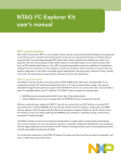


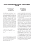

![MC45 User Guide Addendum [English] (P/N MN000113A01 Rev. A)](http://vs1.manualzilla.com/store/data/006176551_1-119e400895b9264a36e3ab3b3a3ca7eb-150x150.png)